
CIVE 450 Notes Course, Fall 2010
American University of Beirut · Water and Wastewater Treatment and Laboratory · 45 pages


Showing the first 10 of 45 pages. Download the PDF to see all of it.
More CIVE 450 files
- Homework Problems · Fall 2015HomeworkView
- Lab Report 1 · Spring 2014LabView
- Midterm · Spring 2014ExamView
- Problems Page 1 · Spring 2014ProblemsView
- Problems Page 2 · Spring 2014ProblemsView
- Problems Page 3 · Spring 2014ProblemsView
- Problems Page 4 · Spring 2014ProblemsView
- Problems Page 5 · Spring 2014ProblemsView
Show the text of this notes
CIVE 450
Water and Wastewater
Treatment
Water Treatment
-
Introduction to water treatment
-
Water treatment processes
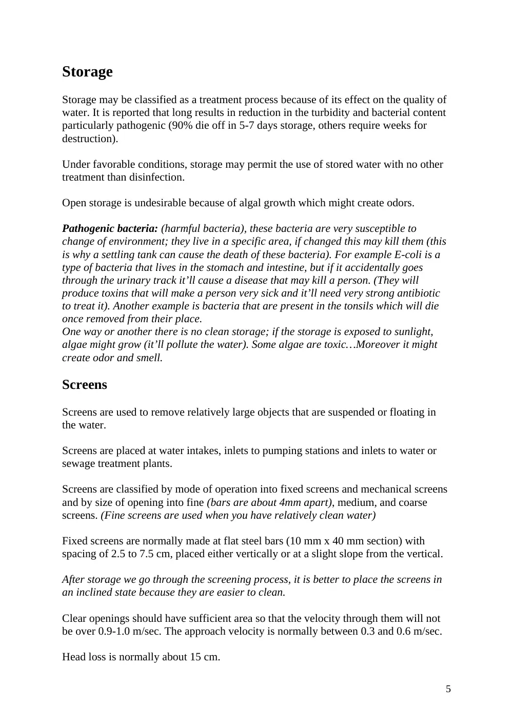
Storage
Screening
Sedimentation
Coagulation/Flocculation
Filtration
Miscellaneous treatment processes
Introduction
The objectives of water ad wastewater treatment lie in the removal of water-laden
impurities in order to render them fit for use, re-use or disposal without inducing
negative impacts on health or the environment.
The type and extent of treatment will depend on the type of impurities present in the
water and the ultimate use of the water.
Condensation of water takes place on a particle of dust, thus water gets polluted as
soon as it is formed. As water comes down (rain), it picks gases, dust, bacteria,
viruses, etc… So by the time water reaches the ground it is polluted. As water moves
on the ground it picks up more and more pollutants (mostly suspended solids and this
is why water in a river is not clear). When water on the other hand seeps into the
ground, suspended solids are filtered and minerals are induced in the water (this is
why groundwater is crystal clear)…
…So the difference between surface water and ground water is that ground water is
filtered out… suspended particle are removed but minerals are induced.
Normally (in conventional water treatment) we do not remove minerals from water
(we mostly remove particles that we can see), unless water is needed for a specific
purpose… So in other words we can say that we undertake specific treatment for
specific objective/purpose or ultimate use of the water.
In both cases (whether we have ground or surface water), even if the water is crystal
clear we always disinfect the water from bacteria. (Remember that we treat the water
according to its ultimate use; so even if we dispose of that water we should make sure
that it doesn’t harm the environment).
Ultimate use: what we will use the water for.
1
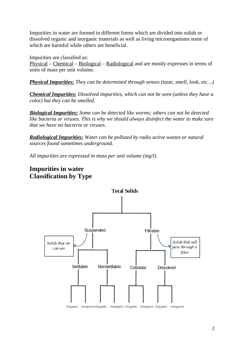
Impurities in water are formed in different forms which are divided into solids or
dissolved organic and inorganic materials as well as living microorganisms some of
which are harmful while others are beneficial.
Impurities are classified as:
Physical – Chemical – Biological – Radiological and are mostly expresses in terms of
units of mass per unit volume.
Physical Impurities: They can be determined through senses (taste, smell, look, etc…)
Chemical Impurities: Dissolved impurities, which can not be seen (unless they have a
color) but they can be smelled.
Biological Impurities: Some can be detected like worms; others can not be detected
like bacteria or viruses. This is why we should always disinfect the water to make sure
that we have no bacteria or viruses.
Radiological Impurities: Water can be polluted by radio active wastes or natural
sources found sometimes underground.
All impurities are expressed in mass per unit volume (mg/l).
Impurities in water
Classification by Type
2
Water is referred to as contaminated (polluted) when it contains materials which
render it unsuitable for its intended use.
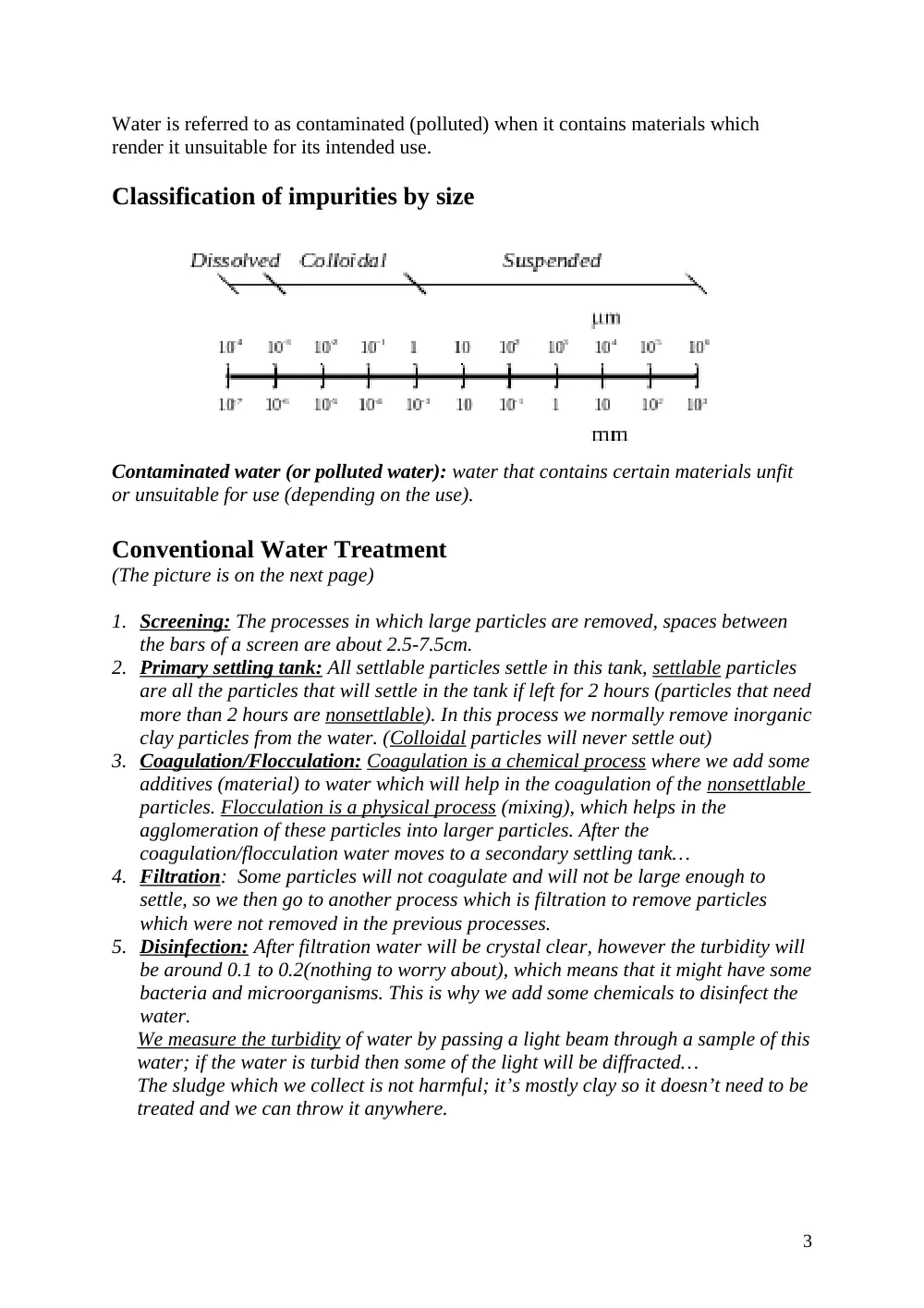
Classification of impurities by size
Contaminated water (or polluted water): water that contains certain materials unfit
or unsuitable for use (depending on the use).
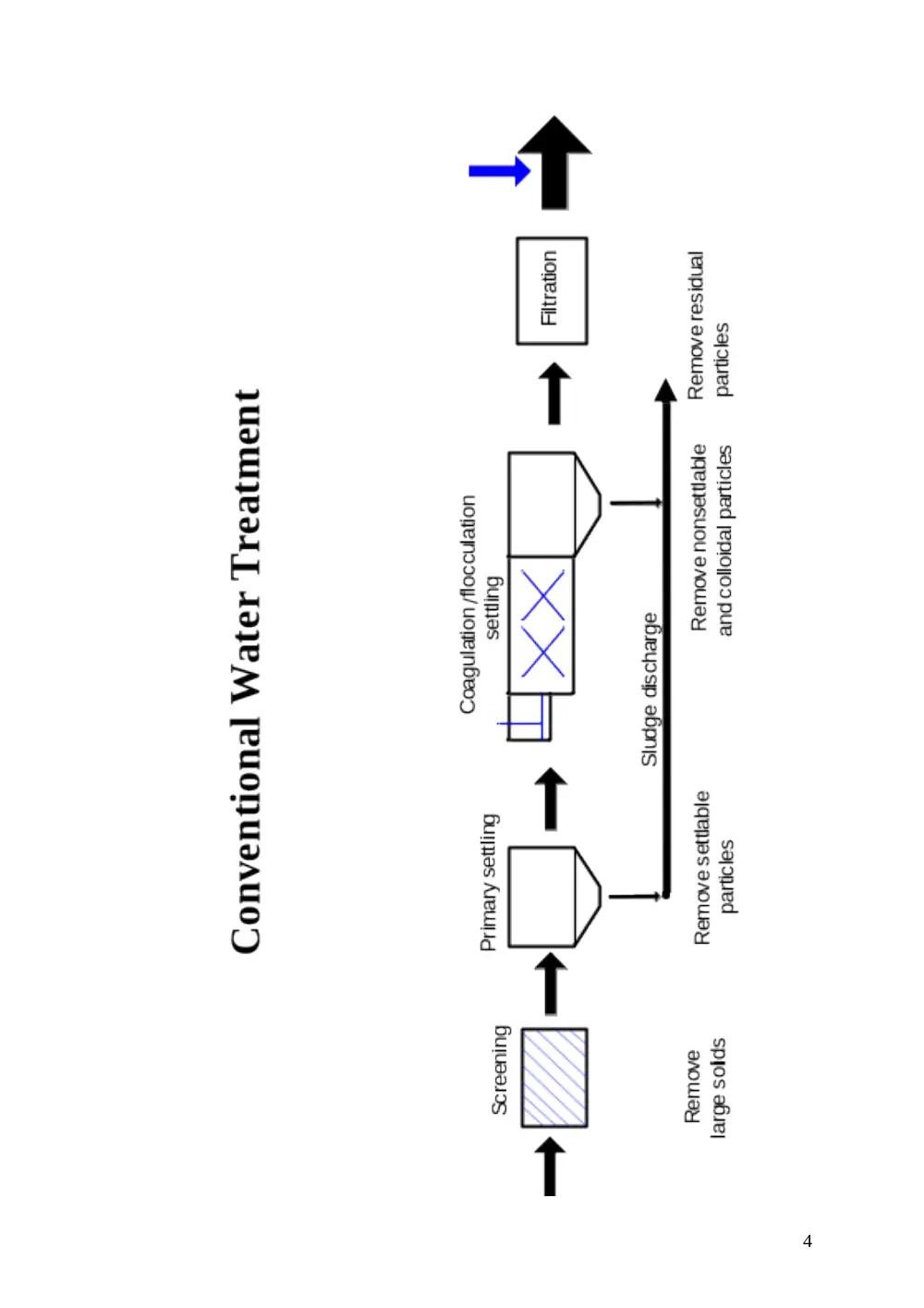
Conventional Water Treatment
(The picture is on the next page)
1. Screening:
The processes in which large particles are removed, spaces between
the bars of a screen are about 2.5-7.5cm.
2. Primary settling tank:
All settlable particles settle in this tank, settlable particles
are all the particles that will settle in the tank if left for 2 hours (particles that need
more than 2 hours are nonsettlable). In this process we normally remove inorganic
clay particles from the water. (Colloidal particles will never settle out)
3. Coagulation/Flocculation:
Coagulation is a chemical process where we add some
additives (material) to water which will help in the coagulation of the nonsettlable
particles. Flocculation is a physical process (mixing), which helps in the
agglomeration of these particles into larger particles. After the
coagulation/flocculation water moves to a secondary settling tank…
4. Filtration
: Some particles will not coagulate and will not be large enough to
settle, so we then go to another process which is filtration to remove particles
which were not removed in the previous processes.
5. Disinfection:
After filtration water will be crystal clear, however the turbidity will
be around 0.1 to 0.2(nothing to worry about), which means that it might have some
bacteria and microorganisms. This is why we add some chemicals to disinfect the
water.
We measure the turbidity of water by passing a light beam through a sample of this
water; if the water is turbid then some of the light will be diffracted…
The sludge which we collect is not harmful; it’s mostly clay so it doesn’t need to be
treated and we can throw it anywhere.
3
4
Storage
Storage may be classified as a treatment process because of its effect on the quality of
water. It is reported that long results in reduction in the turbidity and bacterial content
particularly pathogenic (90% die off in 5-7 days storage, others require weeks for
destruction).
Under favorable conditions, storage may permit the use of stored water with no other
treatment than disinfection.
Open storage is undesirable because of algal growth which might create odors.
Pathogenic bacteria: (harmful bacteria), these bacteria are very susceptible to
change of environment; they live in a specific area, if changed this may kill them (this
is why a settling tank can cause the death of these bacteria). For example E-coli is a
type of bacteria that lives in the stomach and intestine, but if it accidentally goes
through the urinary track it’ll cause a disease that may kill a person. (They will
produce toxins that will make a person very sick and it’ll need very strong antibiotic
to treat it). Another example is bacteria that are present in the tonsils which will die
once removed from their place.
One way or another there is no clean storage; if the storage is exposed to sunlight,
algae might grow (it’ll pollute the water). Some algae are toxic…Moreover it might
create odor and smell.
Screens
Screens are used to remove relatively large objects that are suspended or floating in
the water.
Screens are placed at water intakes, inlets to pumping stations and inlets to water or
sewage treatment plants.
Screens are classified by mode of operation into fixed screens and mechanical screens
and by size of opening into fine (bars are about 4mm apart), medium, and coarse
screens. (Fine screens are used when you have relatively clean water)
Fixed screens are normally made at flat steel bars (10 mm x 40 mm section) with
spacing of 2.5 to 7.5 cm, placed either vertically or at a slight slope from the vertical.
After storage we go through the screening process, it is better to place the screens in
an inclined state because they are easier to clean.
Clear openings should have sufficient area so that the velocity through them will not
be over 0.9-1.0 m/sec. The approach velocity is normally between 0.3 and 0.6 m/sec.
Head loss is normally about 15 cm.
5
Fixed screens: are a group of bars that are placed in a channel and are fixed there.
To clean the screens, we use a fork shaped bar to clean the bars by moving the stuck
material upward.
Movable screens: These screens works as follows… when the mesh rotates, wastes
are taken up to a trough (similar to the one used in the fixed screens), such that it’s
open edge is facing the mesh.
The drop in the level of water after the screen shows that we have a head loss which is
created by the screen (the head loss will increase more if the screen is not clean… if
the head loss is about 15cms then the screens are relatively clean, but if the head loss
reaches 30cms, clean the screens). The velocity of water will prevent any settling, also
at the screen the velocity will be greater than the approach velocity due to the
reduction of the cross sectional area at the bars… (The approach velocity will be
approximately between 0.5 to 0.6 m/s while it’ll be around 0.9m/s at the screens).
6
Sedimentation
(Settling or clarification)
Sedimentation is a physical process used in the separation of solid particles from the
liquid phase.
A particle in still fluid of less density will move vertically downward because of
gravity. It will accelerate until the frictional resistance of the fluid approaches the
impelling force, and thereafter the vertical velocity will remain constant.
Final velocity is known as the settling velocity.
Selltable, suspended, inorganic solids are removed in primary settling. Particles in
the water will only accelerate for few cms of settling… then the particles in the water
will move at a constant velocity (the settling velocity)…
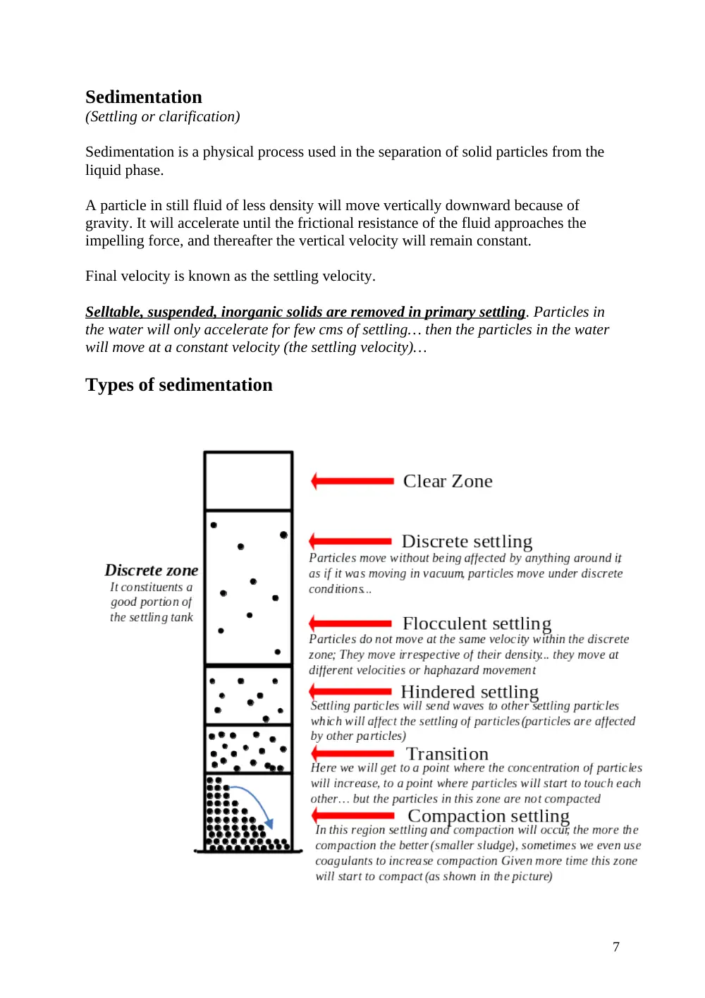
Types of sedimentation
7
Discrete
settling
Refers to the sedimentation of
particles in a suspension of low
solids concentration. Particles
as individual entities with no
interaction
Removes grit and sand
particles
Flocculent
settling
Refers to a rather dilute
suspension of particles that
coalesce or flocculate while
settling. Mass builds up &
settles at a faster rate
Removes a portion of
the suspended solids in
primary settling and in
upper portion of
secondary settling
facilities
Hindered
settling
Refers to suspensions of
intermediate concentration, in
which inter-particle forces are
sufficient to hinder the settling
of neighboring ones
Occurs in secondary
settling used in
conjunction with
biological treatment and
thickening facilities
Compaction
settling
Refers to settling in which the
particles are of such
concentration that a structure is
formed and further settling
occurs only by compression of
the structure
Occurs in the lower
layers of a deep sludge
mass, such as in the
bottom of a deep
secondary settling and in
a sludge facilities
Discrete settling
Net downward force
Drag force
At ultimate settlings (at settling velocity, the impelling force = the drag force)
8
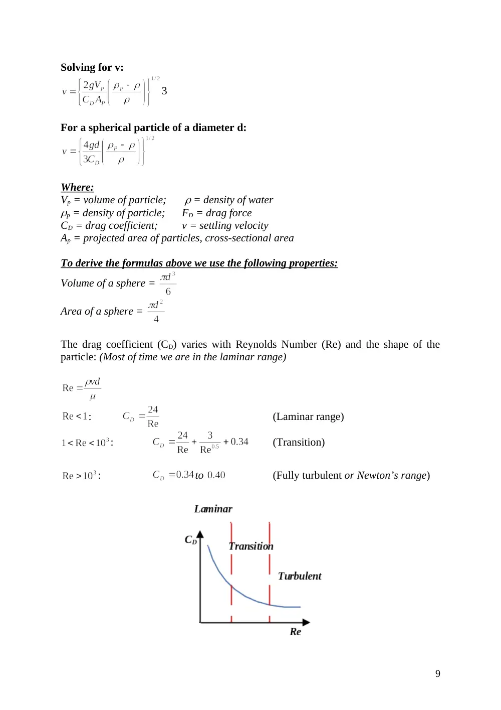
Solving for v:
3
For a spherical particle of a diameter d:
Where:
Vp = volume of particle;
= density of water
p = density of particle;
FD = drag force
CD = drag coefficient;
v = settling velocity
Ap = projected area of particles, cross-sectional area
To derive the formulas above we use the following properties:
Volume of a sphere =
Area of a sphere =
The drag coefficient (CD) varies with Reynolds Number (Re) and the shape of the
particle: (Most of time we are in the laminar range)
:
(Laminar range)
:
(Transition)
:
to
(Fully turbulent or Newton’s range)
9
At discrete settling, the velocity is equal to:
(Laminar or Stoke’s range)
The design of ideal settling basins takes into consideration the removal of all particles
that have a settling velocity greater than a specified settling velocity.
In this case the design is based on discrete particle settling.
While designing a settling tank, we specify what our settling velocity is and we design
the tank such that all particles with this velocity or greater will be removed; also some
particles with smaller velocities will also be removed.
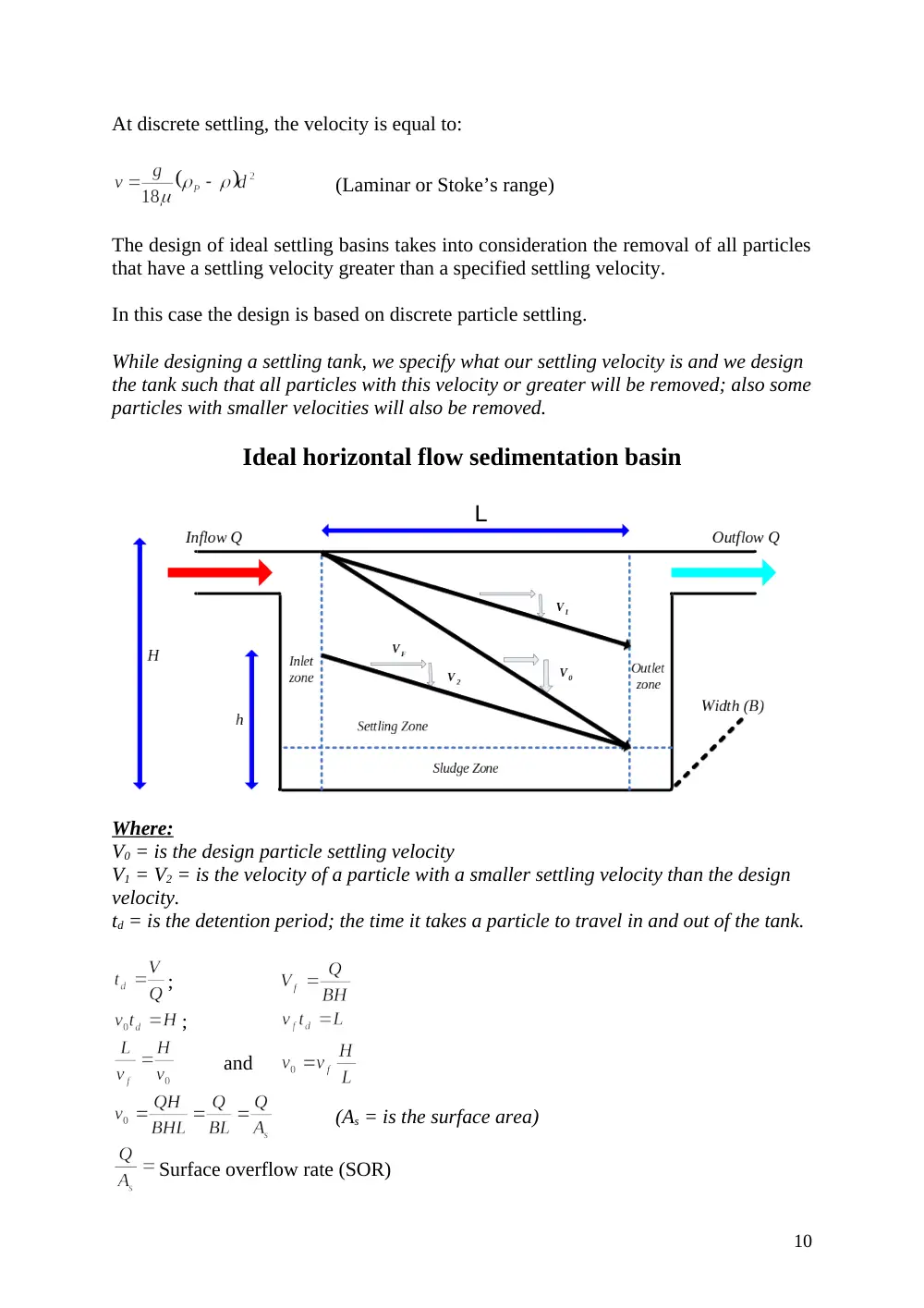
Ideal horizontal flow sedimentation basin
Where:
V0 = is the design particle settling velocity
V1 = V2 = is the velocity of a particle with a smaller settling velocity than the design
velocity.
td = is the detention period; the time it takes a particle to travel in and out of the tank.
;
;
and
(As = is the surface area)
Surface overflow rate (SOR)
10
Short circuiting: when water travels directly out… (Not our case)
SOR = It is used as a design criteria for the design of settling tank. (although SOR
= V0 , we usually talk in terms of SOR in design not velocity)
To improve the settling tank WITHOUT changing its dimension we can try to add
horizontal trays (flat sheets), or inclined trays (Which is better)…
Particle removal in settling tanks
All particles with a settling velocity equal to v0 or more will be removed to the settling
tank while particles with settling velocities less than v0 will be partially removed
depending on their level of entry to the settling tank.
Assuming that a particle with settling velocity v, which is less than v0, will travel a
vertical distance, h, in the time td; then h = vtd
All particles with settling velocity v that enter at a depth h or lower will be removed.
The criterion for removal of particles with this settling velocity is:
The fractional removal of particles with this settling velocity is:
To determine the efficiency of a settling tank, i.e. the percent removal of suspended
solids for discrete and flocculent settling, two methods are normally adopted. The first
is the Particle Size Distribution method and the second is the Settling Column
Analysis method.
The first is performed by establishing a settling velocity cumulative frequency curve.
This is performed by classifying the percent weight fraction greater than the stated
size for particles of different sizes, then determining the settling velocities and Re of
each weight fraction. The curve is then drawn using the generated data, fraction with
settling velocity less than stated v/s terminal settling velocity.
Efficiency of treatment =
(Particle size Method)
CI = Concentration Influent
CE = Concentration Effluent
11
The previous method can only be used if all particles have the same density; this is
why we can not apply this method to flocculent particles. More will be discussed later.
The overall removal may thus be calculated using the following formula:
(vs is the settling velocity, &
)
The Settling Column Analysis is conducted by performing a settling test using a
column from which samples are withdrawn at regular time intervals from multiple
ports along the column and analyzed to determine the reduction is suspended solids.
Note: In the above formula take vs as the average between two velocities… This
method will not work with flocculent particles, since flocculent particles change their
densities and velocities as they move downward (settle). So for flocculent particles we
use the settling column analysis (take a sample and follow up, as shown below)…
12
- Mix water to get even distribution of particles.
- At t = 0, take a sample and measure the turbidity and record
- At t = t1, take samples from each opening; measure the turbidity and record…
- The samples taken up will have less particles than down…
- Then repeat the work in the 10-20 minutes for about 2 hours.
- You can change (increase) intervals of time, because settling will slow with time.
- After measuring the percent removal (efficiency) at different depth we plot a graph
and get the following:
13
Percent removals are then plotted as numerical values versus depth and time as shown
in figure. (as shown below, we join points having equal efficiencies)
From this plot the removal obtained at various times may be predicted and a
theoretical SOR can be established.
The efficiency may be calculated using the following relationship:
For example to find the efficiency at 20 minutes we draw a vertical line at t = 20
minutes and we use the above formula… so we’ll get:
After we find the percent efficiency of removal for a certain time, we multiply this time
by a factor of safety of 1.5. So for example if we get 70% removal for a time of 40
minutes, then we use (practically) a time of 1.5 40 = 60 minutes…
We use the above method for flocculent particles since velocity & density of particles
change while particles are settling, since these particles get heavier & heavier and
thus gaining speed as they move down…
14
Hindered Settling
The governing principle for design of settling tanks is vs < Q/As and the limiting
settling velocity of the suspension will be the design settling velocity vs.
The rate of settling in the hindered settling region is a function of the concentration of
solids and their characteristics.
Settling tests are usually required to determine the settling characteristics of
suspension where hindered and compression settling are important consideration. The
settling column analysis is normally used to obtain the needed data.
Special tanks are used as secondary tanks to make water thicker and these are called
thickening tanks. In these tanks hindered settling occurs at the beginning of the tank
since we’ll have a lot of particles after the Coagulation/flocculation process and
particles will thus affect each other, causing hindered settling…
Interface: Is the line between the liquid and solid phase (considering that all particles
move at the same time)
The line (or interface) is receiving particles from up, therefore it is increasing in size.
However at the same time it is compacting. So the net movement (up/down) of this line
is the difference between the filling and compaction (or settling) at the interface.
Assuming that these two are equal, we can say that the movement of the interface line
in the zone above 1 (hindered zone) is faster than it is between 1 & 2 (transition zone)
and faster than below 2 (compaction zone). In other words we can say that as the
interface line moves downward it somehow decelerates… more concerning this is
illustrated in the graph next page.
15
The area requirement for thickening is determined by measuring the rate of subsidence
of the interface in the settling column test and drawing a graph. The final overflow
rate selected should be based on a consideration of the following factors:
The area needed for clarification (Discrete settling)
The area needed for thickening (Hindered settling)
The rate of sludge withdrawal (Consider in practical approach)
Because the area required for thickening is usually greater than the area required for
settling, the rate of free settling rarely is the controlling factor.
As I explained before the rate of movement of the interface in the hindered zone (steep
slope) is faster than it is in the transition (curve) & compression zone (mild slope)…
We design the tank for either hindered or compacting settling. If we are interested in
designing for hindered settling, we can take the slope of the hindered phase as the
rate of settling to determine a detention period for a certain concentration. If we’re
interested in the compaction settling we use the slope of the compression settling
phase…
To determine a good estimate of the detention period we proceed as follows:
1. Extent the hindered and compression curves till they meet.
2. Find these two lines’ bisector and extend it to the curve.
3. Draw the tangent of this curve at the point of intersection
4. Knowing C0, H0, and Cu find Hu such that C0H0 = CuHu.
5. Using the tangent (which we drew) and knowing the value of Hu, get tu.
After we get tu, the underflow detention time we can now get the surface area…
16
The rate at which the interface subsides is equal to the slope of the curve at that point
in time.
The area required for thickening is given by the following equation:
The critical concentration controlling solids handling capability of the tank occurs at
height H2 where the concentration is C2.
Scour
The horizontal velocity in a settling tank should not exceed the scour velocity or else
the settled particles will be re-suspended.
The scour velocity is given by:
Where: v = horizontal velocity of flow
S = Specific gravity of the particle
d = diameter of particle
= a dimensionless constant ranging from 0.04 to 0.06
f = dimensionless Darcy-Weisback friction factor usually 0.02 to 0.03
In determining the size of a settling tank, three design criteria have to be satisfied,
namely, surface overflow rate (SOR), detention period, weir overflow rate
(WOR). Based on the type of settling tank being designed, a specific SOR range, a
detention period range and an WOR range are specified. Based on these values the
size and dimensions of the tank are determined using the following steps.
1. Determine the volume of the tank
V = Qt, where V is the volume, Q is the flow, and t is the detention period.
2. Knowing the volume and the SOR, the surface area of the tank may be
determined from the following:
SOR = Q/A
3. Having the volume and the area, the depth of the tank is determined;
d = V/A; d normally ranges between 3 and a maximum of 6 m.
In designing a settling tank we consider three criteria (as stated above) which are:
1. SOR
2. WOR
3. Theoretical detention period
17
3. The theoretical detention period is different from the actual detention period
because of some environmental factors. These include wind that can impact
the movement of the water horizontally, or water having different
density/temperature which will results in currents that will cause the water to
stay for less time…This is why design criteria of a tank is based on experience.
2. The water overflow rate (WOR) is rate at which water goes over the weir. If
WOR is too high will result in turbulence in the tank which can pick up
particles… So we should control the flow over the weir such that to have no
turbulence…
Units: WOR is expressed in m3/m/ unit time or m2/s, while the SOR is expressed
in m3/m2/ unit time or in m/s. The detention period t is expressed in hours and
the flow Q in m3/day (We have to convert the units when we use the formulas).
Dimensions: Usually we prefer to have a depth between 2 – 3.5 meters. Also
the average optimal ratio of the width to the length of the tank is 1:3 to 1:5 (the
width should not be bigger than the length).
Formulas:
If the WOR is larger than the specified range and we don’t want to change the
dimensions of our tank then we can do the following:
1. Increase the length of the weir by zigzagging the weir
2. Add another trough (double weir system)
18
Types of settling tanks
Settling tanks could be either rectangular, circular, square, tube settlers. The most
commonly used are the rectangular and circular tanks.
We have two types of tanks
1. Rectangular (usually used for water treatment; more efficient for small areas)
2. Circular (usually used for wastewater treatment; gives a better distribution of
water in the tank)
Rectangular tank
The inlet structure should be designed to distribute the water as much as possible
in the tank (we have to get a good distribution).
In this settling tank we have two types of wastes which are scum and sludge. Scum
will float and sludge will go down (settle) because the density of scum is less than
that of water, while sludge has a density greater than water so it’ll go down.
Scraper board: made of plastic or wood (rose wood) they are connected to two
chains that enable they’re movement; as it turns it scrapes the sludge down
towards the direction of the hopper.
Skimmer: it is a truncated pipe that collects scum coming from the scraper board.
(this is how we get rid of scum).
Hopper & sludge removal: sludge can be removed by 2 methods, 1 is to insert air
through another pipe which will result in lighter air that will push the sludge
upward… and the other is due in pressure the pipe that will allow the sludge to go
out (I am not sure about this one).
Circular tank (side view)
19
(Top view)
During the settling process we usually use a system consisting of more than one
settling tank in case something goes wrong. For example if we consider the case
where we have two tanks then if one of these is stopped the flow of water will all be
transferred to the other tank, this will reduce the detention time which will result in
less settling (less efficiency of removal)… Moreover the increase in the flow of water
will cause the tank to overflow…
The main problem that will occur due to this is not really related to efficiency, since
most of the particles will be removed at the beginning of the settling process (as
20
shown in the graph). The main problem that will occur is the overflow of the tank
because of the excess flow (the tank received an additional ½Q; the flow doubled).
Now if we increase the number of tanks in our system we will avoid any overflow
problem. If we consider that we have a system of four settling tanks, then in case one
is stopped the other 3 will receive an additional flow of 1/12 Q which will not cause
an overflow.
Design of Trough
(or a launder)
Free board = we allow for an extra 4 – 5 cm of height in the case water overflows…
In the formulas next page the following terms are defined as:
- hC is the critical depth
- q is the overflow per unit length
- A (the surface area) varies with the section of flow, so take the areas of different
sections and take their average…
21
Maximum depth,
Substitute in equation for H,
then
where b = width of the trough
Total depth of trough below weir;
Where s is head loss per unit length;
Free board = 5 cm
Design criteria are given as a function of the type of settling tank:
min
average
max
Detention time (t)
0.2 h
2-4
8
SOR m/d
20
30-50
100
WOR m2/d
175
250
350
Coagulation/Flocculation
Coagulation/flocculation is a treatment process that is used to remove non-settlable
and colloidal particles from water and wastewater.
Coagulation involves the addition and rapid mixing of a part of coagulant resulting in
destabilization of the colloidal and fine suspended solids and the initial aggregation of
the destabilized particles.
Flocculation is a process where slow stirring or gentle agitation is effected resulting in
further aggregation of the destabilized particles and form a rapid settling flock.
The non-settlable particles in water normally have sizes that range from 0.1 micron to
100 microns the bulk of which are colloidal particles. The movement of these particles
in water is very much affected by electrokinetic forces which are a function of the
concentration of surface charges.
22
The surface charge on colloidal particles is the major contributor to their long term
stability. When a solid colloid stays in suspension and does not settle, the system is in
a stable condition.
Particle charge results from preferential adsorption or from ionization of chemical on
the particle surface.
In the previous process we removed settlable particles, and now we are left with
nonsettlable & colloidal particles. In order to remove these particles we have to help
them settle down; they are too small to settle and their movement is controlled by their
surface charge, and since they’re mostly –vely charged they repel each other and
remain stable. So we have to destabilize them to allow them to settle… this is why we
introduce certain chemicals to facilitate the process (undertake
coagulation/flocculation)…
Destabilization: once we neutralize the charge of the particles, then we destabilize
that particle, so they start moving and once they do they become able to aggregate…
Preferential adsorption: the affinity to attract other particles (it’s a source of charged
particles along with ionization)
23
A particle
(which is –vely charged)
is surrounded by two layer of waters, one
fixed and the other moving
. The electro-kinetic force of a particle has a certain
distance where it is effective; this force is function of the –ve charges. In the
coagulation/flocculation we aim to destabilize the particle for it to settle…
The fixed layer
is positively charged and will neutralize part of the –ve charges of
the particle (Eta potential), this layer can rarely result alone in the destabilization
of the particle. The thickness of fixed layer is a function of the concentration of
+ve charges; the thinner the layer the less charges it has…
The diffuse layer (or moving layer),
has +ve and –ve charges and results in the
neutralization of the remaining zeta potential. The zeta potential is what we aim to
neutralize when we add extra +ve charges…
Beyond the point of electro-neutrality the electro-kinetic force of the particle has
no effect on other particles.
When we add coagulants to neutralize the particles in water we should not add too
much, because it will result in more +ve charges that won’t allow settling
(repulsion will occur because the of +ve particles this time, so the best thing to do
is to try to have it neutral). In order to know how much coagulants (or +ve
charges) to add we can perform 2 tests, the first is to measure the potential of
water using a special kind of voltmeter, and the second (more common) is to
perform the jar test.
The Jar test
is performed to make sure that we add an optimal amount of
coagulants to the water. It goes as follows:
1. Take samples from the water we are aiming to clean, place them in 6 jars.
2. Add to each jar different concentration of coagulants and mix.
3. You’ll then get in the different jars, flocks of different sizes and of different
settling rates; these results will help us choose the optimal concentration of
coagulant to use (a healthy flock will give an optimal speed of settling).
24
Coagulation involves the addition of chemicals – either hydrolyzing chemical or
polymers.
Upon addition of coagulants to water, three reactions could occur:
1. Dissolution of the salt (reduces zeta potential by altering the ionic
concentration in the bound layer) (breaking up into ions)
Al2(SO4)3
2Al(H2O)6
+3 + 3SO4
-2
2. Hydrolysis (This where the flocks form; as soon as the ion takes a hydroxide)
Al(H2O)6
+3 + H2O
Al(H2O)5(OH)+2 + H+
Al(H2O)5(OH)+2 + H2O
Al(H2O)4
5(OH)2
+1 + H+
3. Polymerization (Complex molecular structures, products of hydrolysis
combine to form polymers)
Al6(H2O)15
+3
Al7(H2O)17
+4
Dissolution of salt (ionization): breaking up into ions; ions which are +vely
charge attract –vely charged particles…
Hydrolysis: Flocks are formed as soon as ions take a hydroxide…
Polymerization; after hydrolysis we keep the flocks in water… and the more we
leave them there the larger they become… we get polymers which have more
complex molecules of hydroxide and which have a higher valence; the higher
the valence the more particles it will attract and the better the coagulant… So
polymers are very strong coagulants. Also you can have many types of these
polymers, some organic and other inorganic but they are expensive.
As the flocks move down they attract s