
EECE 210 Exam 2, Spring 2016
American University of Beirut · Electric Circuits · 9 pages




More EECE 210 files
- Exam 1 Fall 2018 Quiz 1 · Fall 2018ExamView
- Exam 2 Fall 2018 Quiz 2 · Fall 2018ExamView
- Exam 2 (Quiz 2) Clean Copy · Fall 2018ExamView
- Exam 1 · Spring 2016ExamView
- Exam 2 · Spring 2016ExamView
- Exam 2 With Solution · Fall 2016Exam · with solutionView
- Exam PSpice Quiz · Fall 2016ExamView
- Exam 2 · Spring 2015ExamView
Show the text of this exam
American University of Beirut
Department of Electrical and Computer Engineering
EECE 2I0 - Electric Circuits
Qutz 2
Closed Book - No Programmable Calculators - 90 minutes
April 17,2015
Name: KFY- So Lt/noM
Solve the following problems;
Provide your answers on the attached Scantron card;
This question sheet must be returned with the Scantron card;
There is No penalty;
Mark with a pencil your LAST NAME, your First name Initial (FI) and your Middle name Initial (MI);
Mark your AUB ID Number in the box titled "ID NUMBER";
Write the name of your course instructor on the Scantron card;
Use a pencil for marking your answers ;
When using an eraser, make sure that you have erased well.
This exam has 9 pages.
Course Instructors: L. Hamandi, S. Khaddaj, Y. Nasser, and R. Jabr.
ID:
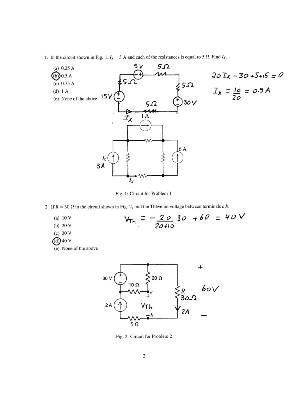
1. In the circuit shown in Fig. 1,15: I A and each of the resistances is equal to 5 0. Findfu.
5V
(a) 0.25 A
@o.sa
(c) 0.75 A
(d) 1A
(e) None of the above I 5 Y
rs
3A
(a) 10V
(b) 20 v
(c) 30 V
@+ov
(e) None of the above
512
30v
2oT7
Jy
-3o *5+6 = O
lo = o,5A
2o
)
-vv\r----_-l
I
I
I
l.,{
c
)
I
6
I
A
TX
Fig. 1: Circuit for Problem 1
2. lf R: 30 O in the circuit shown in Fig.2, flnd the Th6venin voltage between terminals a,b.
\4r.,.= -ffi5, +60 = ?oV
+
R
6oV
3o-Q
2A
5fr
Fig. 2: Circuit for Problem 2
5A-
2t).
T
3. If 1s : 5 A in the circuit shown in Fig. 3, find the Th6venin voltage between terminals a,b.
(fra v
(b) 12 v
(c) 14 V
(d) 16v
2Vx
(e) None of the above
T= 5o-lo = ?A
lo+z+8
Vx = 2Z= 4V
lt
Vrp, - -?Vx +/o+ 8J
--2(4)+tD+g(2)
: 18 V
15
5A
Fig. 3: Circuit of Problem 3
In the circuit shown in Fig. 4, Ra:3 O. Find the value of Rz, that results in maximum power being
transferred to R1.
(@', n
(b) 16 O
(c) 17 A
(d) 18 O
(e) None of the above
6r}
Fig. 4: Circuit of Problem 4
Kt=&n= to+3+3116
= lS +Z
= (5{L
10a
5. If V5 : 120 V in the circuit shown in Fig. 5, find the maximum power that can be delivered to R2.
(a) 329.t4w
(b) 302.29w
(c) 228.57 W
@eo.rr*
(e) None of the above
VS
vrn = 4o (p")
( 8x2o + 40) = -lott V
4o+lo
- ?8{2
= q6,5+ w
10 g)
-vltv1d----!
MI
wi
FI +*c)
ffi
YYVY
M *u @
40v
t?ov
Fig. 5: Circuit of Problem 5
6. In the circuit shown in Fig. 6,V7:120 V. Find the component of 15 resulting from the yr voltage
source acting alone, with all the other voltage and current sources deactivated.
(a) 1A
(b) 2A
(c) 3A
@oo
(e) None of the above
l2o
5tro +/5
= tlA
Fig. 6: Circuit of Problem 6
Tl
Jg
7. In the circuit shown in Fig. 7, Vcc:2.5 V. Find the maximum value of Rx that can be used such that
the op-amp operates in its linear region.
(a)r5Q
o'al+ $u
6fuoo
.u-
(c)45o
l+ 2Vr1 +\
(d) 60 o
(e) Noneof theabove VD = 3 Vn + I
Vn-Vo = c2
'tM
V, =o
4,5 =) Vn - o.5
o., Fx + tS
-- Rx r,)
By+3 o
=Ex
€4 = 3oc2
.+
T,
Fig. 7: Circuit of Problem 7
Each op-amp shown in Fig. 8 is operating in the linear region, and each of the resistances is equal to
10 O. If ys : 6 V and Vr :24 V, find the current 16r.
(a) 0.5 A
@o.oo
(c) 0.7 A
(d) 0.8 A
(e) None of the above
l3r.+6 +Z+
lo
3oIo = 18
I:,I--ZU = O
/o
-)
= o'64
Fig. 8: Circuit of Problem 8
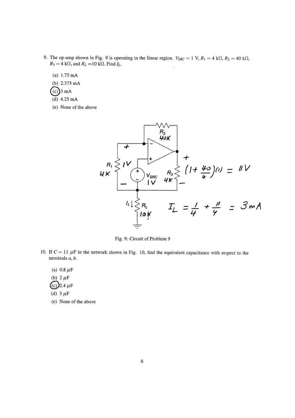
9. The op-amp shown in Fig. 9 is operating in the linear region.
R: : 4 kO, and Rr :10 kO. Find [.
(a) 1.75 mA
(b) 2.375 mA
@''"o
(d) 4.25 mA
(e) None of the above
R1
UK
Vsnc:1 Y Rr :4 kf), Rz :40 kO,
+
(t+ ?yu = ttv
: 3-A
I --ll
q?
Fig. 9: Circuit of Problem 9
10. If C: ll ruF in the network shown in Fig. 10, find the equivalent capacitance with respect to the
termir,als q, b.
(a) 0.8 triF
(b) 2 ttF
@zl pr
(d) 3 pF
(e) None of the above
+
tv
Iv ,ft
lt*t = 6f F
2
C"b
!*t
6 3+z
4l,-il
2o
=) Cro = 2'47f
Fig. l0: Circuit of Problem 10
11. In the circuit shown in Fig. ll, L1 :4H, lrz- 4H, and M:2H. Write the mesh-current equation
around mesh 2 (corresponding to mesh-current i2).
(a) 6(d\ I dt) - t3(di2l dt) - t4i2 : Q
((b))6(di I ldt\ - t2(dizldt) - t4i2: Q
\-7
(c) 6(di1 I dt) - tl(di2l dt) - t4i2 : s
(d) 6(dit I dt) - t}(diz/ dt) - t4i, : o
(e) None of the above
4H
L2 Bn
4n
4 oluz
'-+
d+
-6d[,
dt
zd-(ir-t,)
+ /Z di, + ltt
dt
Fig. 1 1: Circuit of Problem 1 I
+ tqt:z + 4d (tz-\)
4t
+ 2 olt',
E
=o
iz -0
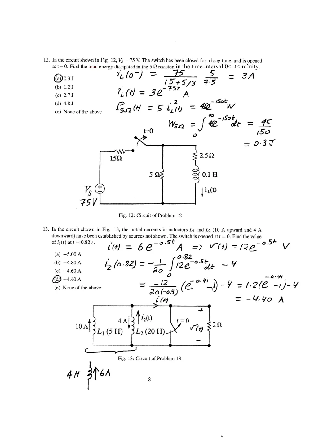
12. In the circuit shown in Fig. l2,Vs:75 V. The switch has been closed for a long time, and is opened
at t = 0. Find the total energy dissipated in the 5 f,) resistor.
@0, r
?Lb-) -- 7;
(b) t.z.r
I 5+ f B
(c) 2.7,
?tft) = 3 e- 75t '
(d) 4.8 J
(e) None or rhe above 'Prn f4 = S irlO =
7-5
3A
4e
,t5,
= O'3{
-tbt
1&- W
Jb-',*b,
2.5 r}
VS
75v
Fig. 12: Circuitof Problem 12
13. In the circuit shown in Fig. 13, the initial currents in inductors L1 and Lz 00 A upward and 4 A
downward) have been established by sources not shown. The switch is opened at t : O. Find the value
oti2(t)atl:0.82s. l(fJ -_ 6 e-o.St
^
=) tr1) = /?€_ o.St V
(a) -5.00 A
(b) -4.80 A
(c) -a.60 A
@ -+.+o e,
(e) None of the above
Wsn =
t={
0.1 fi
lir"(O
I
ir(,.s2) = -* If;T-".,fu - q
o
= _tz /;o.0,-^l_/ =
eo.Go.S) r"
t(4
=
_o.vt
t.? @ -,)- ,/
- 4, tlo A
zil
4^l
tr(5H) I f r'tt)
I"2 (20 H)
firt
4 n ir'^
Fig. 13: Circuit of Problem 13
in the time interval 0<=t<infinity.
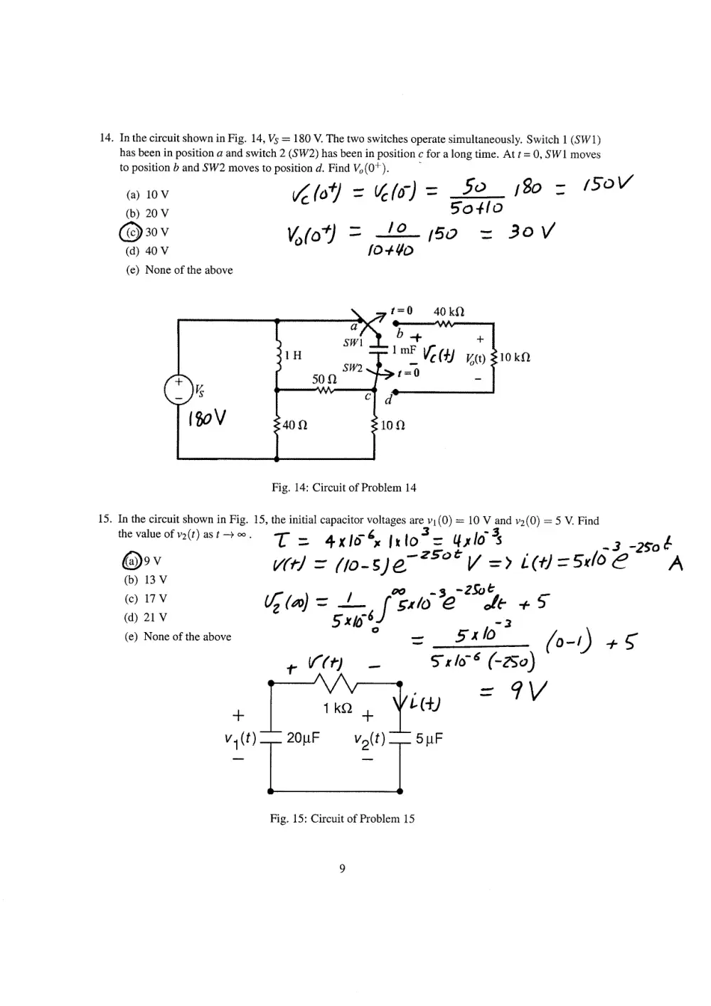
14. In the circuit shown in Fig. 14, Vs : 180 V. The two switches operate simultaneously. Switch I (SW1)
has been in position a and switch 2 (SW2) has been in position c for a long time. At / = 0, SWI moves
to position b ard SW2 moves to position d. Find %(0+).
=50
tgo = tioV
(a) 10V
(b) 20 v
(t}ro,
(d) 40 v
(e) None of the above
6,b1 = /r(t)
Vobl =,#
5ollo
tso = 3ov
b+
lmF
r *:o
srr/l
SW1,
40 ko
frtU
r0 kfi
I
v"(r)
15.
Fig. 14; Circuitof Problem 14
In the circuit shown in Fig. 15, the initial capacitor voltages are u1(0) : 10 V and u2(0) :5 V. Find
thevalueorv2(t)as/-+€. T = 4xlt6, ltlot_= ltto3s
._3 _2rof
@rt
/(r/ = (to-s)g-z,o' V => i(t) =5r/o e -'- A
(b) 13 v
(c) r7v
6t^1 = t f*srti'e-'*1* + i
(d)2rv
5x65J
.-3
(e)Noneofrheabove
o
=
5l=lor- , (O-,) +E
r tf(q
S r ttr' (-su)
I
fr
=qv
, I
1kCI Vtt+l
' __l_
f l_
v,(t)
-
z0pF
vr(t) -
spf
Fig. 15: Circuit of Problem 15