
EECE 210 Exam 2 With Solution, Fall 2016
American University of Beirut · Electric Circuits · 4 pages · Prof. Nassir Sabah · with solution


More EECE 210 files
Show the text of this exam
EECE 210 Electric Circuits
Quiz 2 – Oct 22, 2016
20%
1.
Determine: (a) VO (6 grades), (b) the short circuit current
Iab (6 grades), (c) Thevenin’s resistance seen by a test
current source applied between terminals ‘ab’ (8
grades). Assume R = 10 .
Solution: (a) The current through R is 0.5 – 0.1VO. From
KVL, (0.5 – 0.1VO)R + 20 = VO. It follows that .
(b) When terminals ‘ab’ are short circuited,
VO = 0, and the dependent source
is zero, that is replaced by an open
circuit. It follows that ISC = .
(c) When a test current source is
applied, with the independent
sources set to zero, it follows that ,
so that . Alternatively, the
dependent source is equivalent to a resistance of VT/(0.1VT) = 10 , so that
RTh = 10||R = .
Version 1:
R = 10 , (a) V, (b) ISC = 2.5 A, (c) .
Version 2:
R = 15 , (a) V, (b) ISC = A, (c) .
Version 3:
R = 20 , (a) V, (b) ISC = A, (c) .
Version 4:
R = 30 , (a) V, (b) ISC =
A, (c) .
Version 5:
R = 40 , (a) V, (b) ISC = A, (c) .
20%
2.
Determine IO using NEC, assuming R = 1 (15
grades for NEC, 5 grades for IO).
Solution: On open circuit, it follows from KVL around
the 3 resistor and 3 V source that VTh – 3 –
3 = 0, so that VTh = 6 V.
On short circuit, IN = 2 A, so that RTh = 3 .
Alternatively, if the independent sources are
set to zero, the 6 resistor is short circuited, so that the resistance seen by R is
3 .
Version 1 - p1/4
+
–
a
b
20 V
+
–
VO
R
0.1VO
0.5 A
a
b
+
–
VT
R
0.1VT
IT
R
+
–
20 V
+
–
3 V
3
6
1 A
IO
+
–
20 V
+
–
3 V
3
6
1 A
IN
1 A
+
–
20 V
+
–
3 V
3
6
1 A
+
–
VTh
+
–
3 V
NEC seen by R is as shown. It follows from current division that:
.
Version 1:
R = 1 , A
Version 2:
R = 2 , A
Version 3:
R = 3 , A
Version 4:
R = 5 , A
Version 5:
R = 6 , A.
20%
3.
Determine IS using superposition, assuming R =
5 .
Solution: The dependent source is replaced by an
independent source VY = 5VX. If the 1.5
A source is applied alone, with the
voltage sources set to zero, VX1 =
(80||20)×1.5 = 16×1.5 = 24 V. If the 10 V
source is applied alone, with the other
sources set to zero, no current flows in
the 20 and 80 resistors, so that VX2 =
10 V. If the source VY is applied alone, it
follows from voltage division that VX3 =
. Substituting VY = 5VX, the superposition
equation is: VX = 24 + 10 – VX, or VX = 17 V. From KVL in lower mesh on the
LHS, , and .
Version 1:
R = 5 , = 16.5 A.
Version 2:
R = 10 , = 9 A.
Version 3:
R = 15 , = 6.5 A.
Version 4:
R = 20 , 5.25 A.
Version 5:
R = 25 , = 4.5 A.
2 A
IO
3
R
+
–
10 V
80
20
1.5 A
R
–
+
IS
5VX
+
–
VX
+
–
10 V
80
20
1.5 A
R
IS
VY
+
–
VX
I1
+
–
20%
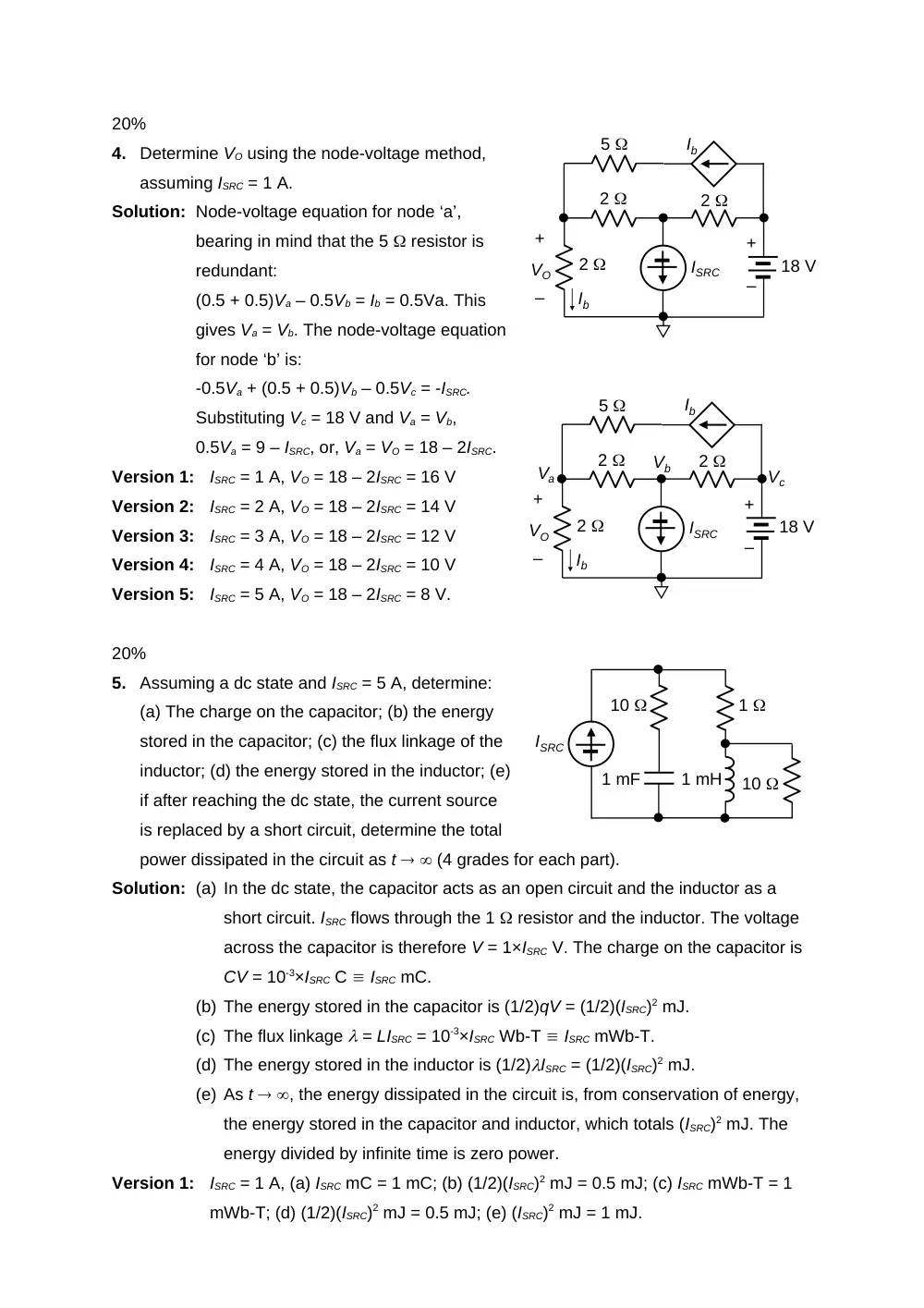
4.
Determine VO using the node-voltage method,
assuming ISRC = 1 A.
Solution: Node-voltage equation for node ‘a’,
bearing in mind that the 5 resistor is
redundant:
(0.5 + 0.5)Va – 0.5Vb = Ib = 0.5Va. This
gives Va = Vb. The node-voltage equation
for node ‘b’ is:
-0.5Va + (0.5 + 0.5)Vb – 0.5Vc = -ISRC.
Substituting Vc = 18 V and Va = Vb,
0.5Va = 9 – ISRC, or, Va = VO = 18 – 2ISRC.
Version 1:
ISRC = 1 A, VO = 18 – 2ISRC = 16 V
Version 2:
ISRC = 2 A, VO = 18 – 2ISRC = 14 V
Version 3:
ISRC = 3 A, VO = 18 – 2ISRC = 12 V
Version 4:
ISRC = 4 A, VO = 18 – 2ISRC = 10 V
Version 5:
ISRC = 5 A, VO = 18 – 2ISRC = 8 V.
20%
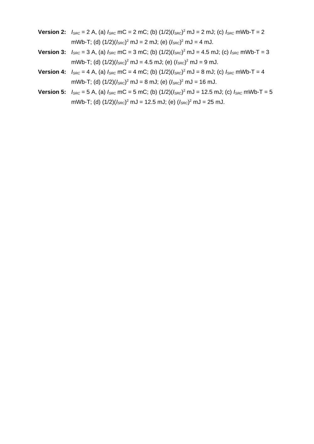
5.
Assuming a dc state and ISRC = 5 A, determine:
(a) The charge on the capacitor; (b) the energy
stored in the capacitor; (c) the flux linkage of the
inductor; (d) the energy stored in the inductor; (e)
if after reaching the dc state, the current source
is replaced by a short circuit, determine the total
power dissipated in the circuit as t (4 grades for each part).
Solution: (a) In the dc state, the capacitor acts as an open circuit and the inductor as a
short circuit. ISRC flows through the 1 resistor and the inductor. The voltage
across the capacitor is therefore V = 1×ISRC V. The charge on the capacitor is
CV = 10-3×ISRC C ISRC mC.
(b) The energy stored in the capacitor is (1/2)qV = (1/2)(ISRC)2 mJ.
(c) The flux linkage = LISRC = 10-3×ISRC Wb-T ISRC mWb-T.
(d) The energy stored in the inductor is (1/2)ISRC = (1/2)(ISRC)2 mJ.
(e) As t , the energy dissipated in the circuit is, from conservation of energy,
the energy stored in the capacitor and inductor, which totals (ISRC)2 mJ. The
energy divided by infinite time is zero power.
Version 1:
ISRC = 1 A, (a) ISRC mC = 1 mC; (b) (1/2)(ISRC)2 mJ = 0.5 mJ; (c) ISRC mWb-T = 1
mWb-T; (d) (1/2)(ISRC)2 mJ = 0.5 mJ; (e) (ISRC)2 mJ = 1 mJ.
+
–
Ib
Ib
+
–
VO
18 V
ISRC
2
2
2
5
+
–
Ib
Ib
+
–
VO
18 V
ISRC
2
2
2
5
Va
Vb
Vc
ISRC
1 mF
1 mH
1
10
10
Version 2:
ISRC = 2 A, (a) ISRC mC = 2 mC; (b) (1/2)(ISRC)2 mJ = 2 mJ; (c) ISRC mWb-T = 2
mWb-T; (d) (1/2)(ISRC)2 mJ = 2 mJ; (e) (ISRC)2 mJ = 4 mJ.
Version 3:
ISRC = 3 A, (a) ISRC mC = 3 mC; (b) (1/2)(ISRC)2 mJ = 4.5 mJ; (c) ISRC mWb-T = 3
mWb-T; (d) (1/2)(ISRC)2 mJ = 4.5 mJ; (e) (ISRC)2 mJ = 9 mJ.
Version 4:
ISRC = 4 A, (a) ISRC mC = 4 mC; (b) (1/2)(ISRC)2 mJ = 8 mJ; (c) ISRC mWb-T = 4
mWb-T; (d) (1/2)(ISRC)2 mJ = 8 mJ; (e) (ISRC)2 mJ = 16 mJ.
Version 5:
ISRC = 5 A, (a) ISRC mC = 5 mC; (b) (1/2)(ISRC)2 mJ = 12.5 mJ; (c) ISRC mWb-T = 5
mWb-T; (d) (1/2)(ISRC)2 mJ = 12.5 mJ; (e) (ISRC)2 mJ = 25 mJ.