
EECE 210 Problems Exam-Solution, Spring 2013
American University of Beirut · Electric Circuits · 41 pages · with solution




Showing the first 10 of 41 pages. Download the PDF to see all of it.
More EECE 210 files
- Exam 1 Questions and Answers · Fall 2015Problems · with solutionView
- Exam Questions and Answers · Fall 2015Problems · with solutionView
- Exam 2 Answer and Questions · Fall 2015Problems · with solutionView
- Problems After Quiz 3 · Summer 2013ProblemsView
- Problems For Quiz 2 · Fall 2012ProblemsView
- Problems For Quiz 3 · Fall 2012ProblemsView
- Problems For Quiz 1 · Fall 2012ProblemsView
- Problems For Quiz 1 · Spring 2012ProblemsView
Show the text of this problems
54.81 kW
120 V, 20 A
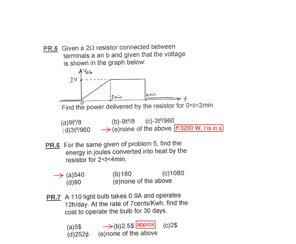
t2/3200 W, t is in s
approx
Hint: redraw as a
bridge circuit
Hint: transform current
sources to voltage sources
VA = 12 V, VB = 10 V,
VC = 22 V
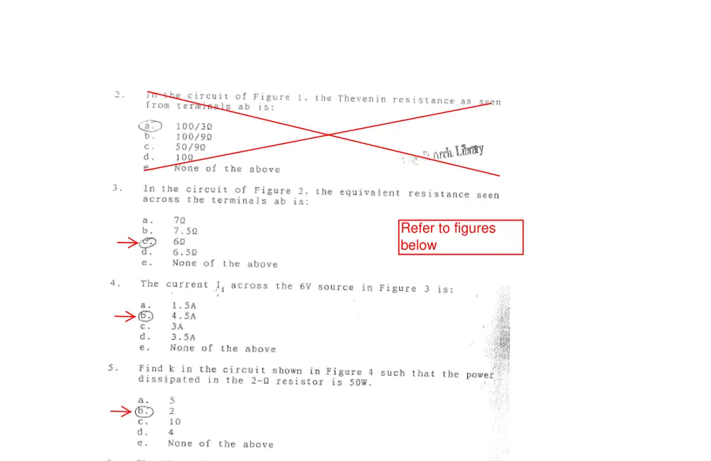
Refer to figures
below
A
50 V
8%
2. Determine Ix in the circuit shown.
+
2 Ω
–
+
–
Is = 5Ix A
2Is V
Ix
4 V
2 Ω
A. 2 A
B. 4 A
C. -2 A
D. -4 A
E. None of the above
Solution: KCL at the upper node gives a
current of 4Ix in the 2 Ω resistor; 2Is = 10Ix;
from KVL around the right mesh: 10Ix = 8Ix
+ 4, so that Ix = 2 A.
+
2 Ω
–
+
–
Is = 5Ix A
2Is V
Ix
4 V
2 Ω
4 Ix
Problem 1
Find Rab.
A) 12 ohms
B) 7.5 ohms
C) 10 ohms
D) 15 ohms
E) None of the above
Problem 2
Find the power
consumed by the 50
ohm resistor in the
circuit shown below
A) P= 0.246 W
B) P= 0.692 W
C) P= 2.358 W
D) P= 5.100 W
E) None of the
above
Problem 3
Find V0 in the 30 Ohm resistor in the circuit
shown below
A) V0 = 6 V
B) V0 = 66 V
C) V0 = 72 V
D) V0 = 78 V
E) None of the above
1
Problem 4
In the circuit shown, find the voltage denoted by Vs1
A) 300 V
B) 150 V
C) -150 V
D) 75 V
E) None of the above
Problem 5
In the circuit shown above, find the value of the load resistance RL in terms of R such
that Vo is 50 V.
A) R/3
B) 3R
C) R
D) 2R
E) None of the above
2
1. The current in a 1 μF capacitor is shown in
the figure as a function of time. The total
energy stored in μJ is:
i
10 mA
t
1 ms
4 ms
A. 40
B. 100
C. 200
D. 50
E. 25
Solution: q at 4 ms is
20
2
4
10
=
×
μC. The energy in μJ is W =
C
C
200
2
(20)
2
=
, where C is
in μF.
2. If VSRC = 10 V, determine Rx so that Ix = 0.
–
+
VSRC
5 Ω
–
+
5 V
Rx
Ix
A. 5 Ω
B. 1.25 Ω
C. 2.5 Ω
D. 1 Ω
E. 1.67 Ω
Solution: When Ix = 0,
5
5
=
+
SRC
x
x
V
R
R
, or
SRC − 5
x
V
25
=
R
Ω.
3. If R
etermine the ratio ρ /α so that I1 = I2.
Ω
E. 8 Ω
Solution:
= 10 Ω, d
A. 4 Ω
B. 10 Ω
C. 6 Ω
D. 5
R
I
I
2
1
6
− ρ
=
,
R
RI
I
1
2
6
−α
=
, or
R
RI
R
I
1
1
6
6
α
ρ
−
=
−
, which gives ρ /α = R.
–
+
–
+
ρ
α
–
+
V1
+
6 V
R
R
I2
V1
–
I2
I1
1/5
4. In the figure shown, the 24 V source having a
source resistance of 1 Ω is replaced by the
equivalent current source, the load resistance RL
being the same. If RL = 5 Ω, the ratio of the
power delivered by the ideal current source to
the power delivered by the ideal 24 V source is:
24 V
–
+
1 Ω
RL
A. 5
B. 11
C. 7
D. 14
E. 9
Solution: The power delivered by the ideal voltage source is
1
24
24
+
×
RL
. The equivalent
current source is an ideal current source of 24 A in parallel with 1 Ω. The power
delivered by the current source is
1
1
24
24
+
×
×
L
L
R
R
. The ratio of the powers is
numerically equal to RL.
– +
3VO V
_
+
VO
2 A
4 A
2 Ω
2 Ω
4 Ω
4 Ω
R
5. Determine VO in the circuit shown if R = 1 Ω
A. 18 V
B. 12 V
C. 30 V
D. 6 V
E. 24 V
Solution: The current through R is 6 A, so that
VO = 6R.
–
+
–
+
–
+
–
+
–
+
a
b
IX
0.5IX V
0.8Vab A
20 V
10 A
6. Given the source connections shown.
Determine the actual power delivered or
absorbed by each source.
Solution: IX = 0.8×20 = 16 A. Current in 20 V
source is 6 A in the direction of a voltage
rise. Voltage across dependent voltage
source is 0.5×16 = 8 V. Voltage across
2/5
dependent current source is 20 – 8 = 12 V. It follows that:
Power delivered by 20 V source is 20×6 = 120 W
Power delivered by 10 A source is 20×10 = 200 W
Power absorbed by dependent current source is 12×16 = 192 W
Power absorbed by dependent voltage source is 8×16 = 128 W
VSRC
–
+
ISRC
+
_
4 V
1.5 A
12 Ω
6 Ω
22 Ω
8 Ω
7. Determine VSRC, ISRC, and the
voltages across the four
resistors in the circuit shown.
(Four grade points for each
answer plus 1 bonus grade).
Solution: Going CCW around the
upper mesh:
VSRC
–
+
ISRC
+
_
4 V
1.5 A
12 Ω
8 Ω
6 Ω
22 Ω
I1
I2
I1+1.5
I2 -1.5
x
4 +12I1 – 8I2 = 0
Going CW around the
lower mesh:
4 – 6(I1 + 1.5) + 22(I2 –
1.5) = 0
The two equations
reduce to:
3I1 – 2I2 = -1
-3I1 + 11I2 = 19
This gives: I1 = 1 A; I2 = 2 A. Hence,
Voltage across 12 Ω resistor: 12 V
Voltage across 6 Ω resistor: 15 V
Voltage across 8 Ω resistor: 16 V
Voltage across 22 Ω resistor: 11 V
VSRC = 27 V
ISRC = 3 A.
3/5
1. Determine the power dissipated in the
circuit, assuming I = 1 A.
I
1 Ω
1 Ω
1 Ω
1 Ω
1 Ω
3 Ω
3 Ω
2 Ω
2 Ω
0.5 Ω
Solution: The 1 Ω Y is paralleled with a 3 Ω Δ,
so that it effectively becomes a 0.5 Ω Y, and the
circuit reduces to that shown. The resistance
seen by the current source is 1||1 + 2.5 = 3 Ω,
so that the power dissipated in the circuit is P =
3I2 W.
I
1 Ω
0.5 Ω
0.5 Ω
0.5 Ω
2 Ω
0.5 Ω
2. Determine the power delivered by
the 3 V source, assuming ρ = 2 V/A.
Solution: The upper node is at 5 V with
respect to the lowest node, the middle
node is at 3 V. hence, Ix = 0.5 A and the
current in the 6 Ω resistor is also 0.5 A.
The current supplied by the 3 V source
is (3 – 0.5ρ)/2 and the power delivered by the source is P = 1.5(3 – 0.5ρ) = 4.5 – 0.75ρ
W.
–
+
–
+
–
+
10 Ω
4 Ω
6 Ω
2 Ω
5 V
3 V
10 A
Ix
ρIx
–
+
10 V
R
10 Ω
2 Ω
–
+
2 V
–
+
Ix
5 V
Ix
6. Determine the power absorbed or
delivered by the dependent source
assuming R = 1 Ω.
Solution: The current in the 2 Ω resistor is
2Ix flowing downwards. From KVL in the
mesh on the left, 10 = 4Ix + 2, or Ix = 2 A.
The voltage rise Vx across the dependent
source is given by: Vx – RIx = 5, or Vx = 2R
4/5
+ 5; The power P delivered by the source is P = 2(2×R + 5).
1
5/5
6. Determine VO.
ce is replaced by a 10
x
Solution: The 2Vx sour
A source. The current in the 2 Ω resistor is Ix.
The current in the dependent source is 5 –
2Ix, so that the current in the 1 Ω resistor is
15 – Ix. From KVL around the mesh abcd, 2I
+ 15 – Ix = 4Ix, which gives Ix = 5 A. It follows
that VO = 15 – Ix = 10 V.
–
+
5 A
10 A
2 Ω
4 Ω
1 Ω
–
+
VO
Ix
5 - 2Ix
1 Ω
a
Ix
2Ix
2Ix
15 - Ix
b
d
c
–
+
5 A
2Ix
2Vx
2 Ω
4 Ω
1 Ω
Ix
–
+
VO
1 Ω
–
+
Vx
Problem 1
Find the equivalent resistance between B and E.
4Ω
5Ω
5Ω
4Ω
C
B
A
10Ω
D
12Ω
E
A) 15.11Ω
B) 16Ω
C) 8.33Ω
D) 13.61Ω
E) None of the above
Problem 2
Find V0.
2KΩ
1KΩ
2KΩ
−
+ 12V
6mA
2KΩ
+
V0
−
A) 12V
B) 7.5V
C) -12V
D) -7.5V
E) None of the above
1. An electric field ξ is applied in a region containing both positive and negative charges. A
current IN flows due to the negative charges, and a current IP flows due to the positive
charges. Which of the following statements is, or are, true? (Note: if a false statement is
marked true, the answer to this Question 1 is considered incorrect).
A. IN and IP are in the same direction as ξ.
B. IN and IP are in the opposite direction to ξ.
C. IP is in the direction of ξ and IN is in the opposite direction.
D. IN is in the direction of ξ and IP is in the opposite direction.
E. The total current is zero.
Solution: The positive charges will flow in the direction of ξ and the negative charges
will flow in the opposite direction. The currents of both types of charge will be in the
direction of ξ.
2. Which of the following statements is, or are, true? (Note: if a false statement is marked
true, the answer to this Question 2 is considered incorrect).
A. An ideal capacitor always absorbs power.
B. An ideal inductor always delivers power.
C. An ideal passive resistor always absorbs power.
D. An ideal, dependent voltage source always delivers power.
E. An ideal, dependent current source always absorbs power.
Solution: Ideal capacitors, inductors and sources can absorb or deliver power. An ideal
passive resistor always absorbs and dissipates power.
3. Which of the following statements is, or are, true? (Note: if
a false statement is marked true, the answer to this
Question 3 is considered incorrect).
A. The connection of current sources is valid, but the
connection of voltage sources is invalid.
B. The connection of current sources is invalid, but the
connection of voltage sources is valid.
C. The connections of current sources and of voltage sources are valid.
D. The connections of current sources and of voltage sources are invalid.
E. the circuit cannot be made valid by changing the values of the sources.
Solution: The connection of current sources is invalid because it violates conservation of
charge at the node in the middle. The connection of voltage of sources is invalid because it
violates conservation of energy around the outer loop.
+
–
2 A
1 A
5 A
2 V
5 V
10 V
4. In the circuit shown, I0 = 1 A and the 6 V source does not
absorb or deliver any power. Determine the power
absorbed or delivered by the source I0. Note that the value
of R need not be known.
A. 9 W absorbed
B. 9 W delivered
C. 24 W absorbed
D. 24 W delivered
E. No power absorbed or delivered.
Solution: Since the 6 V source does not absorb or deliver any power, it follows that the
current through the 6 V source and the 10 Ω resistor is zero, which means that the voltage
across R is 6 V, and the current through R and the 3 Ω resistor is I0. It follows that the power
dissipated in the resistors is 6I0 + 3
2
0I = 9 W, which is also the power delivered by the
source.
5. For the assigned positive directions shown, the voltage-current
relationship for an ideal capacitor is:
A. i = Cdv/dt
B. i = -Cdv/dt
C. v = Cdi/dt
D. v = -Cdi/dt
E. v = -(1/C)di/dt.
Solution: The assigned positive direction of current is that of a voltage rise across the
capacitor. According to the passive sign convention, the i-v relation is written with a negative
sign.
6. An ideal, parallel-plate capacitor of 10 μF is charged to VC = 1 V. if the distance between
the parallel plates is doubled, what will be the voltage across the capacitor?
A. 3 V
B. 6 V
C. 2 V
D. 4 V
E. 5 V.
Solution: The charge on the capacitor is 10×VC = 10VC C. If the distance between the plates
is doubled, the charge remains the same, but the capacitance is halved to 5 μF. The new
voltage is 10VC/5 = 2VC V.
v
C
–
+
i
–
+
I0
R
6 V
3 Ω
10 Ω
7. If all voltages and currents are dc,
determine VX assuming VSRC = 2 V.
A. 1.6 V
B. 2.4 V
C. 3.2 V
D. -1.6 V
E. -2.4 V.
Solution: Under dc conditions, the inductor behaves as
a short circuit and the capacitor as an open circuit. The
circuit reduces to that shown. From voltage division, VX =
40
10
40
+
VSRC = 0.8VSRC = 1.6 V.
8. The current through a 2 μF capacitor is
shown as a function of time. Determine
the charge on the capacitor at t = 3.4 s.
A. 5.6 C
B. 5.2 C
C. 4.8 C
D. 4.4 C
E. 4 C.
Solution: The charge at t > 3 s is the net area under the curve, which gives q = 2×3 – 1×(t –
3) = (9 – t) = 5.6 C.
9. If the current in Problem 8 is applied to a resistor R = 5 Ω, determine the average power
dissipated in the resistor over the interval from t = 0 to t = 5 s.
A. 50 W
B. 14 W
C. 70 W
D. 24 W
E. 12.5 W.
Solution: The power dissipated from t = 0 to t = 3 s is (2)2×R = 4R; the power dissipated
from t = 3 s to t = 5 s is (-1)2×R = R; the average power dissipated is P = (4R×3 + R×2)/5 =
2.8R = 14 W
10 Ω
40 Ω
VSRC
+
–
+
–
VX
i, A
1
t, s
3
5
2
-1
0
1 H
10 Ω
40 Ω
VSRC
+
–
1 μF
+
–
VX
10. Determine the resistance between nodes a and b if
each of the resistances connected in Y is R and each
of the resistances connected in the outer Δ is 3R,
with R = 1 Ω.
A. 15 Ω
B. 20 Ω
C. 15 Ω
D. 1 Ω
E. 10 Ω.
Solution: If the Δ is transformed to Y, each of the resistances in Y is R Ω, and the two Y
connections are in parallel. For each Y, the resistance between nodes a and b is 2R Ω, and
these in parallel give R = 1 Ω.
Alternatively, if the Y is transformed to Δ, the resistances connected in Δ are 3R Ω. The two
Δ connections in parallel will give a Δ connection of 1.5R Ω resistors. The resistance
between nodes a and b will be 1.5R Ω in parallel with 3R Ω, which again gives R = 1 Ω.
11. Determine ISRC if VSRC = 10 V.
Solution: If the nodes are labeled, it
is seen that the three resistances
are effectively connected between
two nodes, which means that they
are in parallel; 30 Ω in parallel with
60 Ω is (30)(60)/90 = 20 Ω, and 20 Ω
in parallel with 20 Ω is 10 Ω. Hence,
ISRC = VSRC/10 = 0.1VSRC = 1 V.
12. Determine IX using source transformation,
and assuming ISRC = 1 A.
Solution: The 20 V source in series with 20 Ω is
transformed to a current source of (20 V)/(20 Ω)
= 1A in parallel with 20 Ω. Applying KCL:
ISRC + 1 =
12
30
20
X
X
X
V
V
V
=
+
. It follows that VX
= 12(ISRC + 1), and
)1
0.4(
30
+
=
=
SRC
X
X
I
V
I
=
0.8 A.
30 Ω
60 Ω
20 Ω
VSRC
+
–
ISRC
20 Ω
30 Ω
20 V
+
–
ISRC
IX
+
–
VX
30 Ω
ISRC
IX
20 Ω
1 A
a
b
30 Ω
60 Ω
20 Ω
b
a
VSRC
+
–
ISRC
b
a
Alternatively, the two current sources can be combined into a single current source (ISRC + 1)
A. From current division,
)1
0.4(
)1
30 (
20
20
+
=
+
+
=
SRC
SRC
X
I
I
I
= 0.8 A.
13. In the circuit shown, the current in the top
connection is zero. Determine:
10% (a) R
10% (b) Vx
10% (c) Vy.
Solution:
(a) From KCL at node b, Ibe = 5 A.
From KCL at node e, Ide = 5 A.
From KCL at node c, Ica = 15 A.
From KCL at node a, Iad = 15 A.
As a check, KCL at node d is satisfied.
From ohm’s law, Vbe = 30 V, Vad = 15 V, and the
voltage across R is 5R.
Applying KVL to the outer loop starting from
node e and going CW: 5R + 15 – 30 = 0, which
gives 5R = 15, and R = 15/5 = 3 Ω.
(b) From KVL around the mesh abc, starting from
node a and going CW:
-V1 + 20 = 0, or V1 = 20 V.
From KVL around mesh cbe, starting
from node c and going CW: V1 – 30 + Vx
= 0, or Vx = 10 V.
(c) From KVL around the mesh acd,
starting from node a and going CW:
-20 + Vy + 15 = 0, or Vy = 5 V.
As a check, KVL around the mesh ced,
starting from node c and doing CW: -Vx
+ 15 – Vy = 0, or -10 + 15 -5 = 0.
5 A
10 A 10 A
20 V
6 Ω
1 Ω
R
I = 0
a
b
c
d
e
5 A
15 A
5 A
5 A
15 A
5 A
10 A 10 A
20 V
6 Ω
1 Ω
R
I = 0
a
b
c
d
e
V1
+
–
30 V
+
–
15 V
Vx
Vy
+
–
15 V
5 A
10 A 10 A
20 V
6 Ω
1 Ω
R
I = 0
Vx
Vy
1. Determine IX, assuming ISRC = 1 A
(Hint: write one KVL equation and
one KCL equation).
A. 4 A
B. 2 A
C. 3 A
D. 1 A
E. 5 A
Solution: Let the current through the 10
Ω resistor be IY. From KVL around the
mesh abcda: 5IX + 5IX – 10 – 10IY = 0, which gives, IY = IX – 1. From KCL at node a, ISRC =
IY + IX, or ISRC = 2IX – 1. It follows that IX = (ISRC + 1)/2 = 1 A.
4. Determine the resistance between nodes a and b assuming
that all resistances are 1 Ω.
A. 4 Ω
B. 2.4 Ω
C. 3.2 Ω
D. 1.6 Ω
E. 0.8 Ω
Solution: The resistances can be split into two
halves in parallel, where the resistances in the
middle become 2R. Applying ∆-Y transformation,
the resistances become as shown. It follows that
2Rab = 0.5R + R||1.5R + 0.5R = R + 0.6R = 1.6R,
so that Rab = 0.8R = 0.8 Ω.
3. In the circuit shown, the values of two resistors are expressed in
terms of the resistance R, and the values of two resistors are expressed in terms of the
conductance G. Determine the resistance between
terminals a and b, assuming
1 = 1
R = G
Ω.
A. 4.5 Ω
B. 3 Ω
C. 3/2 Ω
D. 7.5 Ω
E. 6 Ω
Solution: The resistance of a resistor whose conductance is 2G is
2
2
1
G = R
, and the
resistance of a resistor whose conductance is G is
G = R
1
. It follows that the resistance of
the two paralleled resistors is R/2, and the total resistance between terminals ab is Reqs =
3R/2.
a
b
R
0.5R
0.5R
0.5R
0.5R
0.25R
0.25R
a
b
2R
2R
R
R
R
R
R
a
b
_
+
ISRC
5IX
15 Ω
12 Ω
5 Ω
IX
10 Ω
_
+
10 Ω
10 V
2G
R/2
G
a
b
R
1. The figure shows the assigned voltage drop across a given
circuit element, the current being carried by electrons flowing
through the circuit element in the direction shown. Which of
the following statements is, or are, true? (Note: if a false
statement is marked true, the answer to this Question 1 is
considered incorrect).
A. The circuit element delivers power.
B. The electric potential energy of electrons is higher at terminal a than at terminal
b.
C. If the flow of electrons is 3.2×10¹⁹/s, and the charge per electron is -1.6×10⁻¹⁹ C,
the magnitude of the current is 2×1038 A.
D. The difference between the electric potential energies of electrons at terminals a
and b is independent of which of these terminals is grounded.
E. If the element is a resistor and power is absorbed by the element, then if the rate
of flow of electrons in particles per second is doubled, the power absorbed by the
element will be doubled.
Answers: A. The direction of conventional current flow is opposite that of electron flow,
because electrons are negatively charged. The current is in the direction of a
voltage drop and power is absorbed by the element.
B. Because of their negative charge, electrons will have a higher electric
potential energy at the more negatively charged terminal, b.
C. The magnitude of the current is 3.2×1019×1.6×10-19 = 5.12 A.
D. The difference in electric potential energy is independent of where the
arbitrary zero of this potential energy is taken.
E. When the rate of flow is doubled, the current is doubled, the voltage drop is
doubled, and the power absorbed is quadrupled.
Only statement D is true.
2. Which of the following statements is, or are, true of
the circuit shown? (Note: if a false statement is
marked true, the answer to this Question 2 is
considered incorrect).
A. It is impossible to tell whether or not the
source connections are valid.
B. The connections of voltage sources and
current sources are valid.
C. The connection of voltage sources is not
valid.
D. The connection of current sources is not
valid.
E. The source connections become valid if
the 5 Ω resistor is removed.
Solution: From KCL, the currents in the voltage
sources are the same as those of the current
sources, and the current at node b is 1 A in the
direction shown. The voltage across the 5 Ω
resistor is 5 V in the polarity shown. From KVL, the
voltage across the 2 A source is zero, and the
voltage across the 1 A source is 5 V in the polarity
shown. KVL and KCL are satisfied throughout the
circuit, so the circuit is valid,
+
–
v
Direction of
flow of
electrons
a
b
–
+
–
+
5 V
10 V
2 A
1 A
5 Ω
–
+
–
+
5 V
10 V
2 A
1 A
5 Ω
a
b
1 A
–
+
5 V
–
+
0
–
+
5 V
2 A
1 A
4. When the switch is closed, a current i flows that begins
charging the capacitor. After a sufficiently long time, the
capacitor is fully charged. Determine the energy stored in
the capacitor when it is fully charged, assuming VB = 2 V.
A. 4 µJ
B. 16 µJ
C. 36 µJ
D. 25 µJ
E. 9 µJ
Solution: When the capacitor is fully charged, i = 0, and the voltage across the capacitor is
VB, and the energy stored in the capacitor is
2
2
1
CVB
W =
.
5. Determine the total energy delivered by the battery in the preceding problem when the
capacitor is fully charged.
A. 32 µJ
B. 72 µJ
C. 18 µJ
D. 50 µJ
E. 8 µJ
Solution: The instantaneous power delivered by the battery is p = VBi. The total energy
delivered by the battery is
∫
∫
∞
∞
=
=
0
0
idt
V
V idt
W
B
B
, assuming that charging begins at t = 0. But
∫
∞
0idt is the total charge delivered to the capacitor, which is CVB. It follows that
W = CVB2
.
6. Determine I assuming ρ = 0.9 Ω.
A. 30 A
B. 12 A
C. 60 A
D. 15 A
E. 20 A
Solution: From KCL at node a: I = I1 + I2; from KVL
in the outer loop, 6 = 1×I1; from KVL in the RHS
mesh, ρI = 1×I2; hence, I = 6 + ρI, or
= 1− ρ
6
I
A.
9. Determine VX, assuming VSRC = 2.5 V.
A. 1 V
B. 5 V
C. 3 V
D. 2 V
E. 4 V
Solution: From KVL, VSRC = 3I + Vx = 5I; I = VSRC/5, and
VX = 2VSRC/5 = 0.4VSRC.
+
–
VB
2 Ω
2 µF
i
–
+
–
+
I
6 V
1 Ω
1 Ω
ρI V
–
+
–
+
I
6 V
1 Ω
1 Ω
ρI V
I1
I2
a
–
+
VSRC
I
3 Ω
–
+
2I
–
+
VX
7. A nonideal voltage source has an open-circuit voltage VSRC. When connected to a load
resistor that draws a current of IL = 1 A, the power dissipated in the load is four times the
power dissipated in the source resistance. Determine the short-circuit current of the
equivalent nonideal current source.
A. 12.5 A
B. 5 A
C. 7.5 A
D. 15 A
E. 10 A
Solution: Since the power dissipated in the load is four
times the power dissipated in the source resistance, the
load resistance is 4Rsrc. The short-circuit current of the
nonideal current source is
src
SRC
SRC
R
V
I
=
. From KVL, VSRC =
5RsrcIL. It follows that
L
src
SRC
SRC
I
R
V
I
= 5
=
.
8. Determine the energy stored in the inductor if L = 1 H
assuming dc conditions, after all voltages and currents
have assumed constant values.
A. 0.75 J
B. 1 J
C. 1.5 J
D. 2 J
E. 0.5 J
Solution: Under dc conditions, the current through the
capacitors is zero, and the voltage across the inductor is zero. From KVL, a current equal to
5 Ω =
5 V
1A passes through the
upper 5 Ω resistor and through L. The energy stored in the inductor is
2 12
W = 1 L
= L/2 J.
13. Determine the power dissipated in the 5 Ω resistor,
assuming ISRC = 1 A.
Solution: The two current sources in parallel with their
associated resistors can be transformed to voltage
sources as shown. From KVL around the circuit: 3ISRC =
2VX + 5I, where VX = 5I. Substituting for VX, 3ISRC = 15I,
and I = 0.2ISRC. The power dissipated in the 5 Ω resistor
is P =
2
2
0.2
0.04
5
SRC
SRC
I
I
=
×
W
–
+
VSRC
IL
Rsrc
4Rsrc
–
+
5 V
5 Ω
1 µF
5 Ω
L
3 Ω
2 Ω
ISRC
5 Ω
0.5VX A
–
+
VX
–
+
–
+
–
+
VX
3 Ω
2 Ω
5 Ω
VX
3ISRC
I
11. Determine R, so that no power is delivered or absorbed by
the 1 A current source, assuming VSRC = -6 V.
Solution: The solution proceeds in the following steps:
1. Since 1 A passes in branch ad, the voltage drop across the
2 Ω resistor is 2 V in the polarity shown.
2. Since no power is delivered or absorbed by the 1 A
source, the voltage across this source is zero. From
KVL around mesh abd, the voltage across R is also 2 V.
3. From KVL around mesh bcd, the
voltage across branch cd is (2 +
VSRC) V, since by going clockwise
around this mesh, (2 + VSRC) – 2 –
VSRC = 0.
4. From Ohm’s law, the current in the
branch bc is (1 + VSRC /2) A directed
towards node b.
5. From KCL at node b, the current
flowing away from node b is: (2 +
VSRC /2) A.
6. From Ohm’s law applied to R, R(2 +
VSRC /2) = -2.
It follows that R =
1
/ 4
1
2
/ 2
2
−
= −
−
−
SRC
SRC
V
V
.
13. Determine the power dissipated in the 5 Ω resistor,
assuming ISRC = 1 A.
Solution: The two current sources in parallel with their
associated resistors can be transformed to voltage
sources as shown. From KVL around the circuit: 3ISRC =
2VX + 5I, where VX = 5I. Substituting for VX, 3ISRC = 15I,
and I = 0.2ISRC. The power dissipated in the 5 Ω resistor
is P =
2
2
0.2
0.04
5
SRC
SRC
I
I
=
×
W
1 A
VSRC
2 Ω
2 Ω
R
3 Ω
2 Ω
ISRC
5 Ω
0.5VX A
–
+
VX
–
+
–
+
–
+
VX
3 Ω
2 Ω
5 Ω
VX
3ISRC
I
a
b
d
c
1 A
VSRC
2 Ω
2 Ω
R
1 A
2 V
+
–
2 V
(2 + VSRC) V
(1+VSRC /2) A
(2+VSRC /2) A
0
10. The figure shows the variation with time of the
charge across a capacitor of 0.1 µF. Determine
the average voltage across the capacitor.
A. V
B. 2.5 V
C. 2 V
D. 10 V
E. 5 V
Solution: The net area is
(
)
6
2
2
4
2 4
1
=
×
−
×
µC-min. The average charge is 6/6 = 1µC and
the average voltage is V = (1µC)/(C µF) = 1/C V.
12. Determine the power delivered by
ISRC = 1 A.
Solution: The 1 Ω and the 2 Ω
resistors on the extreme RHS can be
combined into a 3 Ω resistor. This
gives a set of 3 Ω resistors
connected in ∆, these being
connected in parallel with three 1 Ω
resistors connected in Y. The three
∆-connected resistors can be
transformed to three 1 Ω resistors
connected in Y. When these are
paralleled with the existing 1 Ω
resistors connected in Y, the result is
three 0.5 Ω resistors connected in Y,
as shown. The two 0.5 Ω resistors in
series, paralleled with the give a 0.5
Ω resistor. When this is added to the
0.5 Ω and 2.5 Ω resistors, the
resistors on the RHS of the source
reduce to a 3 Ω resistor. Alternatively,
the three 1 Ω resistors connected in
Y can be transformed to three 3 Ω
resistors connected in ∆. These are
paralleled with the three 3 Ω ∆-
connected resistors to give three 1.5
Ω resistors connected in ∆. These
resistors can then be combined with the 1 Ω resistor to give a 0.5 Ω as before. The two 3 Ω
resistors in parallel with ISRC give a 1.5 Ω resistor. The power delivered by the source is
1.5 2
ISRC
P =
.
2 Ω
1 Ω
1 Ω
1 Ω
1 Ω
1 Ω
3 Ω
3 Ω
2 Ω
0.5 Ω
3 Ω
ISRC
0.5 Ω
1 Ω
2 Ω
0.5 Ω
3 Ω
ISRC
0.5 Ω
0.5 Ω
min
q µC
4
4
6
-2