
EECE 210 Problems For Quiz 2, Fall 2012
American University of Beirut · Electric Circuits · 54 pages · Dr. Fadi Karameh

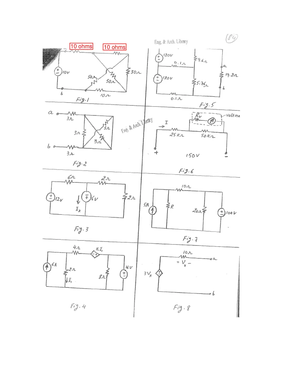
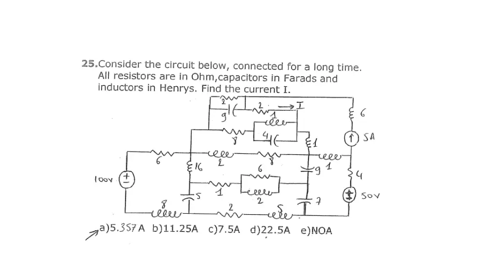

Showing the first 10 of 54 pages. Download the PDF to see all of it.
More EECE 210 files
- Exam 1 Questions and Answers · Fall 2015Problems · with solutionView
- Exam Questions and Answers · Fall 2015Problems · with solutionView
- Exam 2 Answer and Questions · Fall 2015Problems · with solutionView
- Problems After Quiz 3 · Summer 2013ProblemsView
- Problems Exam-Solution · Spring 2013Problems · with solutionView
- Problems For Quiz 1 · Spring 2012ProblemsView
- Problems For Quiz 3 · Fall 2012ProblemsView
- Problems For Quiz 1 · Fall 2012ProblemsView
Show the text of this problems
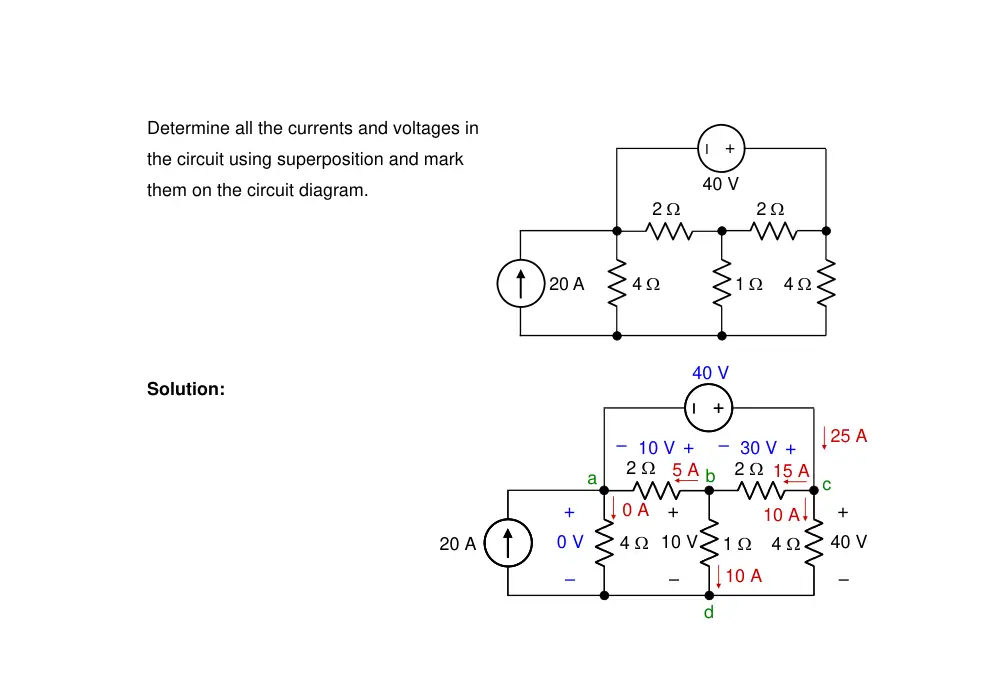
Determine all the currents and voltages in
the circuit using superposition and mark
them on the circuit diagram.
–
+
20 A
2 Ω
2 Ω
4 Ω
4 Ω
1 Ω
40 V
–
+
–
+
+
–
20 A
2 Ω
2 Ω
4 Ω
4 Ω
1 Ω
40 V
+
–
10 V
a
b
c
d
10 A
10 A
+
– 30 V
15 A
25 A
5 A
+
– 10 V
40 V
0 A
+
–
0 V
Solution:
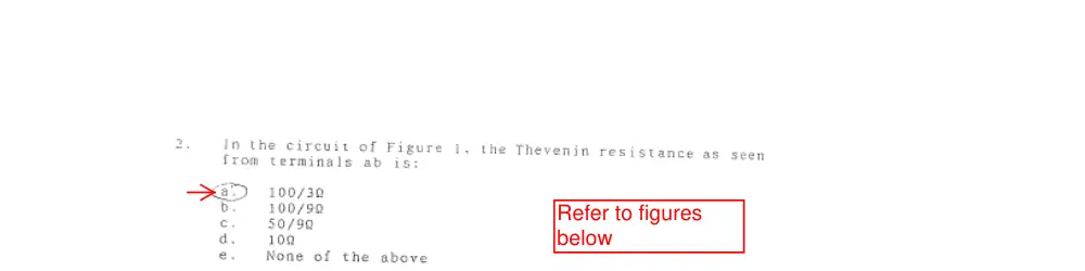
Refer to figures
below
10 ohms
10 ohms
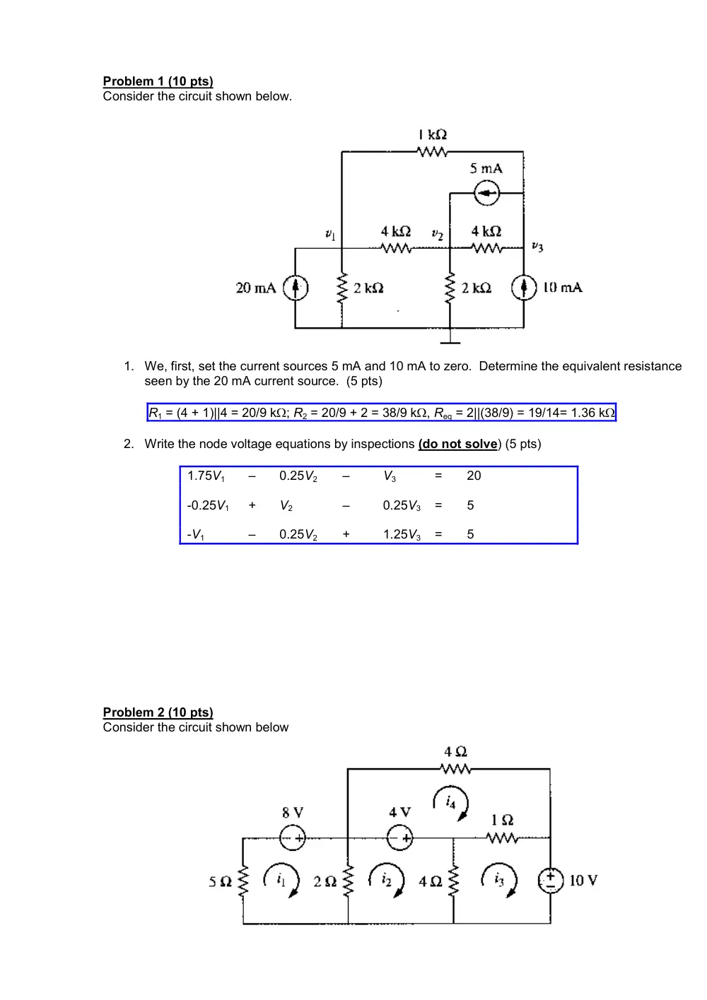
Problem 1 (10 pts)
Consider the circuit shown below.
1. We, first, set the current sources 5 mA and 10 mA to zero. Determine the equivalent resistance
seen by the 20 mA current source. (5 pts)
R1 = (4 + 1)||4 = 20/9 kΩ; R2 = 20/9 + 2 = 38/9 kΩ, Req = 2||(38/9) = 19/14= 1.36 kΩ
2. Write the node voltage equations by inspections (do not solve) (5 pts)
1.75V1
–
0.25V2
–
V3
=
20
-0.25V1
+
V2
–
0.25V3
=
5
-V1
–
0.25V2
+
1.25V3
=
5
Problem 2 (10 pts)
Consider the circuit shown below
1. We, first, set the 4V source and the 10V source to zero. Determine the equivalent resistor seen by
the 8V voltage source. (5 pts)
Req = 5 + (2||4||4||1) = 5 + 0.5 = 5.5 Ω
2. Write the mesh-current equations. (do not solve). (5 pts)
7I1
–
2I2
–
0I3
–
0I4
=
8
-2I1 +
6I2
–
4I3
–
0I4
=
4
0I1
–
4I2
+
5I3
–
I4
=
-10
0I1
–
0I2
–
I3
+
5I4
=
-4
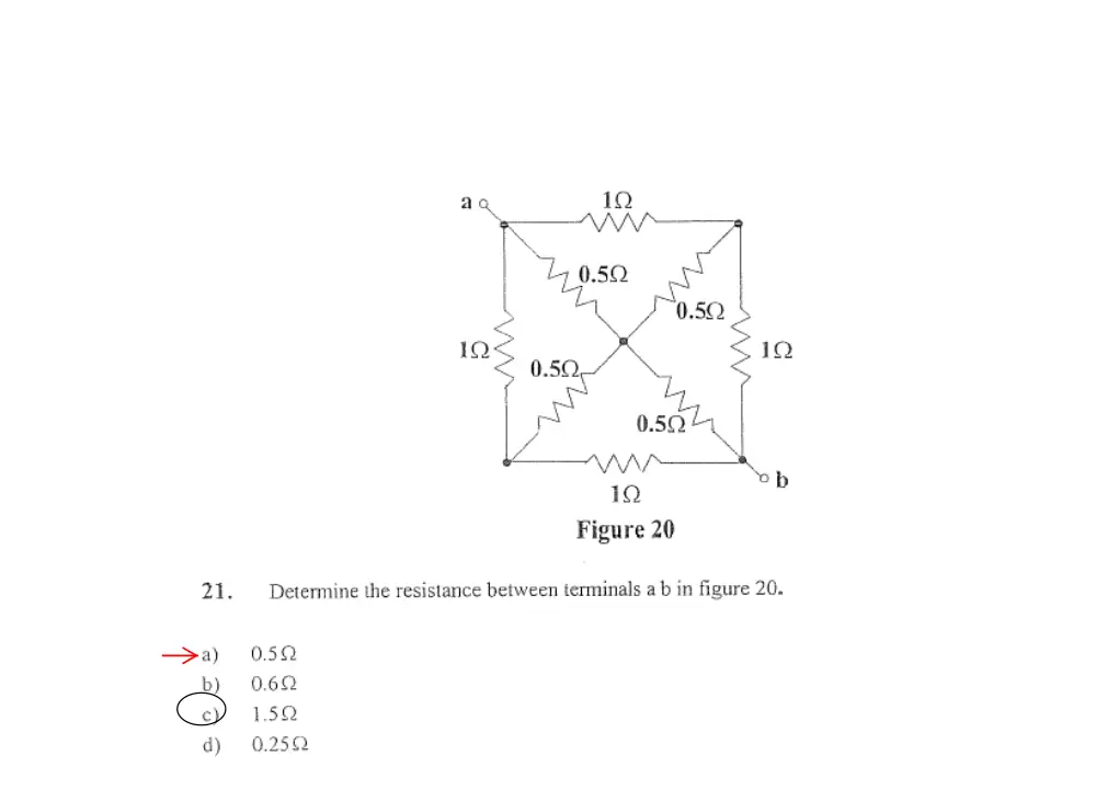
1. Determine the equivalent resistance between
terminals a and b, given that all resistances are 1 Ω.
A. 5 Ω
B. 4.5 Ω
C. 4 Ω
D. 3 Ω
E. None of the above
Solution: The resistances not connected directly to
terminals a and b form a balanced bridge. Hence the resistance across the bridge does
not carry any current and can be replaced by an open circuit or a short circuit. If replaced
by an open circuit, Req = 1 + 2||2 + 1 = 3 Ω.
a
b
Problem 2
Find the power
consumed by the 50
ohm resistor in the
circuit shown below
A) P= 0.246 W
B) P= 0.692 W
C) P= 2.358 W
D) P= 5.100 W
E) None of the
above
Problem 6
Given the circuit above, determine the current Ix if voltage-controlled current source has B=0.2:
A) 0
B) 0.285
C) 1.285
D) 0.5
E) None of the above
7
Problem 11
What is I0?
A) 1 A
B) -1 A
C) 2 A
D) -2 A
E) None of the above
Problem 5
a
b
c
d
IB
IA
IC
R1
R2
R3
The following values are given:
IA= 1 mA, IB= 2 mA, IC = 4 mA, R1 = R2 = R3 = 1 kΩ,
What is the value of Vbc?
A) 4 V
B) -2 V
C) 1 V
D) 5 V
E) None of the above
Problem 9
Find Ix.
A) 4.2 A
B) 3.5 A
C) 2.25 A
D) 4.75 A
E) None of the above
Problem 10
Find the Thevenin equivalent across terminals a and b.
A) RTH = 40Ω, VTH = 6.67 V
B) RTH = 40Ω, VTH = -6.67 V
C) RTH = 80Ω, VTH = 12 V
D) RTH = 80Ω, VTH = -12 V
E) None of the above
20 V
20 Ω
30 Ω
20 Ω
Problem 11
Find the current, I0, flowing through the dependant source.
A) 9.4A
B) 14A
C) -3A
D) -12A
E) None of the above.
Problem 12
Find the voltage, V, across the 2A source.
A) 400 V
B) 140 V
C) 6 V
D) -300 V
E) None of the above
P3.1.25
Determine VO in F
P3.1.25 using node
voltage analys
ig.
-
is.
Va
3.1.26
Determine VO in Fig. P3.1.25 using mesh-current analysis.
I1 = 10 and
3 – I4 = 10. For mesh 4:
A, I3 = 0, and I4 = 0,
Figure P3.1.25
10 A
2 Ω
– +
+
–
+
–
2Vx
20 V
+
–
Vx
2 Ω
2 Ω
4 Ω
4 Ω
+
–
VO
Solution: The node-voltage
equation for node a is: Va –
0.5Vb – 0.5Vc = 10; substituting
Vb = 20 V: Va – 0.5Vc = 20. For
node c: -0.5Va + 0.75Vc = -Iy;
for node d: -0.5Vb + 0.75Vd =
Iy; adding and substituting for
Vb: -0.5Va + 0.75Vc + 0.75Vd =
10. For the dependent source:
Vd – Vc = 2Vx = 2Vb – 2Va, or 2
10 A
2 Ω
– +
+
–
2Vx
20 V
+
–
Vx
2 Ω
2 Ω
4 Ω
4 Ω
+
–
VO
a
b
c
d
Iy
– Vc + Vd = 40. Solving, Va = 40 V, Vc = 40 V, Vd = VO = 0.
P
Solution For mesh 2:
+
–
V
-2I1 + 6I2 – 2I4 =
10 A
2 Ω
– +
+
–
2Vx
20 V
x
2 Ω
2 Ω
4 Ω
4 Ω
-2Vx; substituting
Vx = -2I2: I2 – I4 = 10. For
mesh 3: -4I1 + 8I3 – 4I4 =
2Vx;
I2 + 2I
-2I2 – 4I3 + 6I4 = -20, or -I2 –
2I3 + 3I4 = -10. Solving, I2 =
10
which gives VO = 0.
+
–
VO
I2
I1
I4
I3
P3.2.12
Determine VO in Fig. P3.1.19 using
superposition and calculate the
power dissipated in the 5 Ω
resistor.
Figure P3.1.19
2 A
4 A
2 Ω
4 Ω
4 Ω
2 Ω
5 Ω
+
VO
– +
3VO V
–
2 A
2 Ω
4 Ω
4 Ω
5 Ω
+
VO
– +
3VO V
–
Solution: With the 2 A source acting alone, the
circuit becomes as shown. The source current
flows through the 5 Ω resistor, so that VO1 = 10
V. Similarly, when the 4 A source is applied
alone, VO2 = 20 V. From superposition, VO =
VO1 + VO2 = 30 V. The dependent source does
not contribute to VO.
Power dissipated in the 5 Ω resistor is
180
5
(30)
2
=
W.
P3.2.13
Determine IO
in Fig.
P3.1.21 using
superposition
and calculate
the power
dissipated in
the 5 S
resistor.
Figure P3.1.21
4 S
2 V
5 S
IO
4 S
+
–
+
–
+
–
+
–
3IO
4 V
2 S
2 S
Solution: With the 2 V
source acting alone, and the
4 V source replaced by a
short circuit, the circuit
becomes as shown. The
source voltage is applied
across the 5 S resistor, so
that IO1 = 10 A. Similarly,
when the 4 V source is applied alone, IO2 = 20 A. From superposition, IO = IO1 + IO2 = 30 A. The
dependent source does not contribute to IO. Power dissipated in the 5 S resistor is
180
5
(30)
2
=
W.
4 S
2 V
5 S
IO
4 S
+
–
3IO
2 S
2 S
P4.1.8
Derive TEC between terminals ab in Fig. P4.1.8.
Figure P4.1.8
1 A
1 A
10 Ω
10 Ω
20 Ω
a
b
Solution: Let us first remove the 20 Ω resistor and reapply it
later. On open circuit, each 1 A source produces a 10 V
drop across the resistor in parallel with it. Hence Voc1 = 20 V.
On short circuit, Isc = 1 A, so that RTh1 = 20 Ω. When the 20
Ω resistor is added at terminals ab, VTh = 20×(20/40) = 10 V
and RTh = (20||20) = 10 Ω
P4.1.9
Derive TEC between terminals ab in Fig. P4.1.9.
Solution: On open circuit, KVL around the upper mesh
gives 20Ix = 20, or Ix = 1 A. It follows that VTh = Voc = 20
+ 20Ix = 40 V.
On short circuit, the current in the 10 Ω resistor is 2 A.
KVL around the upper mesh gives: 20 = 5(Ix – Isc) +
5(3Ix – Isc), or 2Ix – Isc = 2; from KCL at node c: 3Ix – Isc +
2 = Ix, or 2Ix – Isc = -2. This means that Ix and Isc are
indeterminate. This suggests that RTh = 0, which would
make Isc indeterminate. To verify this, we apply a test
source of 1 A, with the voltage source set to zero. Then, 4Ix + 2 = 0, so that Ix = -0.5 A and VT =
2(-0.5) + 1 = 0. Hence RTh = 0.
5 Ω
5 Ω
10 Ω
a
b
– +
20 V
2Ix
Ix
Ix
3Ix
2Ix
5 Ω
5 Ω
10 Ω
a
b
– +
20 V
2Ix
Ix
Ix – Isc
2 A
Isc
3Ix – Isc
c
5 Ω
5 Ω
10 Ω
a
b
2Ix
Ix
+
–
VT
1 A
Ix + 1
3Ix + 1
2Ix + 1
P4.1.10
Derive NEC between the short-circuited
terminals ab in Fig. P2.1.4.
Solution: If a test voltage is applied, KCL at node a
gives Iφ = IT + 3. From KCL at node c, IT + 3 + 10 =
5, or IT = −8 A, irrespective of VT. It follows that IN =
8 A. Since IT is independent of VT, it means that
there is no resistance in parallel with the current
source IN.
Figure P2.1.4
–
+
–
+
Ix
3 A
10 A
5 A
10 V
10 V
a
b
–
+
–
+
IT
3 A
10 A
5 A
10 V
10 V
a
b
–
+
VT
Iφ
c
P4.1.11
Determine VO in Fig. P3.1.7 using
TEC.
Figure P3.1.7
–
+
–
+
10 V
10 Ω
20 Ω
40 Ω
80 Ω
20 V
+
–
VO
Solution: Open-circuit voltage: When only the
10 V source is applied, VTh1 =
3
10
10
30
10
=
×
V.
When only the 20 V source is applied VTh2 = 20
V. Hence, VTh = 70/3 V. With both sources set
to zero, RTh = 10||20 = 20/3 Ω. It follows that VO
=
20
3
70
20 / 3
40
40
=
×
+
V.
–
+
–
+
10 V
10 Ω
20 Ω
80 Ω
20 V
a
b
P4.1.12
Determine IO in Fig. P3.1.9
using NEC.
Figure P3.1.9
10 A
IO
20 A
a
b
c
80 S
10 S
20 S
40 S
Solution: With the 10 A source acting
alone, IN1 =
3
10
10
30
10
=
×
A. With the 20
A source acting alone, IN2 = 20 A.
Hence, IN = 70/3 A.
10 A
IN
20 A
a
b
c
80 S
10 S
20 S
The conductance between terminals bc
is
3
20
10
20
10
20
=
+
×
S. It follows from NEC
that
20
3
70
20 / 3
40
40
=
×
+
=
OI
A.
P4.1.15
Determine VO in Fig. P3.1.15
using TEC.
Figure P3.1.15
–
+
10 V
2 Ω
2 Ω
4 Ω
5Ix A
4 Ω
IX
–
+
VO
–
+
10 V
2 Ω
2 Ω
5ISC
4 Ω
ISC
Solution: On open circuit, Ix = 0, and the
dependent source becomes an open circuit. It
follows that VTh = 10 V. On short circuit, the
circuit becomes as shown, where Ix = ISC and the
dependent source becomes 5ISC. It follows from
KCL that:
4
10
5
+
=
SC
SC
I
I
, which gives
8
ISC = − 5
A, and
SC = −16 Ω. Hence
R
3
10 = − 10
16
4
4
×
−
VO =
V.
P4.1.16
Determine IO in Fig. P3.1.17
using NEC.
Figure P3.1.17
4 S
10 A
4 S
5Vx
+
–
2 S
2 S
+
–
Vx
IO
4 S
10 A
5Voc
+
–
2 S
2 S
+
–
Voc
10 A
Solution: On open circuit, 10 A flows
through the 4 S resistor, so that Voc = 5Voc
4
+ 10
, which gives
8
Voc = − 5
A. On short
circuit, Vx = 0 and the dependent source is
zero, so that IN = 10 A. This makes
N = −16 S. It follows that
G
=
×
−
=
16
4
4
OI
10
3
− 10
A.
P4.1.17
Determine VO in Fig. P3.1.19
using NEC.
Solution: If the 5 Ω resistor is replaced by an
open circuit, the circuit is invalid, as two
unequal current sources will be connected in
series through the 2 Ω resistors, and
. If a test source is applied in place of
the 5 Ω resistor and the current sources
replaced by open circuits, the resistance seen
by the source is infinite. If the 5 Ω resistor is
replaced by a short circuit, ISC = 6 A. It follows that the circuit does not possess a TEC between
the specified terminals, only an NEC consisting of an ideal current source of 6 A. This gives VO
= 30 V.
O → ∞
V
Figure P3.1.19
2 A
4 A
2 Ω
4 Ω
4 Ω
2 Ω
5 Ω
+
VO
– +
3VO V
–
P4.1.18
Determine IO in Fig. P3.1.21 using TEC.
Solution: If the 5 S
resistor is replaced by a
short circuit, the circuit is
invalid, as two unequal
voltage sources will be
connected in series, and
. If a test source
is applied in place of the
5 S resistor and the
voltage sources
replaced by short
circuits, the resistance seen by the source is zero. If the 5 S resistor is replaced by an ope
circuit, VTh = 6 V. It follows that the circuit does not possess an NEC between the specified
terminals, only a
→ ∞
OI
Figure P3.1.21
4 S
2 V
5 S
IO
4 S
+
–
+
–
+
–
+
–
3IO
4 V
2 S
2 S
n
TEC consisting of an ideal voltage source of 6 V. This gives IO = 30 A.
P4.1.19
Determine IO in Fig. P3.1.23
using NEC.
Figure P3.1.23
–
+
10 V
4 S
2 S
2 S
4 S
2 S
2 A
IO
2Ix
Ix
Solution: With the 4 S resistor replaced
by a short circuit, IO can be obtained
from mesh-current analysis. The mesh
current equations are the same as those
for P3.1.24 but with a coefficient of 0.5
for I4 in the equation for mesh 4. The
equations are:
–
+
10 V
4 S
2 S
2 S
2 S
2 A
IN
2Ix
Ix
I2
I1
I3
I4
I1 – 0.5I2 = 9; -0.5I1 + 0.75I2 + 0.5I4 = -1;
and 2I1 – I2 + I4 = -4. Solving, I4 = IO = -
22 A.
If a test source is substituted for the 4 S
resistor, with the independent source set to
zero, it is seen from KCL at the middle node
that IT = 0, which means that the source
resistance is infinite. The circuit does not
possess a TEC between the specified
terminals, only an NEC.
–
+
–
+
4 S
2 S
2 S
2 S
Ix
2Ix
Ix
IT
VT
P4.1.20
Determine VO in
Fig. P3.1.25 using
TEC.
Figure P3.1.25
10 A
2 Ω
– +
+
–
+
–
2Vx
20 V
+
–
Vx
2 Ω
2 Ω
4 Ω
4 Ω
+
–
VO
2 Ω
+
–
2Vx
+
–
Vx
2 Ω
2 Ω
4 Ω
+
–
VO
IT
a
b
c
d
+
–
Vx
Solution: If a current source is applied at node d,
with the independent sources set to zero, it is seen
that Vac = Vx, so that Vbd = 0 and VO = 0. In other
words the source sees a short circuit and Rsrc = 0.
If the resistor between node d and the reference node
is replaced by an open circuit, the node-voltage
equation at node a is:
, and the node
voltage equation at node c is: -0.5Va + 0.75Vc = -Iy,
where Iy =
. Substituting for
Iy: 0.25Va + Vc = 30. Solving,
gives Va = Vc = 40 V. Hence, Vx
= 20 V and Vd = 0. In other
words, TEC and NEC are just
short circuits,
20
0.5
=
−
c
a
V
V
(
) =
−
+
20
2
0.5
x
c
V
V
30
0.5
−
+
a
c
V
V
10 A
2 Ω
– +
+
–
2Vx
20 V
2 Ω
2 Ω
4 Ω
+
–
VO
a
b
c
d
Iy
1. Determine VO assuming ISRC = 0.25 A.
A. 4 V
B. 1 V
C. 5 V
D. 2 V
E. 3 V
Solution: The two 5 Ω resistances can be
combined in parallel to give a 2.5 Ω resistance,
and the two 10 Ω resistances can be combined
in parallel to give a 5 Ω resistance carrying a
current of 2Ix, as shown. It follows that ISRC – 2Ix =
0.5Ix, or
.5
2
SRC
x
I
I
=
and
, so that
.
x
O
I
V
10
=
SRC
O
I
V
4
=
_
+
VO
ISRC
0.5Ix
10 Ω
5 Ω
5 Ω
Ix
10 Ω
_
+
VO
ISRC
0.5Ix
2.5 Ω
2Ix
5 Ω
2. Determine ISRC assuming VSRC = 2 V and all resistances
are 2 Ω.
VSRC
ISRC
A. 1.5 A
B. 3 A
C. 2.5 A
D. 2 A
E. 1 A
Solution: From symmetry the two currents Ix are equal and
sum to zero. Hence, Ix = 0 and the two resistors can be
removed. The equivalent resistance seen by the source is
(2 + 2)||(2 + 2) = 2 Ω. It follows that ISRC = VSRC/2.
VSRC
ISRC
Ix
Ix
1/5
3. Determine VO assuming ISRC = 1 A.
A. 7.5 V
_
+
VO
ISRC
5 Ω
10 Ω
5 Ω
ISRC
B. 12.5 V
C. 5 V
D. 15 V
E. 10 V
_
+
VO
5 Ω
10 Ω
5 Ω
ISRC
Solution: The two current sources are equivalent to a current
source ISRC connected as shown, since KCL is the same at the two
nodes. The resistance seen by the source is 10||(5 + 5) = 5 Ω.
Hence, VO = 5ISRC.
4. Determine Thevenin’s resistance looking into terminals ab, assuming α = 10.
A. 50 Ω
B. 25 Ω
–
+
5 V
2 kΩ
–
+
+
–
a
b
αIx
2VO
RL
Ix
VO
C. 100 Ω
D. 200 Ω
E. 20 Ω
Solution: When a test source VT is
applied at terminals ab, with the
independent voltage source set to zero,
it follows from the circuit that:
T
O
O
x
V
V
V
I
= −
= −
= −
2
2
mA. IT = -αIx =
αVT mA. Hence,
α
α
1000
1 kΩ
≡
=
T
T
I
V
Ω.
2 kΩ
–
+
+
–
a
b
αIx
2 VO
Ix
VO
–
+
VT
IT
2/5
–
+
–
+
V1
2 A
4 Ω
6 Ω
3 Ω
2 Ω
4 Ω
–
+
V2
Vx
5. Determine V2 so that Vx = 0, assuming
V1 = 4 V.
A. 8 V
B. 6 V
C. 6.5 V
D. 7.5 V
E. 7 V
Solution: The 6 Ω and 3 Ω resistors do not
carry any current. They can removed from
the circuit, with nodes a and b being at the
same voltage. V1 can be transformed to a
current source V1/4 A in parallel with a 4 Ω
resistor. The total current is (0.25V1 + 2) A in
parallel with 2 Ω. V2 is the voltage of node a,
which gives: V2 = 2(0.25V1 + 2) = (0.5V1 + 4)
V.
–
+
–
+
V1
2 A
4 Ω
2 Ω
4 Ω
V2
a
b
6. Derive the mesh current equations in terms of I1, I2, and I3. DO NOT SOLVE THE
EQUATIONS
20 Ω
5 Ω
5 Ω
Ix
15 Ω
12 V
–
+
10 Ω
I1
I2
I3
6 A
2Ix
a
b
Solution: Considering the voltage drop Vab
as a unit, the equation for mesh 1 is:
(10 + 5)I1 – 5I3 = 12 – Vab
The mesh-current equation for mesh 2 is:
(20 + 5)I2 – 5I3 = Vab
Adding these two equations:
15I1 + 25I2 – 10I3 = 12
The remaining equations are:
I3 = 6, and
I2 – I1 = 2Ix = 2(I2 – I3), or
I1 + I2 – 2I3 = 0
Note that if the 15 Ω resistor is denoted by R and the conventional mesh-current procedure
is applied, the term in R cancels out. Thus, for mesh 1:
3/5
(10 + 5 + R)I1 – RI2 – 5I3 = 12 – Vx, where Vx is the voltage drop across dependent current
source in the direction of I1. For mesh 2, -RI1 + (20 + 5 + R)I2 – 5I3 = Vx. Adding these two
equations gives the same equation as before.
If these equations are solved, I1 = 22.8 A, I2 = -10.8 A, Ix = -16.8 A, Vx = -804 V.
–
+
–
+
10 V
6 A
6 Ω
3 Ω
4 Ω
1V
a
b
2 Ω
2 Ω
4 Ω
Ix
–
+
2Ix
7. Determine Thevenin’s
equivalent circuit seen
between terminals a and b
Solution:
Method 1: Leave the circuit
as it is. Considering the
mesh on the RHS, 1 = 3Ix +
4Ix + Vcb, where Vcb = 10 +
2Ix. Substituting for Vcb gives
Ix = -1 A, so that VTh = 4 V.
Applying a test
source with the independent
sources set to zero, the
branch containing the 6 A
source is open circuited.
The 6 Ω and 4 Ω resistors are in parallel
with one terminal at node b and the other
terminal connected to an open circuit.
They do not carry any current and can be
removed. The circuit reduces to that
shown. VT = 4Ix + 2Ix = 6Ix, and IT = Ix +
VT/3. Substituting for Ix gives VT/IT = RTh =
2 Ω.
–
+
–
+
10 V
6 A
6 Ω
3 Ω
4 Ω
1V
a
b
2 Ω
2 Ω
4 Ω
Ix
–
+
2Ix
Vcb
c
+
–
–
+
a
b
4 Ω
Ix
VT
2Ix
IT
3 Ω
2 Ω
4/5
If terminals ab are
short circuited, KVL around
the outermost loop gives:
10 + 2Ix + 4Ix = 0, so that Ix
= -5/3 A; Isc = -Ix + 1/3 = 2
A. It follows that RTh = 4/2
= 2 Ω.
–
+
–
+
10 V
6 A
6 Ω
3 Ω
4 Ω
1V
a
b
2 Ω
2 Ω
4 Ω
Ix
–
+
2Ix
Vcb
c
+
–
Isc
1/3 A
Method 2: If the branch consisting of the 1 V source in series
with 3 Ω is removed, Ix = 0, the dependent source becomes a
short circuit, and the open-circuit voltage between terminals a
and b is the same as that of the 10 V source. Hence VTh1 = 10
V.
–
+
a
b
4 Ω
IT
IT
2IT
If a test current source IT is applied between terminals a
and b, with the independent sources set to zero, as before, and
the 2 Ω resistor removed because it is in parallel with the 2Ix
ideal voltage source and is redundant as far as Vab is
concerned, the circuit reduces to that shown. The 2IT CCVS is
equivalent to a 2 Ω resistor, which in series with the 4 Ω
resistor gives RTh1 = 6 Ω.
When the branch between terminals a and b is
reintroduced, the circuit becomes as shown. With terminals a
and b open circuited, the current in the circuit is 1 A in the direction shown and Vab = 4 V. If
the voltage sources are set to zero, the resistance seen between terminals ab is (6||3) = 2 Ω.
Hence, VTh = 4 V and RTh = 2 Ω.
–
+
3 Ω
1V
a
1 A
–
+
6 Ω
10 V
5/5
Problem 3
Find Ix.
−
+
10V
2KΩ
+−
5V
10Ω
2Ω
5Ω
10Ω Ix
−
+
5Ix
A) 230.8A
B) 76.92A
C) -76.92A
D) -230.8A
E) None of the above
Problem 4
Find Vx.
6A
0.25Vx
80Ω
−
Vx
+
10Ω
20Ω
16Ω
Ix
−
+
120V
− +
3Ix
A) 130.9V
B) -43.64V
C) 43.64V
D) -130.9V
E) None of the above
-76.92 mA
Problem 5
Find the power associated with the current source.
−
+
160V
4Ω
5A
16Ω
32Ω
16Ω
32Ω
A) 256W
B) -200W
C) 200W
D) -256W
E) None of the above
Problem 6
In the circuit below R1 is chosen such that I3 = 1A. Find R1.
−
+
100V
R1
I1
75Ω
I3
25Ω
I2
A) 12.5Ω
B) 16Ω
C) 25Ω
D) 6.25Ω
E) None of the above
176.9 W absorbed
Problem 7
Find Ix.
−
+
100V
10Ω
10Ω
10Ω
−+
20V
−
+
30V
Ix
A) -6A
B) 6A
C) 16A
D) -16A
E) None of the above
Problem 8
Find I0.
2I0
25Ω
50Ω
I0
20Ω
−
+
38.5V
100Ω
200Ω
5Ω
−
+
5I0
A) 1.15A
B) -0.65A
C) -1.15A
D) 0.65A
E) None of the above
Problem 9
Find the Thevenin equivalent resistance between a and b.
0.4A
4KΩ
12KΩ
Ix
−
+
500Ix
500Ω
a
1KΩ
b
A) 333.33Ω
B) 250Ω
C) 83.33Ω
D) 740.46Ω
E) None of the above
Problem 10
Find the Thevenin equivalent voltage between a and b (Vab).
−
+
2V
2KΩ
a
1KΩ
2mA
1KΩ
3KΩ
− +
4V
6mA
2KΩ
2mA
+
Vab
−
b
Vab = -1 V
Problem 11
Find the Thevenin equivalent resistance between a and b of the previous figure.
A) 6KΩ
B) 8KΩ
C) 4.5KΩ
D) 1.5KΩ
E) None of the above
Problem 12
Find the Thevenin equivalent resistance between a and b.
100A
250KΩ
−
+
100V
50Ω
a
20Ω
b
60Ω
I0
40Ω
−
+
60I0
A) 6Ω
B) 8.52Ω
C) 14.28Ω
D) 10.52Ω
E) None of the above
Problem 4
Find V1.
−
+
5V
2Ω
6V1
2Ω
2Ω
+
V1
−
−
+ 6V
A
B
A) -1.22V
B) 1.22V
C) -1.57V
D) 1.57V
E) None of the above
Problem 5
Find the Thevenin Equivalent Voltage between A and B (VAB).
I
R
i1
− +
R · i1
R
I
R
B
A
A) RI
B) -3RI
C) -RI
D) 3RI
E) None of the above
Problem 6
Find the Norton equivalent resistance between A and B.
R
R
R
I1
−+
V1
I2
+−
V2
B
A
A) 3R
B) 3R/2
C) R/3
D) R
E) None of the above
Problem 7
Find the Norton equivalent current source between A and B.
R
R
R
I
R
R
R
R
R
R
R
I
A
B
A) -2.28I(A)
B) -1.24I(A)
C) -3.21I(A)
D) -6.42I(A)
E) None of the above
1. The current components in a resistor R, as found from superposition, are -8 A and +4 A.
Determine the power dissipated in the resistor if R = 2 Ω.
Solution: The magnitude of the current through R is 4 A. The power dissipated in R is 16R =
32 W.
2. Determine IO if VS = 1 V.
Solution: The two terminals
of the 5 Ω resistor are at the
same voltage. Hence, this
resistor carries no current and
can be removed. The 1 Ω in
series with VS can be split into
two parallel branches, each of
2 Ω in series with VS. The
circuit can then be split into two halves as shown. It
follows that
4
5
S
O
V
I
−
=
= 1 A.
3. Determine R so Norton’s current between terminals a
and b is zero, given that ISRC = 5 A and α = 1 V/A.
Solution: If a and b are short-circuited and no current
flows in the short circuit, ISRC flows through R. Applying
KVL, RISRC = αISRC, which gives R = α = 1 Ω.
4. Determine Norton’s current at terminals a
and b, assuming ISRC = 0.5 A.
Solution: When terminals ab are short
circuited, VX = 0 and the dependent voltage
source 0.5VX is zero, so that IN = ISRC = 0.5 A.
10 Ω
5 Ω
ISRC
–
+
αISRC
a
b
R
–
+
5 V
–
+
–
+
5 V
VS
4 Ω
4 Ω
1 Ω
2 Ω
2 Ω
5 Ω
IO
–
+
–
+
5 V
VS
4 Ω
2 Ω
2 Ω
IO
ISRC
–
+
0.5VX
–
+
5 Ω
10 Ω
2Io
Io
a
b
+
–
VX
–
+
VSRC
2 kΩ
–
+
+
–
a
b
2Ix
2VO
RL
Ix
VO
5. Determine the power delivered by the source,
assuming all resistances are 1 Ω and VSRC = 1 V.
Solution: From symmetry, each top node along the
same vertical line is at the same voltage as the
corresponding bottom node. Joining these nodes
together simplifies the circuit to that shown. The
resistance on each side of the source is 0.5||2 Ω =
0.4 Ω. Hence, ISRC = VSRC/0.8 A and the power
delivered by the source is
.8
0
2
VSRC
=
1.25
0.8
1 =
W.
6. Determine VX assuming VS = 1 V.
Solution: With the 4 V source applied alone, and
VS set to zero,
2
4
4 || 4
2
2
1
=
×
+
VX =
V. With VS
applied and the 4 V source set to zero,
4
4 / 3
4
4 / 3
2 || 4
4
2 || 4
2
S
S
S
X
V
V
V
V
= −
×
+
= −
×
+
= −
; VX
=
4
2
− VS
1 75
4
1
2
= .
−
=
V.
7. Determine Thevenin’s voltage between
terminals a and b, with RL removed,
assuming VSRC = 5 V.
Solution: When terminals ab are open
circuited, IX = 0. To make IX = 0, 2VO =
VSRC, so that VTh = VSRC/2 = 2.5 V.
8. Determine the power delivered by
ISRC assuming ISRC = 0.5 A.
–
+
VSRC
1 Ω
1 Ω
0.5 Ω
0.5 Ω
0.5 Ω
0.5 Ω
0.5 Ω
0.5 Ω
–
+
2 Ω
2 Ω
4 Ω
4 Ω
1 Ω
–
+
2 Ω
4 V
VS
+
–
VX
–
+
VSRC
_
+
6 V
6 Ω
3 Ω
5 Ω
ISRC
1 Ω
Solution: To determine Vab, the 5 Ω and 1 Ω
resistances are redundant. Transforming the
voltage source to a current source, it follows that
Vab = 2(2 + ISRC) From the original circuit, the
voltage rise across the current source is Vab +
1×ISRC = 3ISRC + 4, and the power delivered is P =
ISRC(3ISRC + 4) = 2.75 W.
9. Determine VTh assuming VS = 1 V and R = 2 Ω.
Solution: Let VX be the voltage drop Vdc. Applying
KCL to node d:
2
4
8
6
3
=
+
+
+
X
X
X
V
R
V
R
V
; this gives VX = 0, so
that Vef = 0 and VTh = VS = 1 V.
Alternatively, if the subcircuit between nodes c
and d is removed, Vdc in this circuit is zero, and
Vdc in the bridge is zero, which makes Vef = 0
and VTh = VS.
10. Determine RTh in the preceding problem.
Solution: If a test source is applied with all
independent sources set to zero, the
circuit reduces to that shown, where the
current in the 4 Ω resistor is zero. It
follows that RTh = 3R||6R = 2R = 4 Ω.
+
–
+
–
a
b
+
–
VTh
4 Ω
2 A
8 V
VS
R
2R
2R
4R
+
–
+
–
a
b
+
–
VTh
4 Ω
2 A
8 V
VS
R
2R
2R
4R
+
–
VX
VX /6R
VX /3R
d
c
e
f
+
–
4 Ω
2 A
8 V
+
–
8 V
c
d
R
2R
2R
4R
d
c
a
b
4 Ω
–
+
VT
IT
_
+
6 V
6 Ω
3 Ω
ISRC
a
b
11. For the circuit shown, write the circuit equations in terms
of the node voltages Va, Vb, and Vc. You are not
required to solve these equations.
Solution: The circuit is redrawn as shown with the
redundant 2 S resistor removed and the three 3S resistors
combined into a 1 S resistor.
For node a: Va = 0.5IX, where, for node b, IX = 5 –
1×Vb. Substituting and rearranging, 2Va + Vb = 5. For node
c: -2Va + 6Vc = IX = 5 – Vb; or -2Va + Vb + 6Vc = 5. The third
equation is: Vb – Vc = 10.
12. Use the substitution theorem and
superposition to determine Vy, where
R is unknown.
Solution: In accordance with the
substitution theorem, R can be replaced
by a 0.5 A current source. With this
current source set to zero, Vy1 =
17.5
225
30
17.5
7.5
= −
×
−
V. With the 30 V
source set to zero and the 0.5 A current
source applied, Vy2 =
17.5
37.5
7.5
0.5
17.5
10
= −
×
×
−
V. It follows that Vy = Vy1 + Vy2 =
15
17.5
262.5
17.5
37.5
225
= −
= −
+
−
V.
30 V
–
+
0.5 A
18 Ω
8 Ω
10 Ω
7.5 Ω
R
Vy
10 V
+
–
5 A
–
+
0.5Ix
2 S
4 S
1 S
Ix
a
b
c
10 V
+
–
5 A
–
+
0.5IX
2 S
2 S
4 S
3 S
3 S
3 S
IX
a
b
c
1
–
+
12 V
a
b
c
d
13. Determine Thevenin’s equivalent circuit
between terminals ab, assuming all
resistances are 5 Ω.
Solution: With the 5 A source applied
alone, it follows from symmetry that VTh1 = 0.
With the 12 V source applied alone, it
follows from symmetry (as in Example
4.5.1a) that the middle nodes are all at the
same voltage. The circuit reduces to that shown,
where the effective resistance between nodes c and
d is 10||20 = 20/3 Ω, so that Vcd =
V, and VTh =
V. Alternatively, VTh can be found by
scaling.
To determine RTh, with the two sources set to zero, it
follows again from Example 4.5.1a that the middle nodes are at
the same voltage so that the horizontal resistor in the middle
carries no current and can be removed. With the 12 V source
replaced by a short circuit, the circuit reduces to that shown. It
follows that the effective resistance between nodes c and d is 5
Ω, and RTh = 15||10 = 6 Ω.
1. Determine Thevenin’s equivalent circuit (TEC)
looking into terminals ab, assuming VSRC = 5 V and
ISRC = 2 A.
A. VTh = 12 V, RTh = 2 Ω
B. VTh = 15 V, RTh = 6 Ω
C. VTh = 12 V, RTh = 6 Ω
D. VTh = 15 V, RTh = 2 Ω
E. TEC does not exist
Solution: On open circuit, ISCR flows through the 6 Ω
resistor, so that VTh = 6ISRC. If a test source is applied with the voltage source replaced by
short circuit and the current source replaced by an open circuit, the resistance looking into
terminals ab is RTh = 6 Ω.
4.8
12
10
20 / 3
20 / 3
=
×
+
2.4
4.8
20
10
=
×
a
b
c
d
a
–
+
b
12 V
5 A
–
+
VSRC
3 Ω
6 Ω
a
b
ISRC
2
2. A circuit has 20 essential branches, 11 essential nodes and 10 meshes. How many
independent KCL equations can be written for this circuit?
A. 8
B. 6
C. 7
D. 10
E. 9
Answer: The number of independent KCL equations is one less than the number of
essential nodes.
3. How many independent KVL equations can be written for the circuit of the preceding
question?
A. 11
B. 10
C. 9
D. 12
E. 13
Answer: The number of independent KVL equations is same as the number of meshes.
11. Determine IO
assuming all
resistances
are 1 Ω and
VSRC = 5 V.
Solution: Superposition can be applied. If the 10 V source is applied alone, with VSRC
replaced by a short circuit, the component of IO is zero. If VSRC is applied alone, IO is
determined by VSRC and what happens in the
circuit to the left of VSRC is not relevant to IO. The
resistor across VSRC is redundant, and the circuit
reduces to that shown. If scaling is applied,
assuming IO = 1 A, then Vcd = 3 V, Iac = Ibd = 4A,
Vab = 2×4×1 + 3 =11 V, ISRC = 15 A, and VSRC =
2×15×1 + 11 = 41 V. Hence, IO = VSRC×(1/41). Alternatively, VSRC can be divided into two
sources, and the left-hand part of the circuit reduces to that shown.
–
+
VSRC
1 A
–
+
3 A
3 V
4 A
–
+
11 V
11 A
15 A a
c
b
d
–
+
–
+
10 V
VSRC
IO
3
4. Determine VO.
A. 2 V
B. 4 V
C. 0
D. 1.5 V
E. 2.5 V
Solution: Since the circuit does not have any
independent sources, VO = 0. This can also be
shown by analyzing the circuit. Thus, 1.25Vx =
VO, so I1 = Vx/1 = VO/1.25 = 0.8VO; I2 = 0.5VO/2 =
0.25VO; IO = VO/5 = 0.2VO. Applying KCL, 0.8VO +
0.25VO + 0.2VO = 0, or 1.25VO = 0, so VO = 0.
5. Given that Va = 25 V and Vb = 12 V. Determine Va if
node b is grounded instead of c.
A. 13 V
B. 37 V
C. 14 V
D. 15 V
E. 16 V
Solution: When node b is grounded, Vb = 0. Hence, 12 V
is subtracted from all node voltages, and Va = 25 – 12 =
13 V. Alternatively, it can be argued that the voltage drop from a to b is 13 V irrespective of
which node is grounded.
6. The power dissipated in R is 8 W if ISRC is
applied alone, with VSRC set to zero, and is 0.5
W if VSRC is applied alone, with ISRC set to zero.
Determine the power dissipated in R if both
sources are applied together, with polarities that will give the largest current in R.
A. 8.5 W
B. 18 W
C. 24.5 W
D. 32 W
E. 12.5 W
–
+
–
+
–
+
VO
0.5VO
–
+
Vx
0.25Vx
5 Ω
2 Ω
1 Ω
I1
I2
IO
–
+
VSRC
2 Ω
R
ISRC
2 Ω
4
Solution: When ISRC source is applied alone, with VSRC set to zero, the current in R is
2
8/ 2
=
A. When VSRC is applied alone, with ISRC set to zero, the current in R is
Pv / 2
.
With both sources applied together to to give the largest current in R, the total current in R is
/ 2
2
V
P
+
and the power dissipated in R is
(
)
V
V
V
T
P
P
P
P
+
+
=
+
=
/ 2
8
8
/ 2
2 2
2
.
7. Determine Norton’s equivalent circuit
(NEC) looking into terminals ab,
assuming VSRC = 5 V and ISRC = 2 A.
A. IN = 2 A, RN = 5 Ω
B. NEC does not exist
C. IN = 3 A, RN = 5 Ω
D. IN = 4 A, RN = 5 Ω
E. IN = 2 A, RN = 0
Solution: On open circuit, VTh = VSRC. If VSRC and ISRC are set to zero, the resistance looking
into terminals ab is that of a short circuit, so RTh = 0. If terminals ab are short-circuited, IN →
∞. Hence, TEC is the ideal voltage source VSRC, and NEC does not exist.
8. Determine TEC looking into
terminals ab, assuming VSRC = 4 V.
A. VTh = 4 V, RTh = 75 Ω
B. VTh = 4 V, RTh = 300 Ω
C. VTh = 4 V, RTh = 100 Ω
D. VTh = 3 V, RTh = 300 Ω
E. VTh = 3 V, RTh = 75 Ω
Solution: The 1 kΩ resistor and the dependent current source are redundant because they
are in parallel with an ideal voltage source. The circuit reduces to a voltage source
connected to a 100 Ω-300 Ω voltage divider with terminals ab across the 300Ω resistor. It
follows that VTh = VSRC×300/400 = 3VSRC/4. If a test source is applied with VSRC replaced by a
short circuit, the resistance looking into terminals ab is RTh = 100||300 = 75 Ω.
Alternatively, if Ix is the current flowing in the 100 Ω resistor toward node a, with the output
open circuited, then Vφ = VSRC – 100Ix and Vφ = 300Ix. Eliminating Ix gives VTh = Vφ = 3VSRC/4.
VSRC
–
+
ISRC
5 Ω
a
b
–
+
VSRC
0.5Vφ
1k Ω
a
b
100 Ω
300 Ω
–
+
Vφ
5
1. Determine, according to the substitution theorem,
which of the following ideal circuit elements can
replace the dependent source without affecting the
currents and voltages in the rest of the circuit (Mark
all correct answers if you believe that more than one
answer is correct).
A. Independent 4 V source
B. Dependent 2 V source
C. Dependent 1 A source
D. Independent 2 A source
E. 2 Ω resistor
Solution: From KCL at node a, 3 = 3Ix, so Ix = 1 A,
and Vab = 4 V. The voltage across the dependent
source is 4 V and the current through this source is
2 A. According to the substitution theorem, the
dependent source can be replaced by: i) an
independent 4 V source, ii) an independent 2 A
source, or iii) a 2 Ω resistor. Replacing the
dependent source by any of these elements does
not affect the voltages and currents in the rest of the circuit, as indicated by the figures
shown.
2. All resistances are 1 Ω, except for
the two 4 Ω resistances indicated.
Determine the source current,
assuming VSRC = 1 V.
A. 2 A
B. 5 A
C. 3 A
D. 1 A
E. 4 A
–
+
2 V
Ix
2Ix
3 A
2 Ω
–
+
2 V
Ix
2Ix