
EECE 310L Lab 3, Fall 2011
American University of Beirut · Electric Circuits Laboratory · 7 pages
More EECE 310L files
Show the text of this lab
EECE 310L : Electric Circuits Laboratory
Experiment 3
1
A m e r i c a n U n i v e r s i t y o f B e i r u t
Fall 2011
Experiment 3
Voltage Dividers and Thévenin’s Theorem
EECE 310L : Electric Circuits Laboratory
Experiment 3
2
Table of Contents
I.
Objectives .................................................................................................................................. 3
II.
Material and Procedure ........................................................................................................ 3
A.
Voltage Divider Circuits ................................................................................................... 3
B.
Voltage Divider Design ..................................................................................................... 4
C.
Thévenin’s Theorem ......................................................................................................... 5
D.
Outcomes ............................................................................................................................... 7
EECE 310L : Electric Circuits Laboratory
Experiment 3
3
I.
OBJECTIVES
In this experiment you will learn how to:
Determine analytically the effects of a load on the voltage relationships in a
resistive voltage-divider circuit.
Design a voltage divider which will meet specified voltage and current
requirements.
Investigate the operation of real voltage and current sources, and calculate and
measure the Thévenin voltage and resistance of a circuit.
II. MATERIAL AND PROCEDURE
A. VOLTAGE DIVIDER CIRCUITS
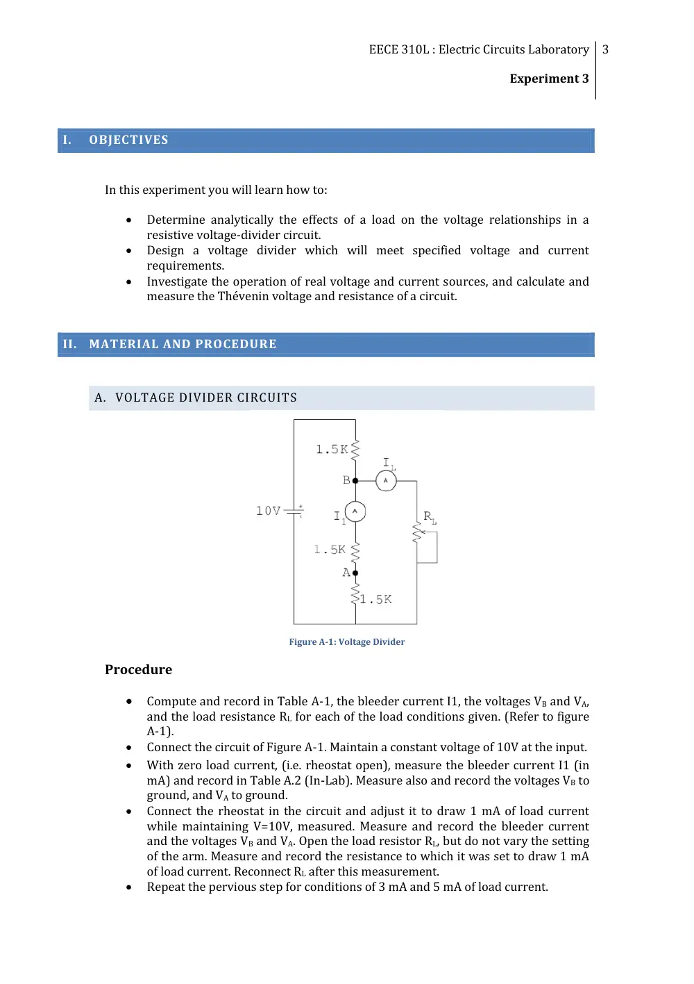
Figure A-1: Voltage Divider
Procedure
Compute and record in Table A-1, the bleeder current I1, the voltages VB and VA,
and the load resistance RL for each of the load conditions given. (Refer to figure
A-1).
Connect the circuit of Figure A-1. Maintain a constant voltage of 10V at the input.
With zero load current, (i.e. rheostat open), measure the bleeder current I1 (in
mA) and record in Table A.2 (In-Lab). Measure also and record the voltages VB to
ground, and VA to ground.
Connect the rheostat in the circuit and adjust it to draw 1 mA of load current
while maintaining V=10V, measured. Measure and record the bleeder current
and the voltages VB and VA. Open the load resistor RL, but do not vary the setting
of the arm. Measure and record the resistance to which it was set to draw 1 mA
of load current. Reconnect RL after this measurement.
Repeat the pervious step for conditions of 3 mA and 5 mA of load current.
EECE 310L : Electric Circuits Laboratory
Experiment 3
4
B. VOLTAGE DIVIDER DESIGN
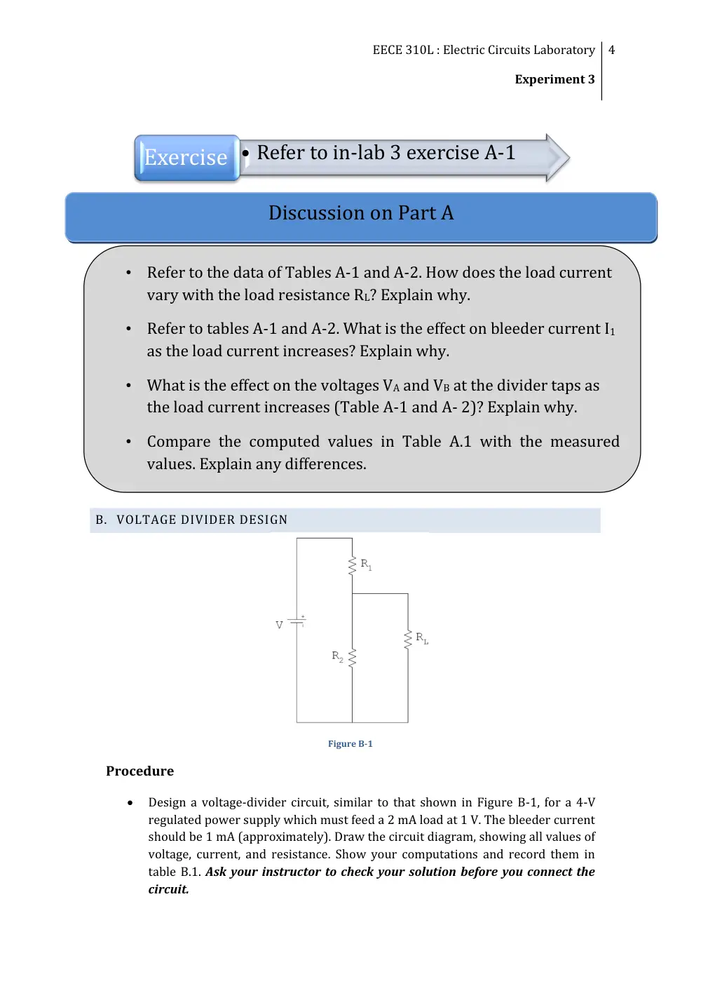
Figure B-1
Procedure
Design a voltage-divider circuit, similar to that shown in Figure B-1, for a 4-V
regulated power supply which must feed a 2 mA load at 1 V. The bleeder current
should be 1 mA (approximately). Draw the circuit diagram, showing all values of
voltage, current, and resistance. Show your computations and record them in
table B.1. Ask your instructor to check your solution before you connect the
circuit.
• Refer to in-lab 3 exercise A-1
Exercise
Discussion on Part A
• Refer to the data of Tables A-1 and A-2. How does the load current
vary with the load resistance RL? Explain why.
• Refer to tables A-1 and A-2. What is the effect on bleeder current I1
as the load current increases? Explain why.
• What is the effect on the voltages VA and VB at the divider taps as
the load current increases (Table A-1 and A- 2)? Explain why.
• Compare the computed values in Table A.1 with the measured
values. Explain any differences.
EECE 310L : Electric Circuits Laboratory
Experiment 3
5
Select the required resistors from your kit. If your kit does not contain a design-
value resistor, adjust a potentiometer connected as a rheostat to the desired
value, or make up the resistor from a combination (series, parallel) of the other
resistors.
Connect the circuit. Measure the required voltages and currents and record them
in a table B.2 (In lab).
C. THÉVENIN’S THEOREM
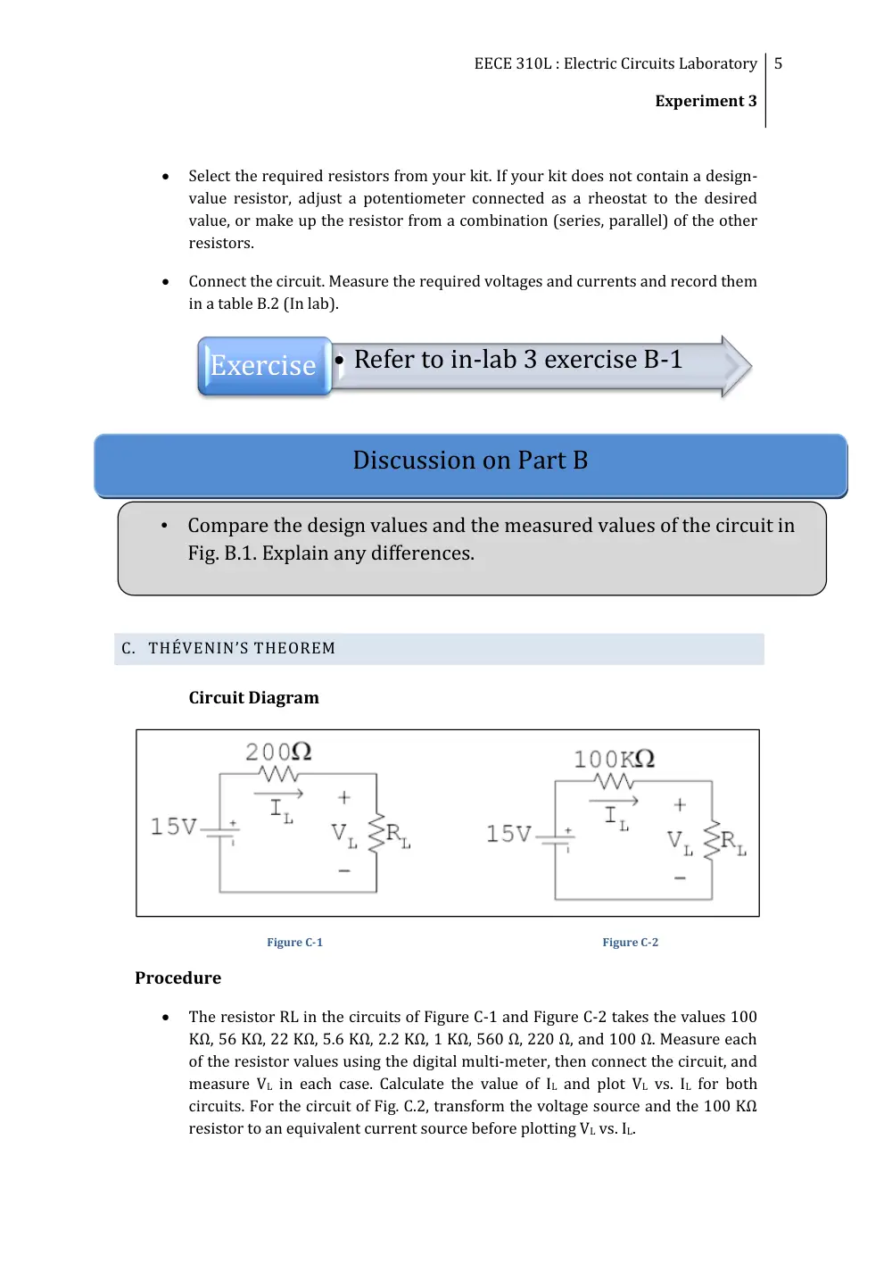
Circuit Diagram
Figure C-1
Figure C-2
Procedure
The resistor RL in the circuits of Figure C-1 and Figure C-2 takes the values 100
KΩ, 56 KΩ, 22 KΩ, 5.6 KΩ, 2.2 KΩ, 1 KΩ, 560 Ω, 220 Ω, and 100 Ω. Measure each
of the resistor values using the digital multi-meter, then connect the circuit, and
measure VL in each case. Calculate the value of IL and plot VL vs. IL for both
circuits. For the circuit of Fig. C.2, transform the voltage source and the 100 KΩ
resistor to an equivalent current source before plotting VL vs. IL.
• Refer to in-lab 3 exercise B-1
Exercise
Discussion on Part B
• Compare the design values and the measured values of the circuit in
Fig. B.1. Explain any differences.
EECE 310L : Electric Circuits Laboratory
Experiment 3
6
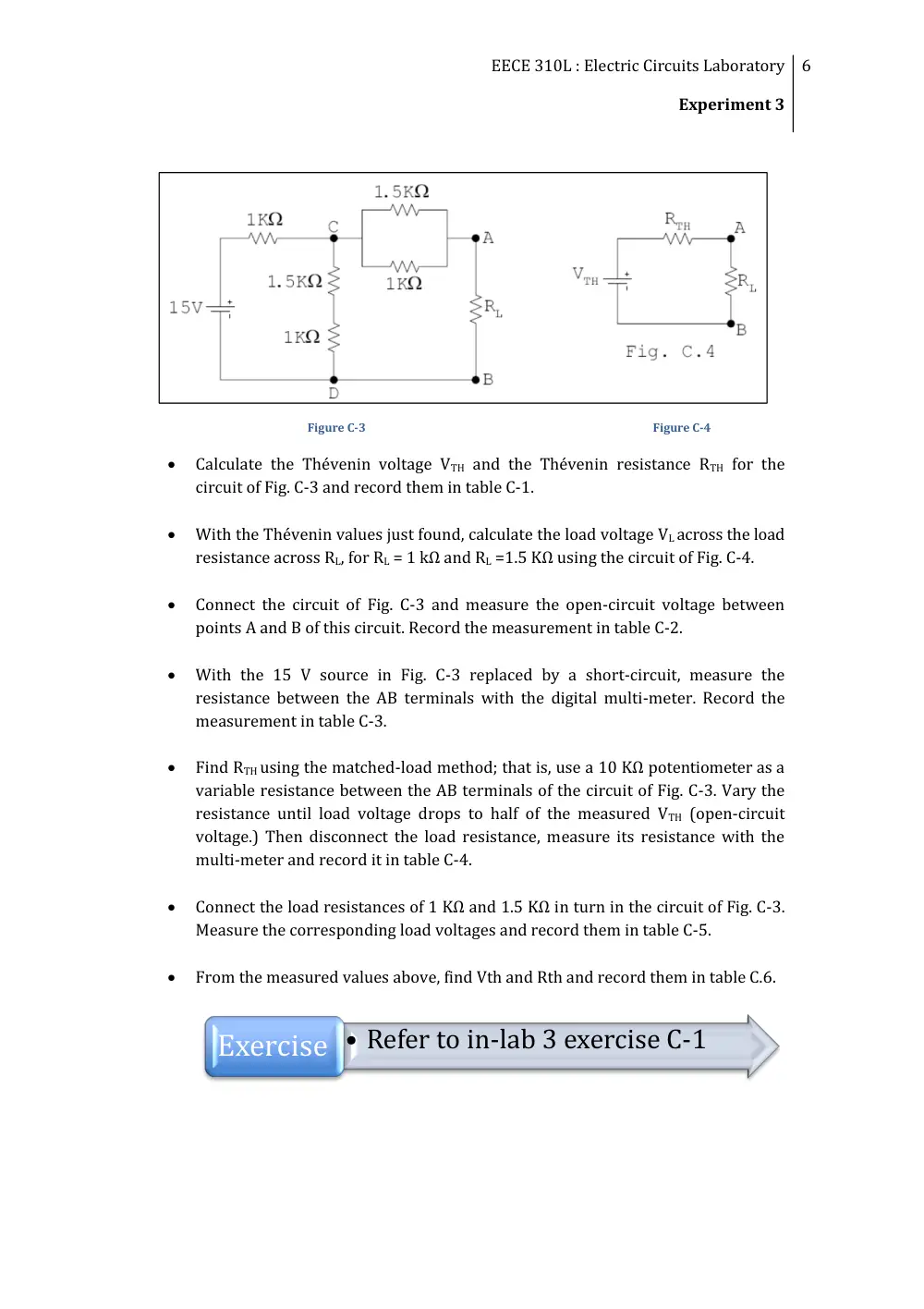
Figure C-3
Figure C-4
Calculate the Thévenin voltage VTH and the Thévenin resistance RTH for the
circuit of Fig. C-3 and record them in table C-1.
With the Thévenin values just found, calculate the load voltage VL across the load
resistance across RL, for RL = 1 kΩ and RL =1.5 KΩ using the circuit of Fig. C-4.
Connect the circuit of Fig. C-3 and measure the open-circuit voltage between
points A and B of this circuit. Record the measurement in table C-2.
With the 15 V source in Fig. C-3 replaced by a short-circuit, measure the
resistance between the AB terminals with the digital multi-meter. Record the
measurement in table C-3.
Find RTH using the matched-load method; that is, use a 10 KΩ potentiometer as a
variable resistance between the AB terminals of the circuit of Fig. C-3. Vary the
resistance until load voltage drops to half of the measured VTH (open-circuit
voltage.) Then disconnect the load resistance, measure its resistance with the
multi-meter and record it in table C-4.
Connect the load resistances of 1 KΩ and 1.5 KΩ in turn in the circuit of Fig. C-3.
Measure the corresponding load voltages and record them in table C-5.
From the measured values above, find Vth and Rth and record them in table C.6.
Exercise • Refer to in-lab 3 exercise C-1
EECE 310L : Electric Circuits Laboratory
Experiment 3
7
D. OUTCOMES
By the end of Experiment III, students:
Should understand the effect of a load on voltage relationship in a voltage
divider circuits.
Are able to design a voltage divider circuit that meet the specified voltage and
current requirements
Are familiar with the real operation of voltage and current sources
Are able to measure and calculate the Thévenin voltage and resistance using
multiple methods.
Discussion on Part C
• Over what range of values of RL can the source of Fig. C-1 be
considered to closely approximate an ideal voltage source?
• Over what range of values of RL can the source of Fig. C-2 be
considered to closely approximate an ideal current source?
• Convert the source in Fig. C.2 to an ideal current source in
parallel with a source resistance using Norton's theorem; prove
the equivalence by writing the circuit equations.
• Compare the measured and theoretical values obtained for VTH
and RTH of Fig. C-3. Explain any differences in the values of VTH
and RTH.
• With the 1 KΩ resistor in branch CD of Fig. C-3 opened;
calculate VTH and RTH of the modified circuit. Explain any
differences in the values of VTH and RTH.
• In the Procedure of Part C, RTH was derived by shorting the 15
V source in Fig. C-3 and measuring the resistance between A
and B. In the statement of Thévenin's theorem, RTH is derived
from the current that flows when RL is shorted. Verify the
equivalence of these two methods.