
EECE 310L Lab 5, Fall 2011
American University of Beirut · Electric Circuits Laboratory · 8 pages



More EECE 310L files
Show the text of this lab
EECE 310L : Electric Circuits Laboratory
Experiment 5
1
A m e r i c a n U n i v e r s i t y o f B e i r u t
Fall 2011
Experiment 5
Diode Rectifier Circuits
EECE 310L : Electric Circuits Laboratory
Experiment 5
2
Table of Contents
I.
Objectives .................................................................................................................................. 3
II.
Theory ......................................................................................................................................... 3
III. Material and Procedure ........................................................................................................ 4
A.
Rectifier Characteristics .................................................................................................. 4
B.
Full Wave Rectifier with Capacitor .............................................................................. 6
B1.
Full Wave Rectifier with Capacitor Calculations ....................................................... 6
B2.
Full Wave Rectifier with Capacitor Measurements .................................................. 6
IV. Outcomes ................................................................................................................................... 8
EECE 310L : Electric Circuits Laboratory
Experiment 5
3
I.
OBJECTIVES
In this experiment you will learn how to:
Measure and calculate all the characteristics of the half-wave rectifier.
Measure, calculate, and compare the characteristics of full-wave rectifiers.
Measure and calculate the characteristics of a rectifier with a capacitor filter.
Design a rectifier circuit with a capacitor filter by proper choice of the
transformer secondary voltage and the capacitance value.
II. THEORY
A rectifier circuit converts an alternating input to a unidirectional output. This may be
accomplished by using unidirectional devices, which allow the passage of current in one
direction through the device but not in the opposite direction. The most common types
of unidirectional devices are semiconductor diodes. Ideally, a diode behaves as a perfect
switch. In the forward direction it has a zero resistance and zero offset voltage. In the
reverse direction, it behaves as an open circuit.
Note The half-wave rectifier blocks the negative variations of the input; the output is
approximately equal to the input when the input is positive, and is zero otherwise. In the
full-wave rectifier, on the other hand, the output is approximately equal to the absolute
value of the input.
The most important characteristics which must be specified for a rectifier circuit are:
1. DC output voltage.
2. Ripple-factor, defined as a ratio of the peak-to-peak ripple (voltage variation in
the output) to the average voltage across the load.
3. Average and peak currents in each diode.
4. Peak inverse voltage (PIV) for each diode.
5. Percent regulation, defined as
, where V0 is the no-load voltage and VL is the
full-load voltage.
6. Transformer requirements, such as the secondary winding voltage and current
ratings.
It should be carefully noted that these characteristics, depend, in general, upon the type
of load connected to the rectifier output, i.e., whether it is resistive, capacitive or
inductive.
A transformer is used for stepping-down the input AC voltage. It is a device that
transmits AC power from one circuit to another through magnetic coupling, often with
no conductive connection. The transformation process obeys the relationships:
and
where subscripts 1 and 2 refer to the primary and secondary sides,
respectively.
EECE 310L : Electric Circuits Laboratory
Experiment 5
4
A capacitor can be connected at the output of the rectifier to smooth the voltage
variations. An approximate analysis for a full-wave rectifier with a capacitor filter gives
the following:
PEAK-TO-PEAK RIPPLE VOLTAGE:
DC VOLTAGE:
DC CURRENT:
where is the peak AC input voltage (at the secondary of the transformer), RL is the
load resistance, C is the filter capacitance, and f is the frequency of the AC voltage.
III. MATERIAL AND PROCEDURE
A. RECTIFIER CHARACTERISTICS
Procedure
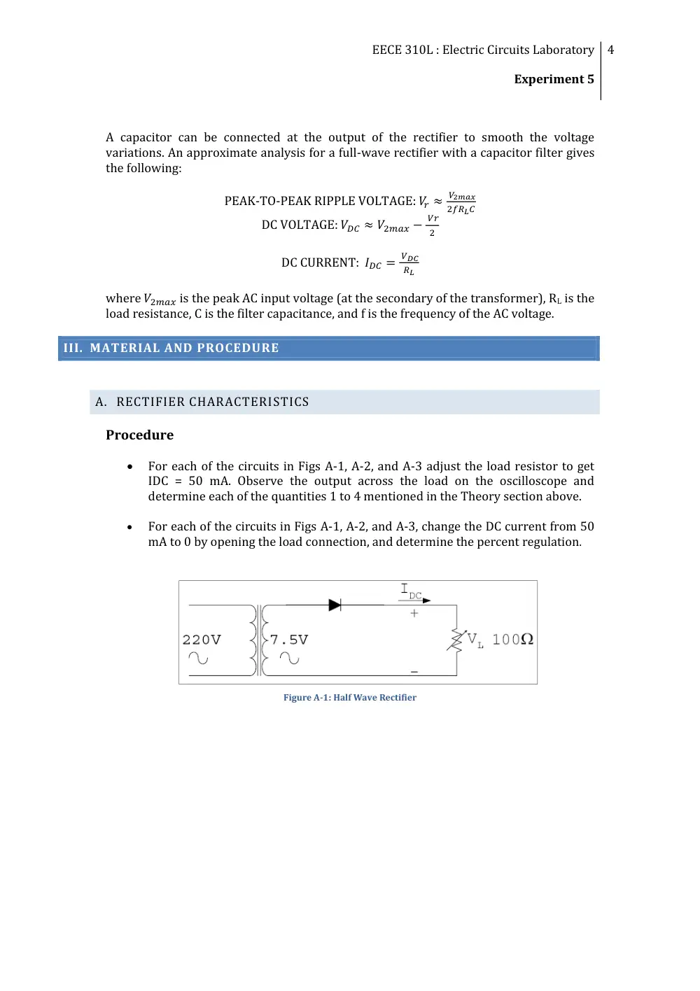
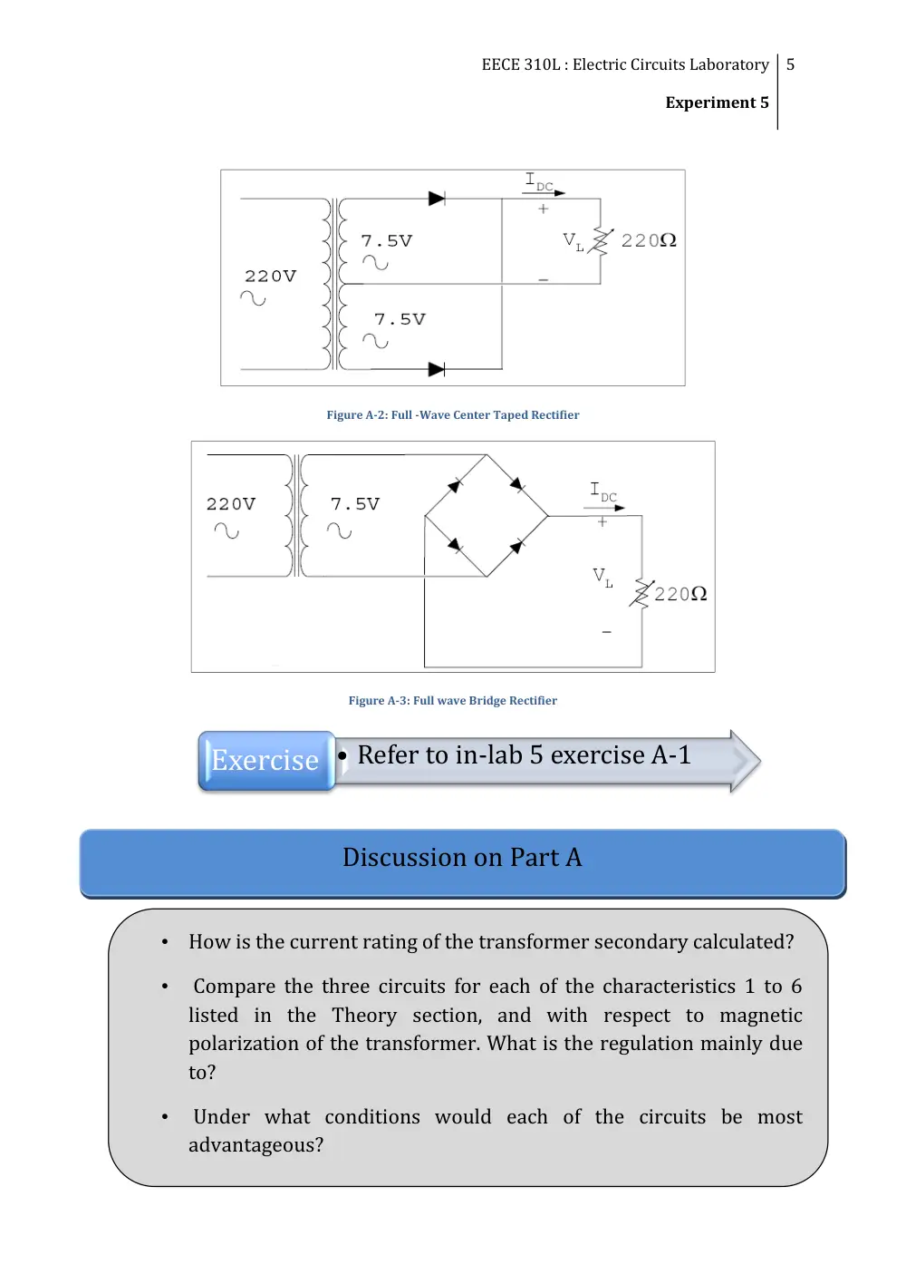
For each of the circuits in Figs A-1, A-2, and A-3 adjust the load resistor to get
IDC = 50 mA. Observe the output across the load on the oscilloscope and
determine each of the quantities 1 to 4 mentioned in the Theory section above.
For each of the circuits in Figs A-1, A-2, and A-3, change the DC current from 50
mA to 0 by opening the load connection, and determine the percent regulation.
Figure A-1: Half Wave Rectifier
EECE 310L : Electric Circuits Laboratory
Experiment 5
5
Discussion on Part A
•
How is the current rating of the transformer secondary calculated?
•
Compare the three circuits for each of the characteristics 1 to 6
listed in the Theory section, and with respect to magnetic
polarization of the transformer. What is the regulation mainly due
to?
•
Under what conditions would each of the circuits be most
advantageous?
Figure A-2: Full -Wave Center Taped Rectifier
Figure A-3: Full wave Bridge Rectifier
Exercise • Refer to in-lab 5 exercise A-1
EECE 310L : Electric Circuits Laboratory
Experiment 5
6
B. FULL WAVE RECTIFIER WITH CAPACITOR
B1. FULL WAVE RECTIFIER WITH CAPACITOR CALCULATIONS
Calculate the values of Vr and VDC using the approximate relations in the Theory section,
with RL = 680 Ω and the following values of the capacitor: 1, 22, 100, and 1000 µF.
Repeat for RL = 2.2 KΩ. Record your data in Table B.1.
B2. FULL WAVE RECTIFIER WITH CAPACITOR MEASUREMENTS
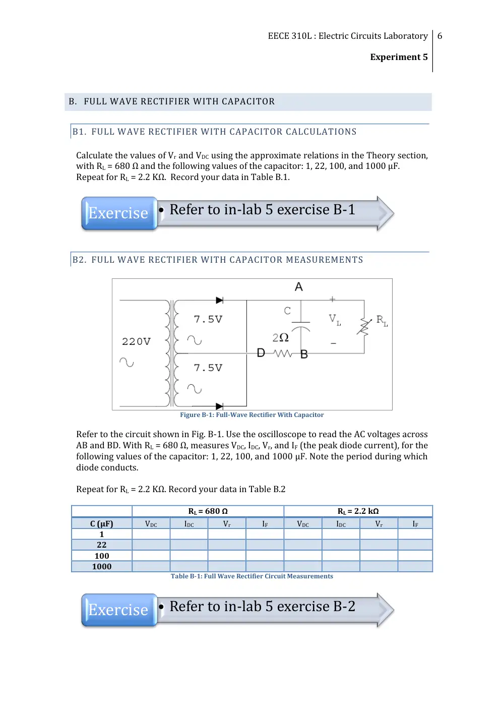
Figure B-1: Full-Wave Rectifier With Capacitor
Refer to the circuit shown in Fig. B-1. Use the oscilloscope to read the AC voltages across
AB and BD. With RL = 680 Ω, measures VDC, IDC, Vr, and IF (the peak diode current), for the
following values of the capacitor: 1, 22, 100, and 1000 µF. Note the period during which
diode conducts.
Repeat for RL = 2.2 KΩ. Record your data in Table B.2
RL = 680 Ω
RL = 2.2 kΩ
C (µF)
VDC
IDC
Vr
IF
VDC
IDC
Vr
IF
1
22
100
1000
Table B-1: Full Wave Rectifier Circuit Measurements
• Refer to in-lab 5 exercise B-1
Exercise
• Refer to in-lab 5 exercise B-2
Exercise
EECE 310L : Electric Circuits Laboratory
Experiment 5
7
Plot the following as a function of 10 log(2πf C RL):
i)
VDC / V2max
ii)
Vr / VDC
iii)
IF / IDC
Compare the measured values of Vr and VDC with those calculated using the approximate
relations in the Theory section above.
Discussion on Part B
•
Does VDC increase appreciably with C for all values of C?
•
Does Vr decrease appreciably with C for the values of C used in
the experiment?
•
Does the ratio IF/IDC vary with C? Of what practical
importance is this ratio?
•
Under what conditions are the approximate relations in the
Theory section adequate for calculating Vr and VDC?
•
How does the presence of the capacitor affect the regulation of
the circuit?
•
What additional current rating of diodes must be considered
for the capacitor filter?
•
For a certain required ripple voltage and DC voltage/current at
the load:
•
What should be the RMS voltage rating of the secondary
of the transformer?
•
What should be the value of the capacitor?
EECE 310L : Electric Circuits Laboratory
Experiment 5
8
IV. OUTCOMES
By the end of Experiment V, students:
Are able to measure and calculate all the characteristics of half wave Rectifier,
Full wave Rectifier, and Rectifiers with filters.
Should understand the different characteristics of rectifiers’ circuits and their
importance.
Are able to design a rectifier circuit with capacitor filter.