
EECE 310L Lab Report, Fall 2003
American University of Beirut · Electric Circuits Laboratory · 2 pages
More EECE 310L files
Show the text of this lab
Experiment 3: Voltage Dividers and Thevénin's Theorem
Experiment 3:
Voltage Dividers and Thevénin's Theorem
In-Lab Report
A. Voltage divider circuits
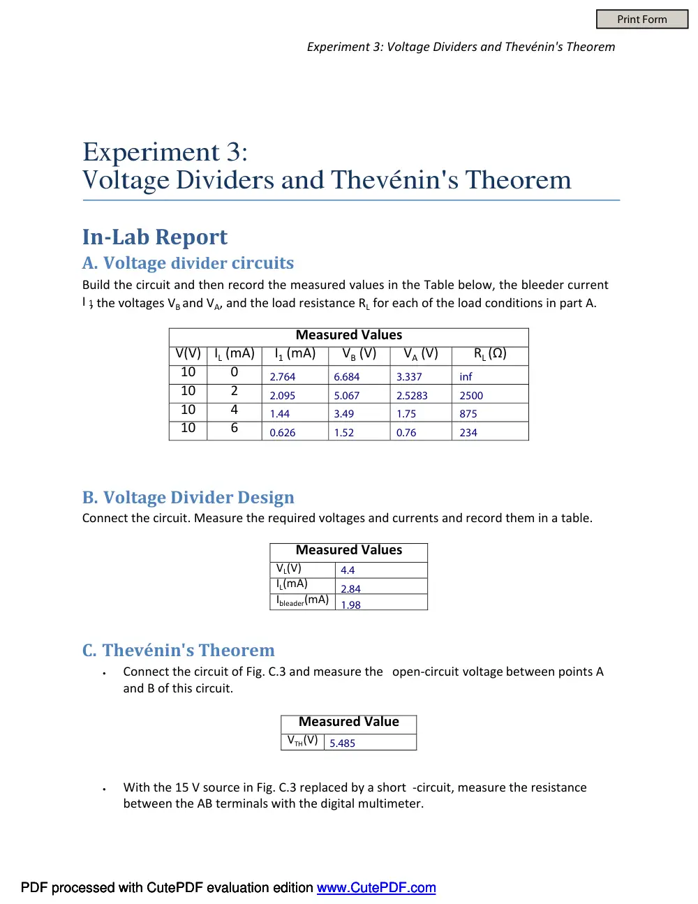
Build the circuit and then record the measured values in the Table below, the bleeder current
I 1, the voltages VBand VA, and the load resistance RL for each of the load conditions in part A.
Measured Values
V(V)
IL (mA)
I1 (mA)
VB (V)
VA (V)
RL (Ω)
10
0
10
2
10
4
10
6
B. Voltage Divider Design
Connect the circuit. Measure the required voltages and currents and record them in a table.
Measured Values
VL(V)
IL(mA)
Ibleader(mA)
C. Thevénin's Theorem
•
Connect the circuit of Fig. C.3 and measure the open-circuit voltage between points A
and B of this circuit.
Measured Value
VTH(V)
•
With the 15 V source in Fig. C.3 replaced by a short -circuit, measure the resistance
between the AB terminals with the digital multimeter.
PDF processed with CutePDF evaluation edition www.CutePDF.com
PDF processed with CutePDF evaluation edition www.CutePDF.com
PDF processed with CutePDF evaluation edition www.CutePDF.com
Print Form
2.764
6.684
3.337
inf
2.095
5.067
2.5283
2500
1.44
3.49
1.75
875
0.626
1.52
0.76
234
4.4
2.84
1.98
5.485
Experiment 3: Voltage Dividers and Thevénin's Theorem
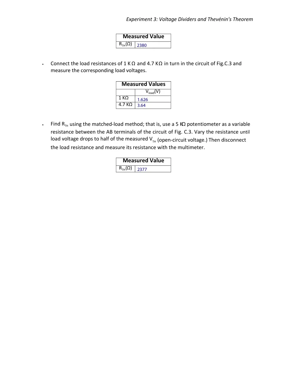
Measured Value
RTH(Ω)
•
Connect the load resistances of 1 K Ω and 4.7 KΩ in turn in the circuit of Fig.C.3 and
measure the corresponding load voltages.
Measured Values
Vload(V)
1 KΩ
4.7 KΩ
•
Find RTH using the matched-load method; that is, use a 5 KΩ potentiometer as a variable
resistance between the AB terminals of the circuit of Fig. C.3. Vary the resistance until
load voltage drops to half of the measured VTH (open-circuit voltage.) Then disconnect
the load resistance and measure its resistance with the multimeter.
Measured Value
RTH(Ω)
2380
1.626
3.64
2377