
EECE 320 Problems, Fall 2010
American University of Beirut · Digital Systems Design · 63 pages

Showing the first 10 of 63 pages. Download the PDF to see all of it.
More EECE 320 files
- Problems Recitations Solutions · Fall 2011Problems · with solutionView
- Problems Important Problems on Memory, Flip Flops · Fall 2010ProblemsView
- Homework 2 · Fall 2016HomeworkView
- Homework 4 · Summer 2016HomeworkView
- Homework 2 and 3 · Summer 2016HomeworkView
- Homework 1 · Summer 2016HomeworkView
- Homework 1 · Fall 2016HomeworkView
- Homework 3 · Fall 2016HomeworkView
Show the text of this problems
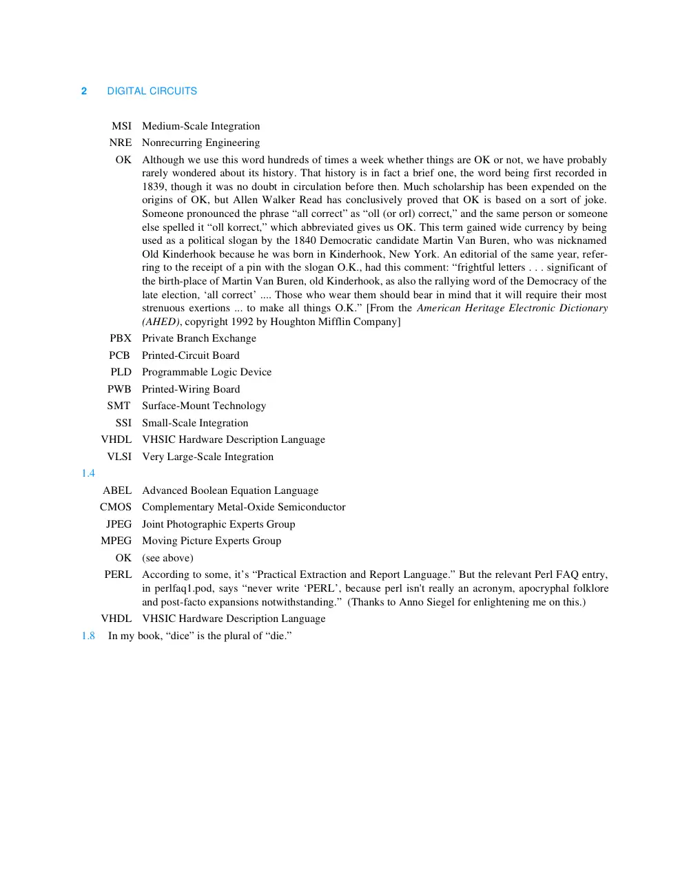
1–1
E X E R C I S E S O L U T I O N S
INTRODUCTION
1
1.2
Three definitions of “bit”:
(1) A binary digit (p. 1).
(2) Past tense of “bite” (p. 1).
(3) A small amount (pp. 6, 10).
1.3
ASIC Application-Specific Integrated Circuit
CAD
Computer-Aided Design
CD
Compact Disc
CO Central Office
CPLD
Complex Programmable Logic Device
DAT
Digital Audio Tape
DIP Dual In-line Pin
DVD
Digital Versatile Disc
FPGA
Field-Programmable Gate Array
HDL
Hardware Description Language
IC Integrated Circuit
IP
Internet Protocol
LSI Large-Scale Integration
MCM
Multichip Module
2
DIGITAL CIRCUITS
MSI Medium-Scale Integration
NRE Nonrecurring Engineering
OK Although we use this word hundreds of times a week whether things are OK or not, we have probably
rarely wondered about its history. That history is in fact a brief one, the word being first recorded in
1839, though it was no doubt in circulation before then. Much scholarship has been expended on the
origins of OK, but Allen Walker Read has conclusively proved that OK is based on a sort of joke.
Someone pronounced the phrase “all correct” as “oll (or orl) correct,” and the same person or someone
else spelled it “oll korrect,” which abbreviated gives us OK. This term gained wide currency by being
used as a political slogan by the 1840 Democratic candidate Martin Van Buren, who was nicknamed
Old Kinderhook because he was born in Kinderhook, New York. An editorial of the same year, refer-
ring to the receipt of a pin with the slogan O.K., had this comment: “frightful letters . . . significant of
the birth-place of Martin Van Buren, old Kinderhook, as also the rallying word of the Democracy of the
late election, ‘all correct’ .... Those who wear them should bear in mind that it will require their most
strenuous exertions ... to make all things O.K.” [From the American Heritage Electronic Dictionary
(AHED), copyright 1992 by Houghton Mifflin Company]
PBX
Private Branch Exchange
PCB Printed-Circuit Board
PLD Programmable Logic Device
PWB Printed-Wiring Board
SMT Surface-Mount Technology
SSI Small-Scale Integration
VHDL
VHSIC Hardware Description Language
VLSI Very Large-Scale Integration
1.4
ABEL
Advanced Boolean Equation Language
CMOS
Complementary Metal-Oxide Semiconductor
JPEG
Joint Photographic Experts Group
MPEG
Moving Picture Experts Group
OK
(see above)
PERL
According to some, it’s “Practical Extraction and Report Language.” But the relevant Perl FAQ entry,
in perlfaq1.pod, says “never write ‘PERL’, because perl isn't really an acronym, apocryphal folklore
and post-facto expansions notwithstanding.” (Thanks to Anno Siegel for enlightening me on this.)
VHDL
VHSIC Hardware Description Language
1.8
In my book, “dice” is the plural of “die.”
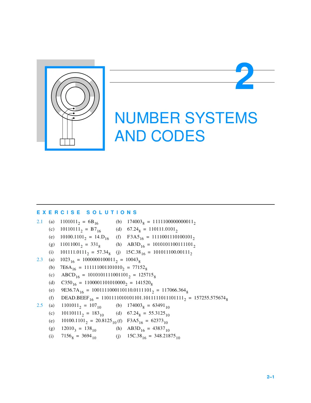
2–1
E X E R C I S E S O L U T I O N S
NUMBER SYSTEMS
AND CODES
2
2.1
(a)
(b)
(c)
(d)
(e)
(f)
(g)
(h)
(i)
(j)
2.3
(a)
(b)
(c)
(d)
(e)
(f)
2.5
(a)
(b)
(c)
(d)
(e)
(f)
(g)
(h)
(i)
(j)
11010112
= 6B16
1740038
11111000000000112
=
101101112
= B716
67.248
110111.01012
=
10100.11012
= 14.D16
F3A516
11110011101001012
=
110110012
= 3318
AB3D16
10101011001111012
=
101111.01112
= 57.348
15C.3816
101011100.001112
=
102316
10000001000112
100438
=
=
7E6A16
1111110011010102
771528
=
=
ABCD16
10101011110011012
1257158
=
=
C35016
11000011010100002
1415208
=
=
9E36.7A16
1001111000110110.01111012
117066.3648
=
=
DEAD.BEEF16
1101111010101101.10111110111011112
157255.5756748
=
=
11010112
= 10710
1740038
6349110
=
101101112
= 18310
67.248
55.312510
=
10100.11012
= 20.812510
F3A516
6237310
=
120103
= 13810
AB3D16
4383710
=
71568
= 369410
15C.3816
= 348.2187510
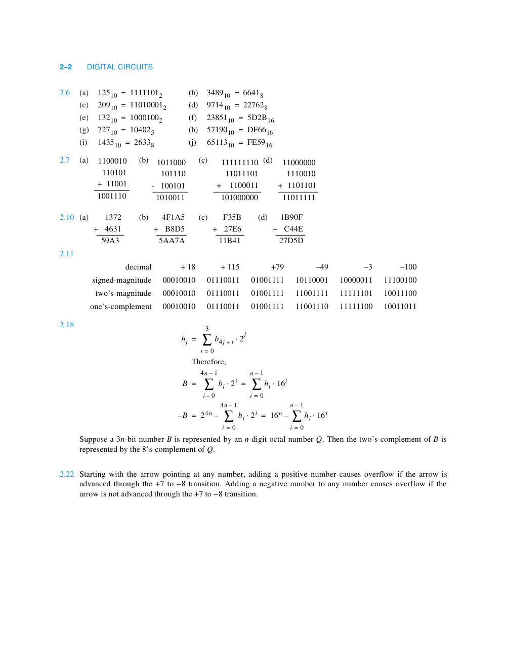
2–2
DIGITAL CIRCUITS
2.6
(a)
(b)
(c)
(d)
(e)
(f)
(g)
(h)
(i)
(j)
2.7
(a)
(b)
(c)
(d)
2.10 (a)
(b)
(c)
(d)
2.11
2.18
Suppose a 3n-bit number B is represented by an n-digit octal number Q. Then the two’s-complement of B is
represented by the 8’s-complement of Q.
2.22 Starting with the arrow pointing at any number, adding a positive number causes overflow if the arrow is
advanced through the +7 to –8 transition. Adding a negative number to any number causes overflow if the
arrow is not advanced through the +7 to –8 transition.
12510
= 11111012
348910
66418
=
20910
= 110100012
971410
227628
=
13210
= 10001002
2385110
5D2B16
=
72710
= 104025
5719010
DF6616
=
143510
= 26338
6511310
FE5916
=
1100010
110101
+ 11001
1001110
--------------------------
1011000
101110
+
100101
1010011
--------------------------
111111110
11011101
+ 1100011
101000000
-----------------------------------
11000000
1110010
+ 1101101
11011111
-----------------------------
1372
+
4631
59A3
--------------------
4F1A5
+
B8D5
5AA7A
----------------------
F35B
+
27E6
11B41
---------------------
1B90F
+
C44E
27D5D
----------------------
decimal
+ 18
+ 115
+79
–49
–3
–100
signed-magnitude
00010010
01110011
01001111
10110001
10000011
11100100
two’s-magnitude
00010010
01110011
01001111
11001111
11111101
10011100
one’s-complement
00010010
01110011
01001111
11001110
11111100
10011011
hj
b4j
+ i
2j
⋅
i
0
=
3
∑
=
Therefore,
B
bi 2i
⋅
i
0
–
4n
– 1
∑
hi 16i
⋅
i
0
=
n
– 1
∑
=
=
–B
24n
bi
i
0
=
4n
– 1
∑
⋅ 2i
–
16n
hi 16i
⋅
i
0
=
n
– 1
– ∑
=
=
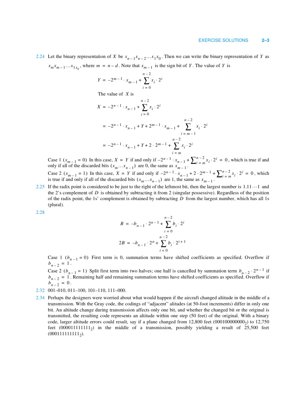
EXERCISE SOLUTIONS
2–3
2.24 Let the binary representation of
be
. Then we can write the binary representation of
as
, where
. Note that
is the sign bit of
. The value of
is
Case 1
In this case,
if and only if
, which is true if and
only if all of the discarded bits
are 0, the same as
.
Case 2
In this case,
if and only if
, which
is true if and only if all of the discarded bits
are 1, the same as
.
2.25 If the radix point is considered to be just to the right of the leftmost bit, then the largest number is
and
the 2’s complement of
is obtained by subtracting it from 2 (singular possessive). Regardless of the position
of the radix point, the 1s’ complement is obtained by subtracting
from the largest number, which has all 1s
(plural).
2.28
Case 1
First term is 0, summation terms have shifted coefficients as specified. Overflow if
.
Case 2
Split first term into two halves; one half is cancelled by summation term
if
. Remaining half and remaining summation terms have shifted coefficients as specified. Overflow if
.
2.32 001–010, 011–100, 101–110, 111–000.
2.34 Perhaps the designers were worried about what would happen if the aircraft changed altitude in the middle of a
transmission. With the Gray code, the codings of “adjacent” alitudes (at 50-foot increments) differ in only one
bit. An altitude change during transmission affects only one bit, and whether the changed bit or the original is
transmitted, the resulting code represents an altitude within one step (50 feet) of the original. With a binary
code, larger altitude errors could result, say if a plane changed from 12,800 feet (0001000000002) to 12,750
feet (0000111111112) in the middle of a transmission, possibly yielding a result of 25,500 feet
(0001111111112).
X
xn
1
– xn
2
– …x1x0
Y
xmxm
1
– …x1x0
m
n
– d
=
xm
– 1
Y
Y
Y
2m
– 1
–
xm
– 1
xi 2i
⋅
i
0
=
n
– 2
+ ∑
⋅
=
The value of X is
X
2n
– 1
–
xn
– 1
xi 2i
⋅
i
0
=
n
– 2
+ ∑
⋅
=
2n
– 1
–
xn
– 1
Y
2m
– 1
xm
– 1
⋅
xi 2i
⋅
i
m
– 1
=
n
– 2
∑
+
+
+
⋅
=
2n
– 1
–
xn
– 1
Y
2 2m
– 1
⋅
xi 2i
⋅
i
m
=
n
– 2
∑
+
+
+
⋅
=
xm
– 1
= 0
(
)
X
= Y
2n
– 1
–
xn
– 1
⋅
xi 2i
⋅
i
= m
n
– 2
+ ∑
= 0
xm…xn
– 1
(
)
xm
– 1
xm
– 1
= 1
(
)
X
= Y
2n
– 1
–
xn
– 1
⋅
2 2m
– 1
⋅
xi 2i
⋅
i
= m
n
– 2
∑
+
+
= 0
xm…xn
– 1
(
)
xm
– 1
1.11…1
D
D
B
bn
– 1
–
2n
– 1
⋅
bi 2i
⋅
i
0
=
n
– 2
+ ∑
=
2B
bn
– 1
–
2n
bi 2i
+ 1
⋅
i
0
=
n
– 2
+ ∑
⋅
=
bn
– 1
= 0
(
)
bn
– 2
1
=
bn
– 1
= 1
(
)
bn
– 2
2n
– 1
⋅
bn
– 2
= 1
bn
– 2
= 0
2–4
DIGITAL CIRCUITS
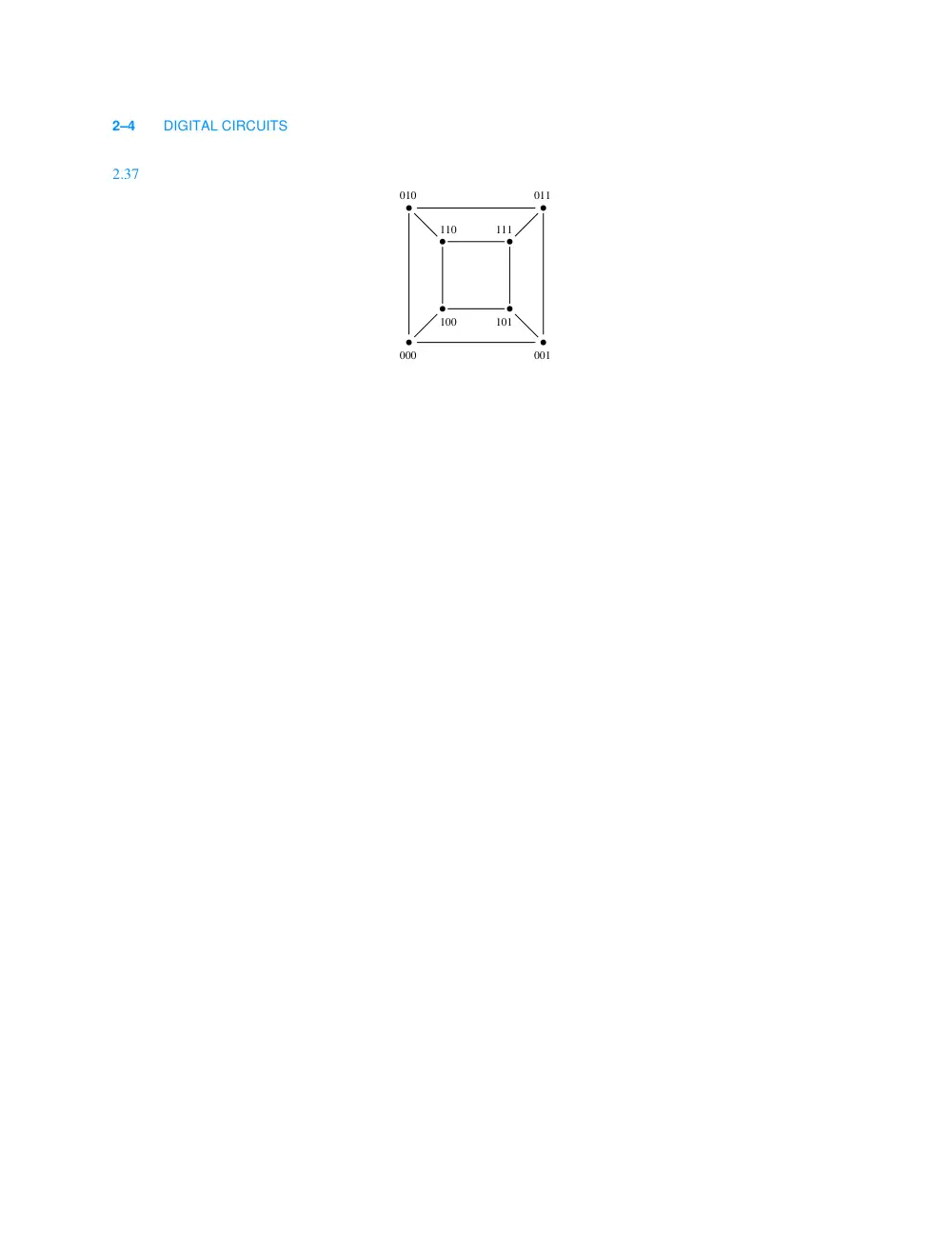
2.37
010
011
000
001
111
110
100
101
3–1
E X E R C I S E S O L U T I O N S
DIGITAL CIRCUITS
3
3.1
The “probably” cases may cause damage to the gate if sustained.
3.3
A logic buffer is a non-linear amplifier that maps the entire set of possible analog input voltages into just two
output votages, HIGH and LOW. An audio amplifier has a linear response over its specified operating range,
mapping each input voltage into an output voltage that is directly proprtional to the input voltage.
3.6
From the American Heritage Electronic Dictionary (AHED), copyright 1992 by Houghton Mifflin Company:
(1)
A structure that can be swung, drawn, or lowered to block an entrance or a passageway.
(2)
a. An opening in a wall or fence for entrance or exit. b. The structure surrounding such an opening, such as
the monumental or fortified entrance to a palace or walled city.
(3)
a. A means of access: the gate to riches. b. A passageway, as in an airport terminal, through which passen-
gers proceed for embarkation.
(4)
A mountain pass.
(5)
The total paid attendance or admission receipts at a public event: a good gate at the football game.
(6)
A device for controlling the passage of water or gas through a dam or conduit.
(7)
The channel through which molten metal flows into a shaped cavity of a mold.
(8)
Sports. A passage between two upright poles through which a skier must go in a slalom race.
(9)
Electronics. A circuit with multiple inputs and one output that is energized only when a designated set of
input pulses is received.
(a) 0
(b) 1
(c) 0
(d) undefined
(e) 1
(f) probably 1
(g) probably 0
(h) probably 0
3–2
DIGITAL CIRCUITS
Well, definition (9) is closest to one of the answers that I had in mind. The other answer I was looking for is the
gate of a MOS transistor.
3.14 A CMOS inverting gate has fewer transistors than a noninverting one, since an inversion comes “for free.”
3.15 Simple, inverting CMOS gates generally have two transistors per input. Four examples that meet the require-
ments of the problem are 4-input NAND , 4-input NOR , 2-in, 2-wide AND–OR–INVERT , and 2-in, 2-wide OR–
AND–INVERT.
3.18 One way is that a romance could be sparked, and the designers could end up with a lot less time to do their
work. Another way is that the stray perfume in the IC production line could have contaminated the circuits used
by the designers, leading to marginal operation, more debugging time by the deidicated designers, and less time
for romance. By the way, the whole perfume story may be apocryphal.
3.20 Using the maximum output current ratings in both states, the HIGH-state margin is 0.69V and the LOW-state
margin is 1.02V. With CMOS loads (output currents less than 20 µA), the margins improve to 1.349V and
1.25V, respectively.
3.21 The first answer for each parameter below assumes commercial operation and that the device is used with the
maximum allowable (TTL) load. The number in parentheses, if any, indicates the value obtained under a lesser
but specified (CMOS) load.
VOHmin
3.84V (4.4V )
VIHmin
3.15V
VILmax
1.35V
VOLmax
0.33V (0.1V)
IImax
1µA
IOLmax
4 mA (20 µA)
IOHmax
-4 mA (-20 µA)
3.22 Current is positive if it flows into a node. Therefore, an output with negative current is sourcing current.
3.23 The 74HC00 output drive is so weak, it’s not good for driving much:
(a)
Assume that in the LOW state the output pulls down to 0.33V (the maximum
spec). Then the output
current is
, which is way more than the 4-mA commercial spec.
(b)
For this problem, you first have to find the Thévenin equivalent of the load, or
in series with
. In the HIGH state, the gate must pull the output up to 3.84V, a difference of 1.59V across
,
requiring 10.7 mA, which is out of spec. In the LOW state, we have a voltage drop of
across
, so the output must sink 12.9 mA, again out of spec.
3.24 (In the first printing, change “74FCT257T” to “74HC00.”) The specification for the 74HC00 shows a maxi-
mum power-supply current of 10 µA when the inputs aree at 0 or 5V, but based on the discussion in
Section 3.5.3 we would expect the current to be more when the inputs are at their worst-case values (1.35 or
3.15V). If we consider “nonlogic” input values, the maximum current will flow if the inputs are held right at
the switching threshold, approximately VCC/2.
3.26 (In the first printing, change “74FCT257T” to “74HC00.”) Using the formulas on page 119, we can estimate
that
or, using the higher value of
in the spec, that
. (The discrepancy shows that the output characteristic of this device
is somewhat nonlinear.) We can also estimate
.
3.29 The purpose of decoupling capacitors is to provide the instantaneous power-supply current that is required dur-
ing output transitions. Printed-circuit board traces have inductance, which acts as a barrier to current flow at
high frequencies (fast transition rates). The farther the capacitor is from the device that needs decoupling, the
larger is the instantaneous voltage drop across the connecting signal path, resulting in larger spike (up or down)
in the device’s power-supply voltage.
VOL
(5.0V
) 120Ω
⁄
41.7mA
=
148.5Ω
2.25V
148.5Ω
2.25V
0.33V
–
148.5Ω
Rp(on)
5.0
– 3.84
(
) 0.004
⁄
290Ω
=
=
VOHmin
Rp(on)
5.0
– 4.4
(
) 0.00002
⁄
30KΩ
=
=
Rn(on)
0.33 0.004
⁄
82.5Ω
=
=
EXERCISE SOLUTIONS
3–3
3.32 (a) 5 ns.
3.38 Smaller resistors result in shorter rise times for LOW-to-HIGH transitions but higher power consumption in the
LOW state. Stated another way, larger resistors result in lower power consumption in the LOW state but longer
rise times (more ooze) for LOW -to-HIGH transitions.
3.39 The resistor must drop
with 5mA of current through it. Therefore
; a good standard value would be
.
3.41 (The Secret of the Ooze.) The wired output has only passive pull-up to the HIGH state. Therefore, the time for
LOW-to-HIGH transitions, an important component of total delay, depends on the amount of capacitive loading
and the size of the pull-up resistor. A moderate capacitive load (say, 100 pF) and even a very strong pull-up
resistor (say,
) can still lead to time constants and transition times (15 ns in this example) that are longer
than the delay of an additional gate with active pull-up.
3.42 The winner is 74FCT-T—48 mA in the LOW state and 15 mA in the HIGH state (see Table 3–8). TTL families
don’t come close.
3.46 n diodes are required.
3.49 For each interfacing situation, we compute the fanout in the LOW state by dividing
of the driving gate
by
of the driven gate. Similarly, the fanout in the HIGH state is computed by dividing
of the
driving gate by
of the driven gate. The overall fanout is the lower of these two results.
3.50 For the pull-down, we must have at most a 0.5-V drop in order to create a
that is no worse than a standard
LS-TTL output driving the input. Since
, we get
and
. (Alternatively,
)
For the pull-up, we must have at most a 2.3-V drop in order to create a
that is no worse than a standard
LS-TTL output driving the input. Since
, we get
and
. (Alternatively, we could have calculated the result as
.) The pull-up dissipates less power.
3.52 The main benefit of Schottky diodes is to prevent transistors from saturating, which allows them to switch more
quickly. The main drawback is that they raise the collector-to-emitter drop across an almost-saturated transis-
tor, which decreases LOW -state noise margin.
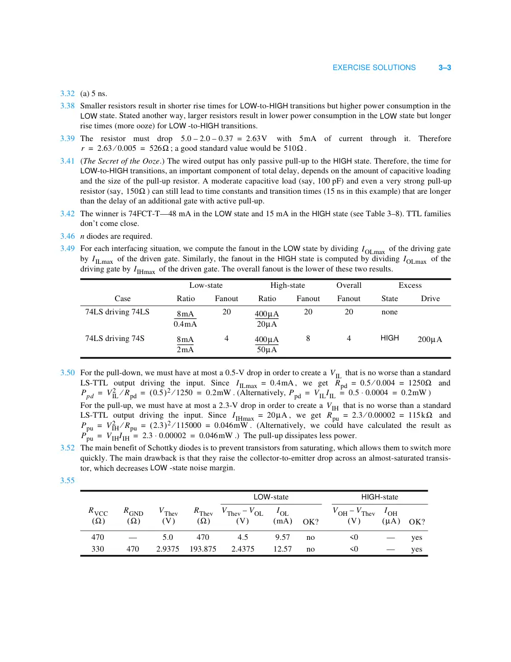
3.55
Low-state
High-state
Overall
Excess
Case
Ratio
Fanout
Ratio
Fanout
Fanout
State
Drive
74LS driving 74LS
20
20
20
none
74LS driving 74S
4
8
4
HIGH
LOW-state
HIGH-state
OK?
OK?
470
—
5.0
470
4.5
9.57
no
<0
—
yes
330
470
2.9375
193.875
2.4375
12.57
no
<0
—
yes
5.0
– 2.0
– 0.37
= 2.63V
r
2.63 0.005
⁄
526Ω
=
=
510Ω
150Ω
IOLmax
IILmax
IOLmax
IIHmax
8mA
0.4mA
----------------
400µA
20µA
-----------------
8mA
2mA
------------
400µA
50µA
-----------------
200µA
VIL
IILmax
= 0.4mA
Rpd
0.5 0.004
⁄
1250Ω
=
=
Ppd
VIL
2
⁄ Rpd
(0.5
)2 1250
⁄
0.2mW
=
=
=
Ppd
VILIIL
0.5 0.0004
⋅
0.2mW
=
=
=
VIH
IIHmax
= 20µA
Rpu
2.3 0.00002
⁄
115kΩ
=
=
Ppu
VIH
2
⁄ Rpu
(2.3
)2 115000
⁄
0.046mW
=
=
=
Ppu
VIHIIH
2.3 0.00002
⋅
0.046mW
=
=
=
RVCC
(Ω
)
RGND
(Ω
)
VThev
(V
)
RThev
(Ω
)
VThev
VOL
(V
)
–
IOL
(mA
)
VOH
VThev
(V
)
–
IOH
(µA
)
3–4
DIGITAL CIRCUITS
3.56
3.57 For each interfacing situation, we compute the fanout in the LOW state by dividing
of the driving gate
by
of the driven gate. Similarly, the fanout in the HIGH state is computed by dividing
of the
driving gate by
of the driven gate. The overall fanout is the lower of these two results.
3.64 TTL-compatible inputs have
, and typical TTL outputs have
. CMOS output
levels are already high compared to these levels, so there’s no point in wasting silicon to make them any higher
by lowering the voltage drop in the HIGH state.
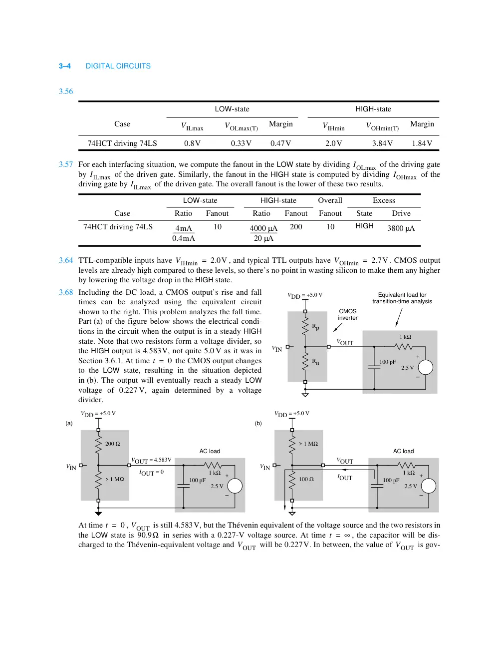
3.68 Including the DC load, a CMOS output’s rise and fall
times can be analyzed using the equivalent circuit
shown to the right. This problem analyzes the fall time.
Part (a) of the figure below shows the electrical condi-
tions in the circuit when the output is in a steady HIGH
state. Note that two resistors form a voltage divider, so
the HIGH output is 4.583V, not quite 5.0 V as it was in
Section 3.6.1. At time
the CMOS output changes
to the LOW state, resulting in the situation depicted
in (b). The output will eventually reach a steady LOW
voltage of 0.227 V, again determined by a voltage
divider.
At time
,
is still 4.583V, but the Thévenin equivalent of the voltage source and the two resistors in
the LOW state is
in series with a 0.227-V voltage source. At time
, the capacitor will be dis-
charged to the Thévenin-equivalent voltage and
will be 0.227V. In between, the value of
is gov-
LOW-state
HIGH-state
Case
Margin
Margin
74HCT driving 74LS
0.8V
0.33V
0.47V
2.0V
3.84V
1.84V
LOW-state
HIGH-state
Overall
Excess
Case
Ratio
Fanout
Ratio
Fanout
Fanout
State
Drive
74HCT driving 74LS
10
200
10
HIGH
VILmax
VOLmax(T)
VIHmin
VOHmin(T)
IOLmax
IILmax
IOHmax
IILmax
4mA
0.4mA
----------------
4000 µA
20 µA
--------------------
3800 µA
VIHmin
= 2.0V
VOHmin
2.7V
=
VDD = +5.0 V
VOUT
VIN
Rn
Rp
CMOS
inverter
Equivalent load for
transition-time analysis
+
–
2.5 V
1 kΩ
100 pF
t
0
=
AC load
+
–
2.5 V
1 kΩ
100 pF
VDD = +5.0 V
VOUT = 4.583V
IOUT = 0
IOUT
VIN
> 1 MΩ
200 Ω
AC load
VDD = +5.0 V
VOUT
VIN
(a)
(b)
100 Ω
> 1 MΩ
+
–
2.5 V
1 kΩ
100 pF
t
= 0
VOUT
90.9Ω
t
= ∞
VOUT
VOUT
EXERCISE SOLUTIONS
3–5
erned by an exponential law:
Because of the DC load resistance, the time constant is a little shorter than it was in Section 3.6.1, at 9.09 ns.
To obtain the fall time, we must solve the preceding equation for VOUT = 3.5 and VOUT = 1.5, yielding
The fall time
is the difference between these two numbers, or 7.7 ns. This is slightly shorter than the 8.5 ns
result in Section 3.6.1 because of the slightly shorter time constant.
3.70 The time constant is
. We solve the rise-time equation for the point at which VOUT is
1.5 V, as on p. 118 of the text:
3.77 The LSB toggles at a rate of 16 MHz. It takes two clock ticks for the LSB to complete one cycle, so the transi-
tion frequency is 8 MHz. The MSB’s frequency is 27 times slower, or 62.5 KHz. The LSB’s dynamic power is
the most significant, but the sum of the transitions on the higher order bits, a binary series, is equivalent to
almost another 8 MHz worth of transitions on a single output bit. Including the LSB, we have almost 16 MHz,
but applied to the load capacitance on just a single output. If the different ouputs actually have different load
capacitances, then a weighted average would have to be used.
3.81
3.84 In the situations shown in the figure, the diode with the lowest cathode voltage is forward biased, and the anode
(signal C) is 0.6V higher. However, under the conditions specified in the exercise, neither diode is forward
biased, no current flows through
, and
is 5.0V.
VOUT
0.227V
4.583
– 0.227V
(
)
+
e t
(RnCL
)
⋅ – ⁄
=
4.356 e t
90.9 100 10 12
–
⋅
⋅
(
)
– ⁄
V
⋅
=
4.356 e
(–t
)
90.9 10 9
–
⋅
(
)
⁄
V
⋅
=
t
–9.09
10 9
–
VOUT
4.356
⋅ ln-------------
⋅
=
t3.5
1.99 ns
=
t1.5
9.69 ns
=
tf
1kΩ 50 pF
⋅
50 ns
=
t1.5
–50
10 9
–
5.0
– 1.5
5.0
⋅ ln---------------------
⋅
=
t1.5
17.83 ns
=
VCC
A
EN
OUT
Q1
Q2
EN
L
L
H
H
A
L
H
L
H
B
H
H
L
L
C
H
L
H
H
D
H
L
L
L
Q1
on
off
off
off
Q2
off
on
off
off
OUT
L
H
Hi-Z
Hi-Z
EN
A
OUT
(a)
(b)
(c)
B
C
D
R2
VC
3–6
DIGITAL CIRCUITS
3.85
3.86 In order to turn on Q2 fully, VA must be 1.2V , corresponding to the sum of the base-to-emitter drops of Q2 and
Q5. This could happen if both X and Y are 0.95V or higher. In reality, a somewhat higher voltage is required,
because the voltage divider consisting of R1, R3, and other components diverts current from the base of Q2
from turning on fully until X and Y are about 1.1V or higher (at
, according to the typical characteristics
graphed in the TI TTL Data Book).
3.90 When the output is HIGH, the relay coil will try to pull it to 12 volts. The high voltage will typically cause high
current to flow through the output structure back into the 5-V supply and will typically blow up the output.
Open-collector TTL outputs theoretically should not have this problem, but most are not designed to withstand
the 12-V potential and transistor breakdown will occur. A few TTL open-collector devices are designed with
“high-voltage outputs” to solve this problem.
3.92 F = W ⋅ X + Y ⋅ Z
/* Transistor parameters */
#define DIODEDROP 0.6 /* volts */
#define BETA 10;
#define VCE_SAT 0.2 /* volts */
#define RCE_SAT 50 /* ohms */
#define MAX_LEAK 0.00001 /* amperes */
main()
{
float Vcc, Vin, R1, R2; /* circuit parameters */
float Ib, Ic, Vce; /* circuit conditions */
if (Vin < DIODEDROP) { /* cut off */
Ib = 0.0;
Ic = Vcc/R2; /* Tentative leakage current, limited by large R2 */
if (Ic > MAX_LEAK) Ic = MAX_LEAK; /* Limited by transistor */
Vce = Vcc - (Ic * R2);
}
else { /* active or saturated */
Ib = (Vin - DIODEDROP) / R1;
if ((Vcc - ((BETA * Ib) * R2)) >= VCE_SAT) { /* active */
Ic = BETA * Ib;
Vce = Vcc - (Ic * R2);
}
else { /* saturated */
Vce = VCE_SAT;
Ic = (Vcc - Vce) / (R2 + RCE_SAT);
}
}
}
W
X
Y
Z
G
F
W
X
Y
Z
G
F
0
0
0
0
1
0
1
0
0
0
1
0
0
0
0
1
1
0
1
0
0
1
1
0
0
0
1
0
1
0
1
0
1
0
1
0
0
0
1
1
0
1
1
0
1
1
0
1
0
1
0
0
1
0
1
1
0
0
0
1
0
1
0
1
1
0
1
1
0
1
0
1
25°C
EXERCISE SOLUTIONS
3–7
3.96 When one module is driving HIGH and the other
modules are output-disabled, each disabled module has
a 74LS125 output sinking
of leakage current. In addition, each of the n modules has a 74LS04 input
sinking
of leakage current. Thus, the total sink current is
. The 74LS125 can source
2.6 mA in the HIGH state, so we find
When one module is driving LOW and the other
modules are output-disabled, each disabled module has a
74LS125 output sourcing
of leakage current. In addition, each of the n modules has a 74LS04 input
sourcing 0.4 mA. Thus, the total source current is
. The 74LS125 can sink 24 mA
in the LOW state, so we find
Overall, we require
.
0
1
1
0
1
0
1
1
1
0
0
1
0
1
1
1
0
1
1
1
1
1
0
1
W
X
Y
Z
G
F
W
X
Y
Z
G
F
n
– 1
20 µA
20 µA
n
– 1
+ n
(
) 20 µA
⋅
n
– 1
+ n
(
) 20 µA
⋅
2.6mA
≤
n
≤ 65
n
– 1
20 µA
n
– 1 )
(
) 20 µA
⋅
n 0.4 µA
⋅
+
n
– 1
(
) 20µA
⋅
n 0.4mA
⋅
+
24mA
≤
n
57
≤
n
≤ 57
4–1
E X E R C I S E S O L U T I O N S
COMBINATIONAL
LOGIC DESIGN
PRINCIPLES
4
4.2
4.3
4.4
T2:
=
1
0
1
=
1
1
1
=
1
X
X
+ 1
T3:
=
0
0
=
0
1
1
=
1
X
X
+ X
X
=
0
0
=
0
1
1
=
1
T3′
X
X X
⋅
X
=
0
0
0
=
0
0
1
1
=
1
1
0
1
=
1
1
1
1
=
1
T6
X
Y
X
+ Y
Y
+ X
4–2
DIGITAL CIRCUITS
4.5
The original expression assumes precedence of
over
, that is, the expression is
. The paren-
thesization must be retained for the correct result,
, or the precedence must be swapped.
4.6
The answers for parts (a), (b), (c) are as follows.
4.7
(a)
(b)
4.9
(a)
(b)
4.12 (1) Including inverters makes the problem too difficult. (2) In modern PLD-based designs, inverters do cost
nothing and really can be ignored.
4.13
⋅
+
X
Y Z
( ⋅
)
+
X′
Y′
+ Z′
(
)
⋅
W X Y Z (W X Y Z′
+ W
X′ Y Z
+ W′
X Y Z
+ W
X Y′ Z)
⋅ ⋅ ⋅ ⋅
⋅ ⋅ ⋅
⋅
⋅ ⋅
⋅ ⋅ ⋅
⋅ ⋅
⋅
W X Y Z W X Y Z′
W X Y Z W X′ Y
⋅ ⋅ ⋅ ⋅
⋅
⋅
+
Z
W X Y Z W′ X Y Z
⋅ ⋅ ⋅ ⋅
⋅ ⋅ ⋅
W X Y Z W X Y′ Z (T8)
⋅ ⋅ ⋅ ⋅
⋅ ⋅
⋅
+
+
⋅ ⋅ ⋅ ⋅
⋅ ⋅ ⋅
⋅
=
0
0
0
0 T6′ T5′ T2′
,
,
(
)
+
+
+
=
0 A4′
(
)
=
X Y Z
F
0 0 0
0
0 0 1
1
0 1 0
1
0 1 1
1
1 0 0
0
1 0 1
0
1 1 0
0
1 1 1
0
W X Y Z
F
0 0 0 0
1
0 0 0 1
1
0 0 1 0
0
0 0 1 1
1
0 1 0 0
1
0 1 0 1
1
0 1 1 0
1
0 1 1 1
1
1 0 0 0
1
1 0 0 1
1
1 0 1 0
0
1 0 1 1
1
1 1 0 0
1
1 1 0 1
0
1 1 1 0
0
1 1 1 1
0
F
X′ Y
Y′ X
⋅
+
⋅
(X
Y )
X′
+ Y′
(
)
⋅
+
=
=
F
A B
⋅
A
+ B
(
)
A
+ B′
(
)
A′
+ B
(
)
⋅
⋅
=
=
1
1
1
1
1
X ⋅ Y
Z
00
01
11
10
X Y
0
X
Y
Z
1
Z
F = X ⋅ Y + Z
(a)
F = W′ ⋅ X + X′ ⋅ Y′ ⋅ Z + X ⋅ Y
00
01
11
10
W X
Y Z
00
1
1
1
1
1
1
1
1
11
10
W
X
Y
Z
X ⋅ Y
X′ ⋅ Y′ ⋅ Z′
W′ ⋅ X
(b)
01
W′ ⋅ Y′ ⋅ Z
EXERCISE SOLUTIONS
4–3
4.14
4.15 (a) Cost is less —one less gate input.
4.19
4.20
4.21 For the minimal sum-of-products expression to equal the minimal product-of-sums expression, the correspond-
ing maps must have the opposite don’t-cares covered, so that the expressions yield the same value for the don’t-
care input combinations.
(a)
Both mininal sum-of-products expressions cover cell 15; they are equal. The minimal product-of-sums
expression also covers cell 15, so the expressions are not equal. The s-of-p and p-of-s expressions require the
same number of gates, but the p-of-s requires one fewer input.
(b)
Both mininal sum-of-products expressions cover cell 3 and 9 and not 15; they are equal. The minimal
product-of-sums expression covers cell 15, and not 3 or 9, so the expressions are equal. The p-of-s expression
requires fewer gates and inputs.
1
1
1
Y′ ⋅ Z′
00
01
11
10
X Y
0
X
Y
Z
1
Z
F′ = X′ ⋅ Z′ + X ⋅ Y′ + W ⋅ X ⋅ Y′
(b)
(a)
01
11
W X
Y Z
1
1
1
1
1
1
1
1
11
W
Y
Z
01
X′ ⋅ Z′
X′ ⋅ Y
X′ ⋅ Z′
W ⋅ X ⋅ Y′
X
F′ = X′ ⋅ Z′ + Y′ ⋅ Z′
00
00
10
10
W ⋅ Y′ ⋅ Z′
F = (X + Z) ⋅ (Y + Z)
F = (X + Z) ⋅ (X′ + Y) ⋅ (W′ + X′ + Y)
X′ + Z
X + Y′ + Z′
Y + Z
X′ + Z
X + Y′ + Z′
Y + Z
0
00
01
11
10
X Y
Z
X
Y
Z
0
0
0
1
0
X
Y′
Z′
X′
Z
Y
F
F = W′ ⋅ Y′ ⋅ Z + W′ ⋅ X′ ⋅ Z + W ⋅ X ⋅ Y
+ W′ ⋅ X′ ⋅ Y′ or X′ ⋅ Y′ ⋅ Z′
00
01
11
10
W X
Y Z
1
1
1
1
d
d
1
11
10
W
X
Y
Z
W ⋅ X ⋅ Y
X′ ⋅ Y′ ⋅ Z′
(a)
01
W′ ⋅ X′ ⋅ Y′
W′ ⋅ X′ ⋅ Z
W′ ⋅ Y′ ⋅ Z
00
F = W′ ⋅ X′ + X′ ⋅ Y′ + X′ ⋅ Z
00
01
11
10
W X
Y Z
1
1
1
d
d
d
1
1
10
W
X
Y
Z
W ⋅ Y ⋅ Z
X′ ⋅ Y′
(b)
W′ ⋅ X′
00
11
X′ ⋅ Z
01
F = (W + X′ + Y′) ⋅ (X′ + Y + Z) ⋅ (W′ + Z′) ⋅ (X + Y′ + Z)
00
11
10
W X
Y Z
0
0
0
0
0
0
d
d
0
0
0
W
X
Y
Z
W′ + Z
X + Y′ + Z
W′ + Y
W′ + X
(a)
01
X′ + Y′ + Z′
W + X′ + Z
W + Y′ + Z
W + X′ + Y′
00
F = X′ ⋅ (W′ + Y′ + Z)
00
01
11
10
W X
Y Z
0
0
0
0
0
0
d
d
d
0
0
10
W
X
Y
Z
W′ + Y′ + Z
W′ + Y + Z′
X′
(b)
01
00
11
10
11
01
W + Y′ + Z′
X′ + Y + Z
4–4
DIGITAL CIRCUITS
4.22 Consensus terms that must be added to cover the hazards are “circled” with rectangles.
4.28
4.29
4.31
4.35
4.37 Figure 3–4(d) is more appropriate, since electrically a TTL NOR gate is just the wired-AND of inverters.
4.39
(a) True. If
then either
or
. If
then either
or
. Therefore,
, and
.
Analyzing this circuit with the standard
method for feedback sequential circuits
(Section 5.5), we get the following
excitation equation:
Thus,
is a function of X alone, and
is independent of the circuit’s previous
“state.”
1
1
1
1
00
01
11
10
W X
0
W
X
Y
1
Y
W′ ⋅ Y′
00
W X
Y Z
1
1
1
1
1
1
1
W
X
Y
Z
W ⋅ X′ ⋅ Y′
W ⋅ Y′ ⋅ Z
(b)
(a)
01
00
11
01
X ⋅ Z
10
X ⋅ Y′
W ⋅ X
X ⋅ Y
11
10
1
X ⋅ Y′ ⋅ Z
X
Q
Y
Q∗
X′
Y Q
( ⋅
)′
+ Q
(
)
⋅
=
X′
Y′
Q′
Q
+
+
(
)
⋅
=
X′ 1
⋅
=
X′
=
Q∗
X 1
⋅
X (T1′)
=
X
Y
+ Y′
(
)
⋅
X (T5)
=
X Y
⋅
X Y′
⋅
+
X (T8)
=
X
+ Y′
(
) Y
⋅
X Y
⋅
Y′ Y (T8)
⋅
+
=
X Y
⋅
Y Y′ (T6′)
⋅
+
=
X Y
⋅
+ 0 (T5′)
=
X Y (T1)
⋅
=
X1 X2 … Xn Xn
⋅
⋅
⋅
⋅
X1 X2 …
Xn Xn
⋅
(
) (T6′, T7′ as required)
⋅
⋅
⋅
=
X1 X2 … Xn (T3′)
⋅
⋅
⋅
=
X1
X2
…
Xn
Xn
+
+
+
+
X1
X2
…
Xn
+ Xn
(
) (T6, T7 as required)
+
+
+
=
X1
X2
…
Xn
+
+
+
(
) (T3)
=
A B
⋅
= 0
A
= 0
B
= 0
A
+ B
= 1
A
= 1
B
1
=
A B
,
0 1 or 1,0
,
=
A
= B′
EXERCISE SOLUTIONS
4–5
4.41
A dual theorem may be written based on maxterms.
4.46 Yes, 2-input NAND gates form a complete
set of logic gates. We prove the result in
the figure on the right by showing that
these gates can be used to make 2-input
AND gates, 2-input OR gates, and inverters,
which form a complete set.
4.52 Take the dual, “multiply out,” and take the
dual again. The result is the same as “add-
ing out.”
4.58 (a) 16 ns. (c) 18 ns. (d) 10 ns.
4.61 To make it easier to follow, we’ll take the
dual, multiply out, and then take the dual
again. Also, we’ll simplify using theorems
and
, otherwise we’ll get a nonminimal result for sure. For
Figure 4–27:
For Figure 4-29:
4.63
F X1 … Xi
,
Xi
+ 1
, … Xn
,
,
,
(
)
X1′ … Xi′
,
,
F 0 … 0 Xi
+ 1
… Xn
,
, ,
,
,
(
)
⋅
=
X1′ … Xi′
,
,
F 0 … 1 Xi
+ 1
… Xn
,
, ,
,
,
(
)
⋅
+
…
X1′ … Xi′
,
,
F 1 … 1
,
,
Xi
+ 1
… Xn
,
,
,
(
)
⋅
+
2i minterms 2i combs
T3′
T6′
F
X Z
⋅
Y′ Z
⋅
X′ Y Z′
⋅ ⋅
+
+
=
FD
X
+ Z
(
)
Y′
+ Z
(
)
X′
Y
Z′
+
+
(
)
⋅
⋅
=
X Y′ Z′
X Z Y
Z Y′ X′
Z Y′ X′
Z Z X′
Z Z Y(T8, T5′, T2′)
⋅ ⋅
+
⋅ ⋅
+
⋅
⋅
+
⋅
⋅
+
⋅ ⋅
+
⋅
⋅
=
X Y′ Z′
⋅
⋅
X Y Z
⋅ ⋅
X′ Y′ Z′
⋅
⋅
X′ Z
⋅
Y Z (T3′, T6′)
⋅
+
+
+
+
=
F
X
Y′
Z′
+
+
(
)
X
Y
Z
+
+
(
)
X′
Y′
Z
+
+
(
)
X′
+ Z
(
)
Y
+ Z
(
) (not minimal)
⋅
⋅
⋅
⋅
=
F
X Z′
⋅
+ Y′
=
FD
X
+ Z′
(
) Y′
⋅
=
X Y′
Z′ Y′
⋅
(T8)
+
⋅
=
X Y′
⋅
Y′ Z′
⋅
(T6′)
+
=
F
X
+ Y′
(
)
Y′
+ Z′
(
) (minimal)
⋅
=
1
1
00
01
11
10
W X
Y Z
00
1
1
1
1
01
11
10
W
X
Y
Z
X
W′ ⋅ Y ⋅ Z′
W ⋅ Y′ ⋅ Z
W ⋅ X ⋅ Z
F = W′ ⋅ X ⋅ Y + W′ ⋅ Y ⋅ Z′ + W ⋅ Y′ ⋅ Z + W ⋅ X ⋅ Z
W′ ⋅ X ⋅ Y
4–6
DIGITAL CIRCUITS
4.69 For part (d), note that it is easiest to work with the product-of-sums directly; rather than multiplying out, one
simply enters the 0s on the map.
4.70 Note that in these maps are drawn for the “true” function and we’ve written sum terms for the prime implicates
(the dual of prime implicants) directly, instead of using the complement method suggested in Section 4.3.6.
4.72
1
1
1
1
1
X
Z
00
01
11
10
X Y
0
X
Y
Z
1
Z
F = X ⋅ Y + Z
(b)
(a)
F = D
00
01
11
10
A B
C D
00
1
1
1
1
1
1
1
1
11
10
A
C
D
B
D
01
1
1
1
1
1
Y + Z
00
01
11
10
X Y
0
X
Y
Z
1
Z
(b)
(a)
00
01
11
10
A B
C D
00
1
1
1
1
1
1
1
1
11
10
A
C
D
01
D
X + Z
F = D
B
1
1
(a)
V ⋅ W′ ⋅ Y′ ⋅ Z′
1
1
V = 0
01
11
1
11
W
X
Y
Z
X
01
V′ ⋅ X ⋅ Z
W X
Y Z
00
10
00
1
10
1
1
V = 1
01
11
1
11
W
X
Y
Z
X
01
W ⋅ X ⋅ Z
W X
Y Z
00
10
00
V ⋅ W ⋅ Z
1
1
1
10
V′ ⋅ X′ ⋅ Y′ ⋅ Z′
F = V′ ⋅ X ⋅ Z + V ⋅ W ⋅ Z + V ⋅ W′ ⋅ Y′ ⋅ Z′
(b)
W′ ⋅ X′ ⋅ Y′ ⋅ Z′
1
1
V = 0
01
11
1
11
W
X
Y
Z
X
01
W X
Y Z
00
10
00
V′ ⋅ W ⋅ Y′
X ⋅ Y ⋅ Z
V ⋅ X ⋅ Y
1
1
1
1
10
1
1
V = 1
01
11
11
W
X
Y
Z
X
01
W X
Y Z
00
10
00
1
1
10
F = V′ ⋅ W ⋅ Y′ + X ⋅ Y ⋅ Z + W′ ⋅ X′ ⋅ Y′ ⋅ Z′ + V ⋅ X ⋅ Y
EXERCISE SOLUTIONS
4–7
4.73 Note that in these maps are drawn for the “true” function and we’ve written sum term