
EECE 321 Exam 2, Spring 2015
American University of Beirut · Computer Organization · 7 pages · Prof. Ali Chehab
More EECE 321 files
Show the text of this exam
American University of Beirut
April 21, 2015
ECE Department
EECE 321 – Computer Organization
Spring 2015
Quiz #2
Name: ___SOLUTION________
ID: ___________________
Read Carefully Before You Start
§ The Exam Duration is 90 Minutes (1 ½ Hours).
§ Write Your Name and ID Number in The Space Provided Above
§ The Exam is Closed Book/Closed Notes.
§ Turn Off Your Cell Phones and Put Them Away.
§ Provide Your Answers in The Space Provided on The Question Sheet.
§ The Scratch Booklet Will Not Be Considered In Grading.
§ Be As Neat and Clear As Possible.
Problem
Total Points
Scored Points
1
14
2
24
3
24
4
14
5
24
TOTAL
100
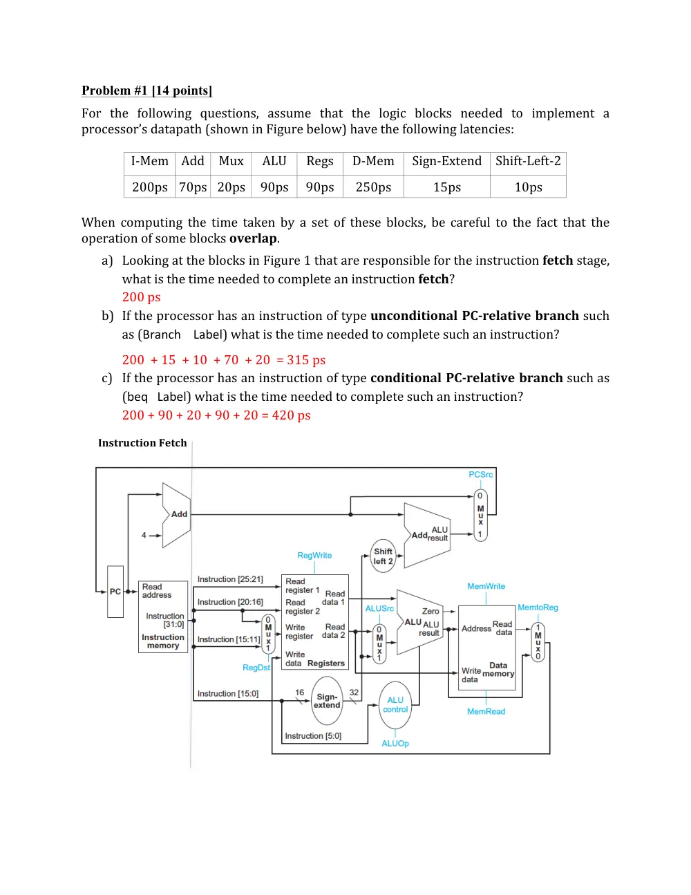
Problem #1 [14 points]
For
the
following
questions,
assume
that
the
logic
blocks
needed
to
implement
a
processor’s
datapath
(shown
in
Figure
below)
have
the
following
latencies:
I-‐Mem
Add
Mux
ALU
Regs
D-‐Mem
Sign-‐Extend
Shift-‐Left-‐2
200ps
70ps
20ps
90ps
90ps
250ps
15ps
10ps
When
computing
the
time
taken
by
a
set
of
these
blocks,
be
careful
to
the
fact
that
the
operation
of
some
blocks
overlap.
a) Looking
at
the
blocks
in
Figure
1
that
are
responsible
for
the
instruction
fetch
stage,
what
is
the
time
needed
to
complete
an
instruction
fetch?
200
ps
b) If
the
processor
has
an
instruction
of
type
unconditional
PC-‐relative
branch
such
as
(Branch
Label)
what
is
the
time
needed
to
complete
such
an
instruction?
200
+
15
+
10
+
70
+
20
=
315
ps
c) If
the
processor
has
an
instruction
of
type
conditional
PC-‐relative
branch
such
as
(beq
Label)
what
is
the
time
needed
to
complete
such
an
instruction?
200
+
90
+
20
+
90
+
20
=
420
ps
Instruction
Fetch
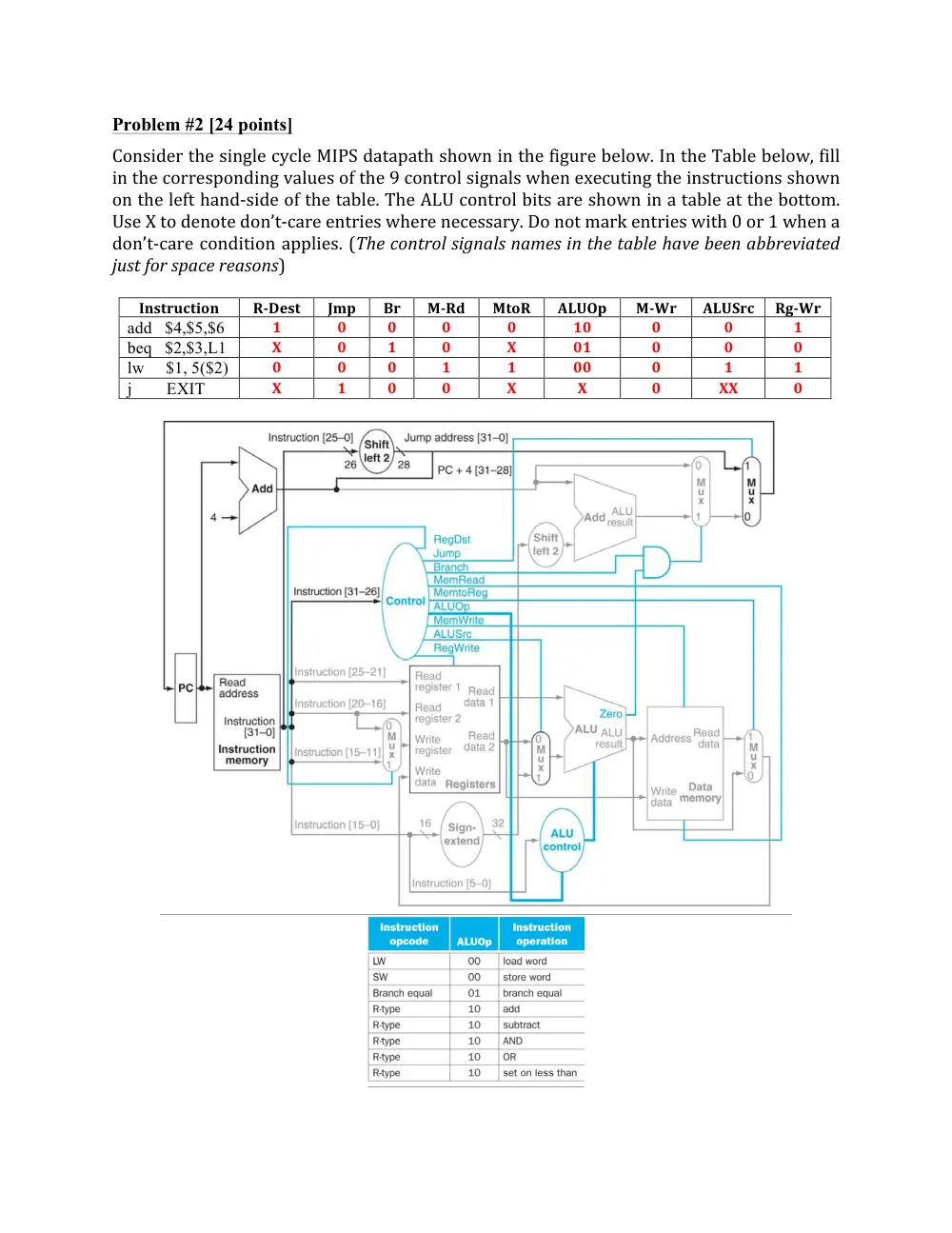
Problem #2 [24 points]
Consider
the
single
cycle
MIPS
datapath
shown
in
the
figure
below.
In
the
Table
below,
fill
in
the
corresponding
values
of
the
9
control
signals
when
executing
the
instructions
shown
on
the
left
hand-‐side
of
the
table.
The
ALU
control
bits
are
shown
in
a
table
at
the
bottom.
Use
X
to
denote
don’t-‐care
entries
where
necessary.
Do
not
mark
entries
with
0
or
1
when
a
don’t-‐care
condition
applies.
(The
control
signals
names
in
the
table
have
been
abbreviated
just
for
space
reasons)
Instruction
R-‐Dest
Jmp
Br
M-‐Rd
MtoR
ALUOp
M-‐Wr
ALUSrc
Rg-‐Wr
add $4,$5,$6
1
0
0
0
0
10
0
0
1
beq $2,$3,L1
X
0
1
0
X
01
0
0
0
lw $1, 5($2)
0
0
0
1
1
00
0
1
1
j EXIT
X
1
0
0
X
X
0
XX
0
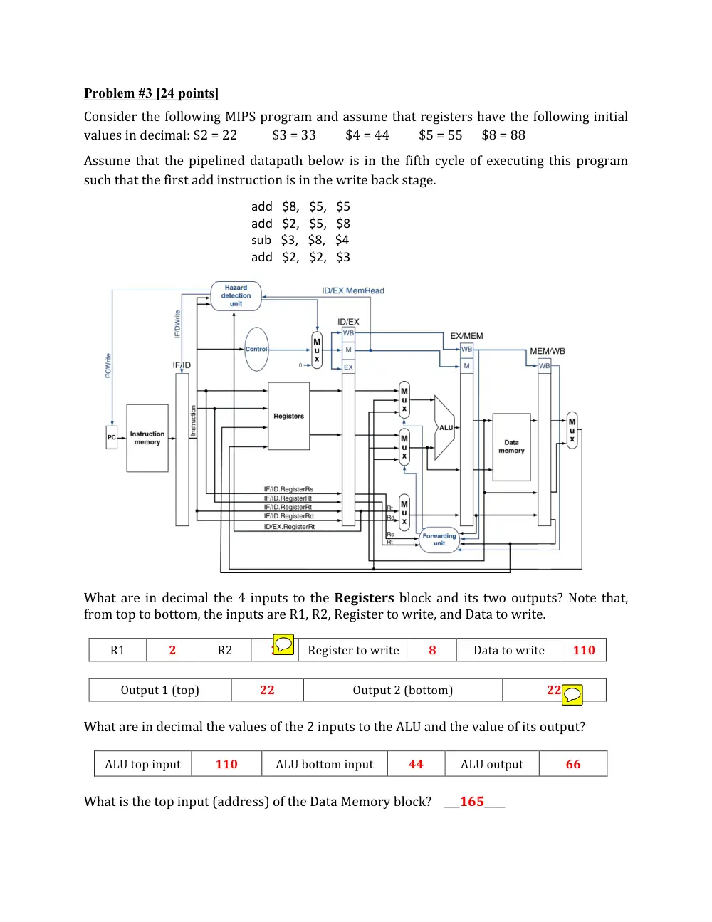
Problem #3 [24 points]
Consider
the
following
MIPS
program
and
assume
that
registers
have
the
following
initial
values
in
decimal:
$2
=
22
$3
=
33
$4
=
44
$5
=
55
$8
=
88
Assume
that
the
pipelined
datapath
below
is
in
the
fifth
cycle
of
executing
this
program
such
that
the
first
add
instruction
is
in
the
write
back
stage.
add
$8,
$5,
$5
add
$2,
$5,
$8
sub
$3,
$8,
$4
add
$2,
$2,
$3
What
are
in
decimal
the
4
inputs
to
the
Registers
block
and
its
two
outputs?
Note
that,
from
top
to
bottom,
the
inputs
are
R1,
R2,
Register
to
write,
and
Data
to
write.
R1
2
R2
2
Register
to
write
8
Data
to
write
110
Output
1
(top)
22
Output
2
(bottom)
22
What
are
in
decimal
the
values
of
the
2
inputs
to
the
ALU
and
the
value
of
its
output?
ALU
top
input
110
ALU
bottom
input
44
ALU
output
66
What
is
the
top
input
(address)
of
the
Data
Memory
block?
___165____
Problem #4 [14 points]
We would like to examine the accuracy of various branch predictors. Assume that we have 5
branch instructions in a loop and the outcomes of these branches are always: T, NT, T, T, NT.
a) What is the accuracy of the always-taken predictor for this sequence of branch outcomes?
Answer
3/5
b) What is the accuracy of the always-not-taken predictors for this sequence of branch
outcomes?
Answer
2/5
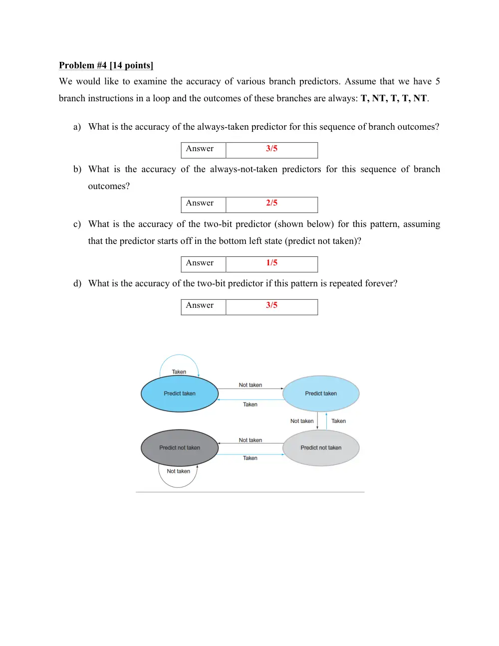
c) What is the accuracy of the two-bit predictor (shown below) for this pattern, assuming
that the predictor starts off in the bottom left state (predict not taken)?
Answer
1/5
d) What is the accuracy of the two-bit predictor if this pattern is repeated forever?
Answer
3/5
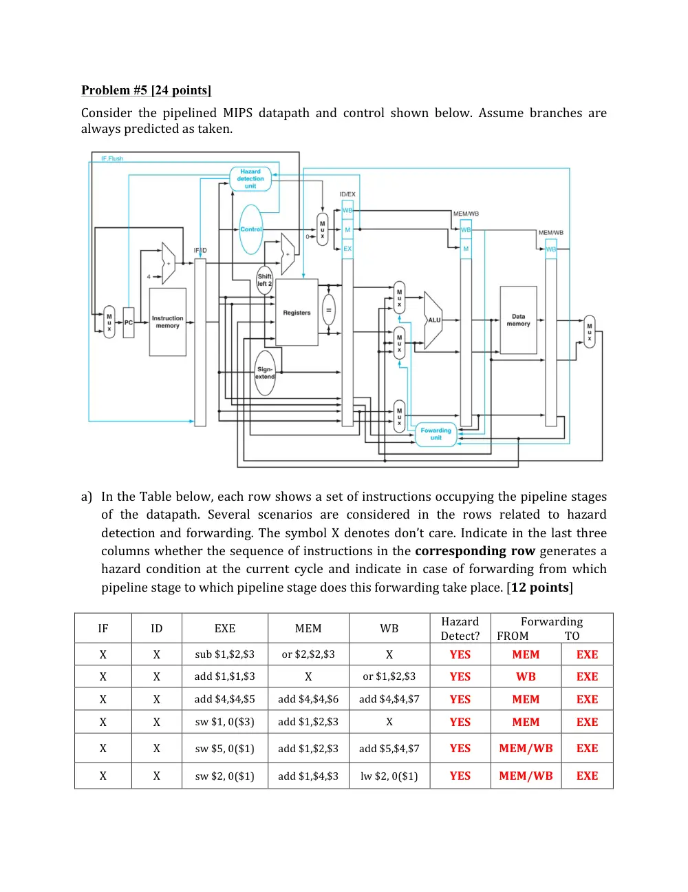
Problem #5 [24 points]
Consider
the
pipelined
MIPS
datapath
and
control
shown
below.
Assume
branches
are
always
predicted
as
taken.
a) In
the
Table
below,
each
row
shows
a
set
of
instructions
occupying
the
pipeline
stages
of
the
datapath.
Several
scenarios
are
considered
in
the
rows
related
to
hazard
detection
and
forwarding.
The
symbol
X
denotes
don’t
care.
Indicate
in
the
last
three
columns
whether
the
sequence
of
instructions
in
the
corresponding
row
generates
a
hazard
condition
at
the
current
cycle
and
indicate
in
case
of
forwarding
from
which
pipeline
stage
to
which
pipeline
stage
does
this
forwarding
take
place.
[12
points]
IF
ID
EXE
MEM
WB
Hazard
Detect?
Forwarding
FROM
TO
X
X
sub
$1,$2,$3
or
$2,$2,$3
X
YES
MEM
EXE
X
X
add
$1,$1,$3
X
or
$1,$2,$3
YES
WB
EXE
X
X
add
$4,$4,$5
add
$4,$4,$6
add
$4,$4,$7
YES
MEM
EXE
X
X
sw
$1,
0($3)
add
$1,$2,$3
X
YES
MEM
EXE
X
X
sw
$5,
0($1)
add
$1,$2,$3
add
$5,$4,$7
YES
MEM/WB
EXE
X
X
sw
$2,
0($1)
add
$1,$4,$3
lw
$2,
0($1)
YES
MEM/WB
EXE
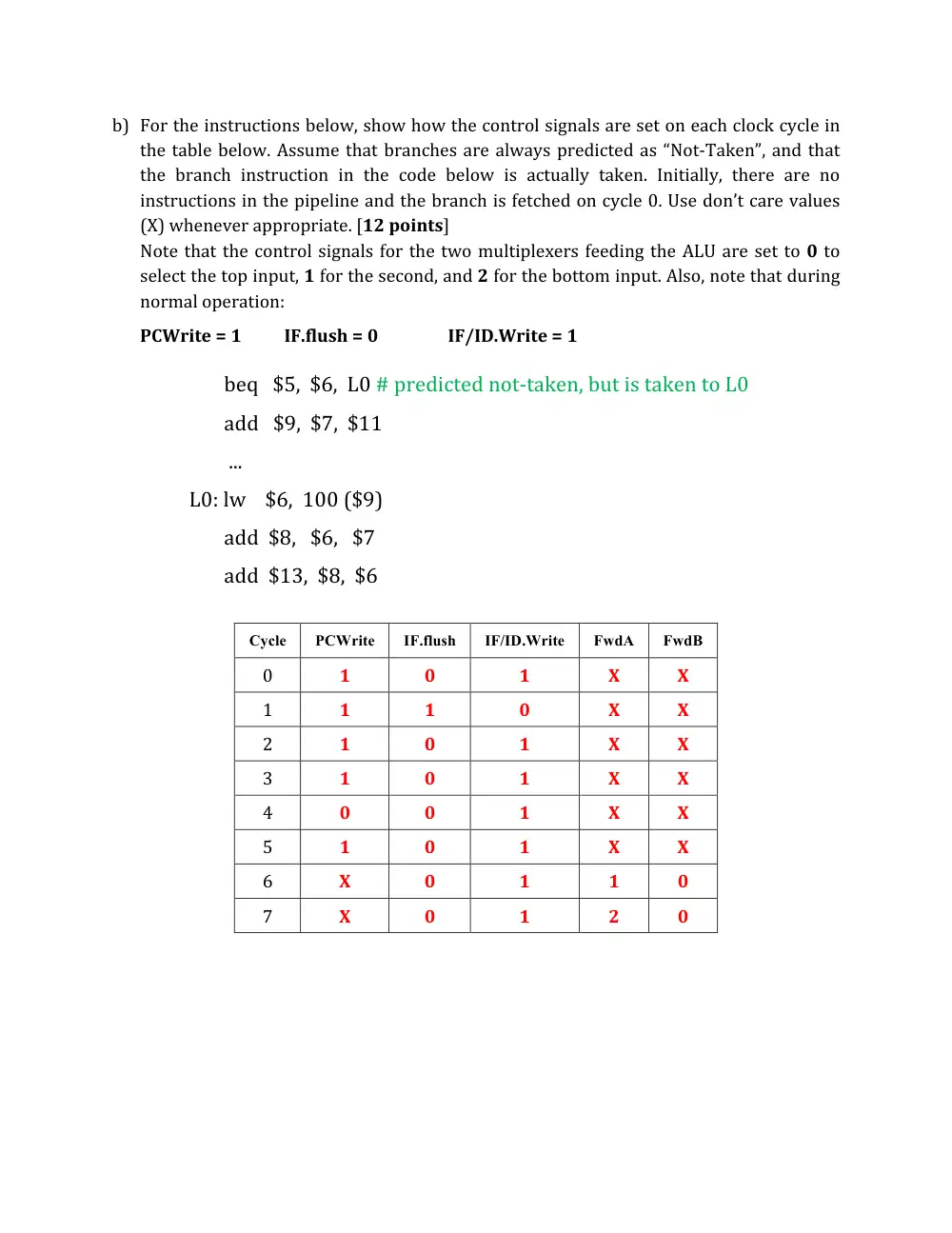
b) For
the
instructions
below,
show
how
the
control
signals
are
set
on
each
clock
cycle
in
the
table
below.
Assume
that
branches
are
always
predicted
as
“Not-‐Taken”,
and
that
the
branch
instruction
in
the
code
below
is
actually
taken.
Initially,
there
are
no
instructions
in
the
pipeline
and
the
branch
is
fetched
on
cycle
0.
Use
don’t
care
values
(X)
whenever
appropriate.
[12
points]
Note
that
the
control
signals
for
the
two
multiplexers
feeding
the
ALU
are
set
to
0
to
select
the
top
input,
1
for
the
second,
and
2
for
the
bottom
input.
Also,
note
that
during
normal
operation:
PCWrite
=
1
IF.flush
=
0
IF/ID.Write
=
1
beq
$5,
$6,
L0
#
predicted
not-‐taken,
but
is
taken
to
L0
add
$9,
$7,
$11
...
L0:
lw
$6,
100
($9)
add
$8,
$6,
$7
add
$13,
$8,
$6
Cycle
PCWrite
IF.flush
IF/ID.Write
FwdA
FwdB
0
1
0
1
X
X
1
1
1
0
X
X
2
1
0
1
X
X
3
1
0
1
X
X
4
0
0
1
X
X
5
1
0
1
X
X
6
X
0
1
1
0
7
X
0
1
2
0