
EECE 370 Lecture, Spring 2008
American University of Beirut · Electric Machines and Power Fundamentals · 13 pages


Showing the first 10 of 13 pages. Download the PDF to see all of it.
More EECE 370 files
Show the text of this lab
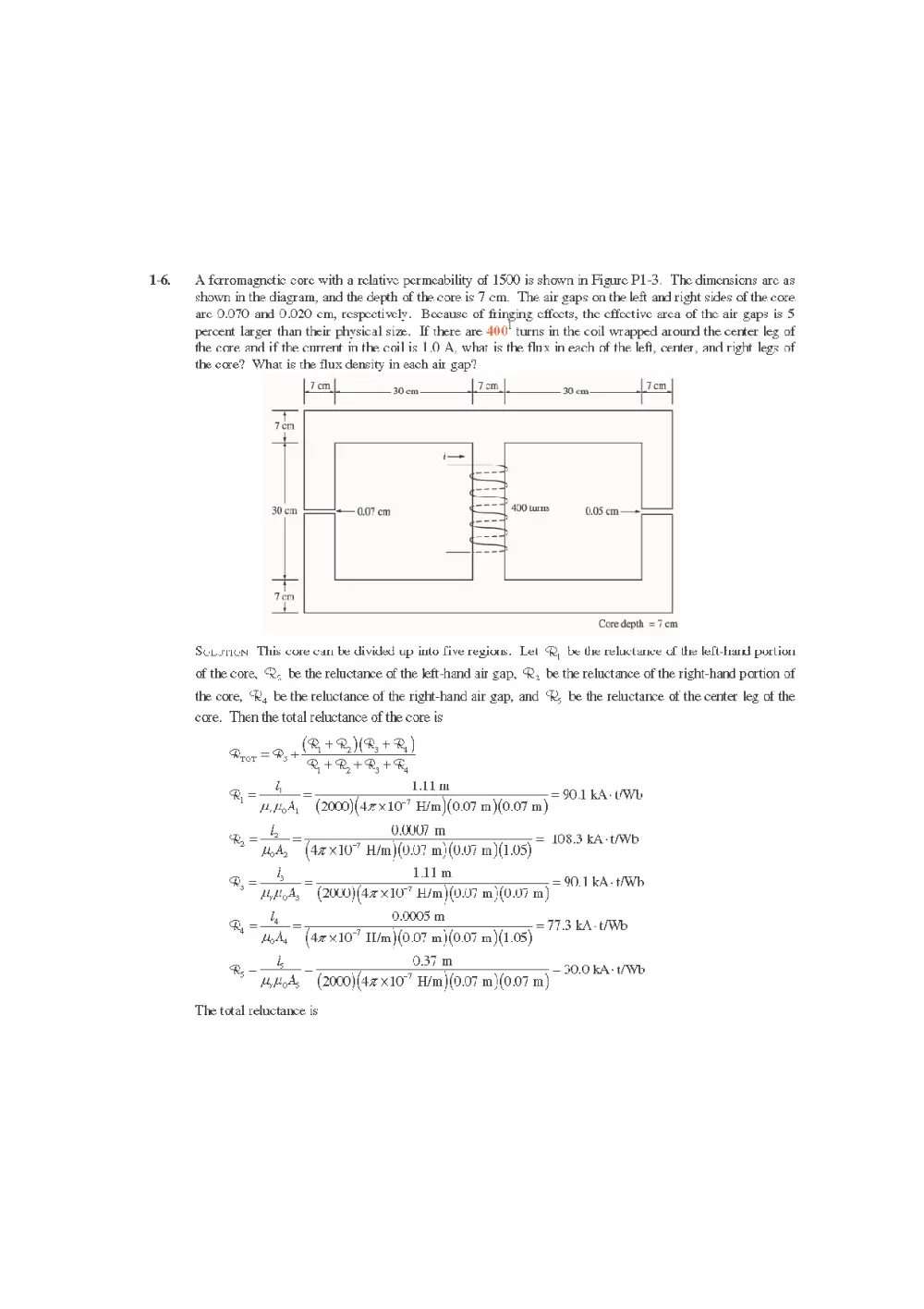
A ferromagnetic core with a relative permeability of 1590 is shown in Figure P1-3, The dimensions are as
shown in the diagram, and the depth of the core is 7 cm. The air gaps on the left and right sides of the core
are 0.070 and 9.020 cm, respectively. Because of fringing effects, the effective area of the air gaps is 5
percent larger than their physical size. If there are 400! turns in the coil wrapped around the center leg of
the core and if the current in the coil is 1.0 A, whar is the flix in each of the left, center, ancl right legs of
the core? What is the flux density in each air gap?
Le cm. 30cm 1 om, 20 cm. 7cm,
30cm 0.07 cm 0.05 cm —=
Core depth =7 cm
ScLorien This core can be divided up into live regious. Let Q, be the reluctance of the left-hand portion
of the core, . be the reluctance of the left-hand air gap, ®, be the reluctance of the right-hand portion of
the core, R, be the reluctance of the right-hand air gap, and ‘R; be the reluctance of the center leg of the
cae. Then the total reluctance of the core is
+ Rt
4, =o, (RA ENB+R)
RAR +R, +R,
i, L.illm
g-—_- = 90.1 kA-UWb
© BoA, (2000)(42x107 H/m)(0.07 m)(0.07 m)
b 0.0007 m
= ‘ : = 108.3 kA-tAVD
% Hod, (42107 H/m)(0.07 mi(0.07 m)(1.05)
@,=-—b_= Aim = 0.1 kA-HWh
HyflgA, (2000)(42 x10 H/m)(0.07 m}(0.07 m)
@, == 2.0005 m =71.3 kA-tAWb
Hod, (42107 I1/m)(0.07 mj (0.07 m)(1.05)
@,-—+ 9.37 m — 30.0 kA: tb
© tykods — (2000)(42 x10” H/m)(0.97 m\(0.07 m)
The total reluctance is
(R+BMB+2B)_ 30.0 (90.1+108.3)(90.1+77.3)
=30.0+ =1208 kA-t/Wb
R+R+R+P 90.1+1083+90.1+773
Rror = Rs +
The total flux in the core is equal to the flux in the center leg:
S _ (400t)(1.0 A)
roster = Gror =
= = 0.0033 Wb
Riop 120.8 KA- AW
The fluxes in the left and right legs can be found by the “flux divider rule”, which is analogous to the
current divider rule.
(QR, +2) 7 (90.1+77.3)
Dee = or= (0.0033 Wb) = 0.00193 Wb
Qi+ PR, +2, +®, 90.1+108.3+90.1+77.3
R+® 90.1+108.3
oat = (B+) Prop = ( ) (0.0033 Wb) = 0.00229 Wb
R+Rt+zRB+aR 90.1+108.3+ 90.1+773
The flux density in the air gaps can be determined from the equation ¢= BA:
— Por _ 0.00193 Wb
Ay, (0.07 em)(0.07 cm)(1.05)
Ben =0375T
p= frst 0.00229 Wb
= Fam _ =0.445T
"Ag (0.07 cm)(0.07 cm)(1.05)
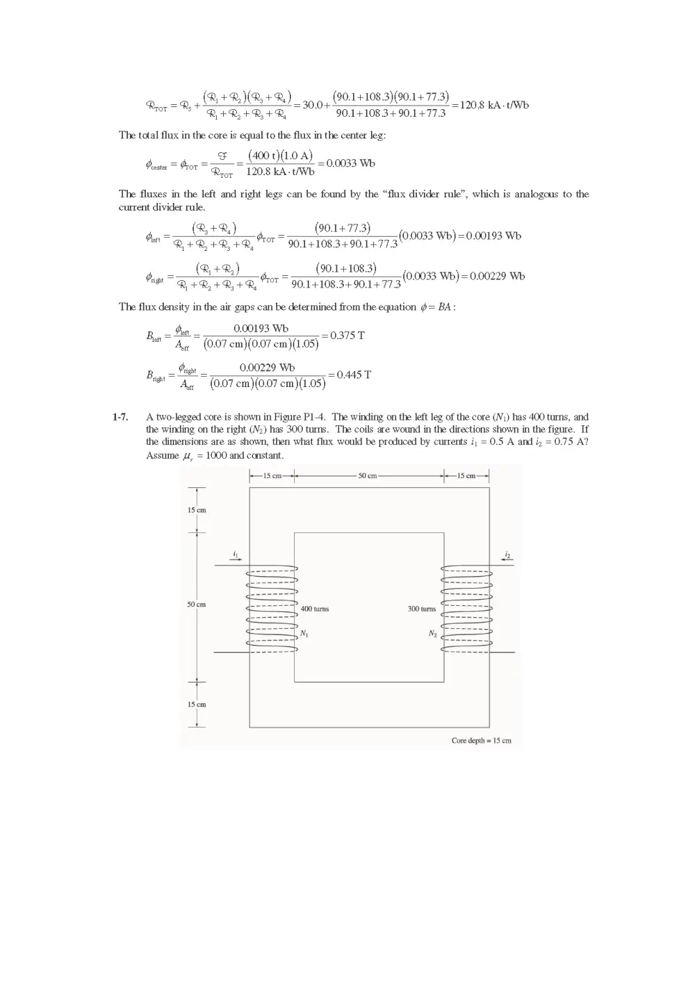
1-7. A two-legged core is shown in Figure P1-4. The winding on the left leg of the core (N,) has 400 turns, and
the winding on the right (V2) has 300 turns. The coils are wound in the directions shown in the figure. If
the dimensions are as shown, then what flux would be produced by currents i; = 0.5 A and i, = 0.75 A?
Assume 4é, = 1000 and constant.
15 cm—+ 50cm. j-—15 cm—>+
15cm
50cm
15cm
Core depth = 15 cm
SoLution The two coils on this core are would so that their magnetomotive forces are additive, so the total
magnetomotive force on this core is
Spor = Ny + Noiy = (400 t)(0.5 A+ (300 t)(0.75 A)=425 A-t
The total reluctance in the core is
Reon =— 2.60 m = 92.0 kA- Wb
"tt (1000)(42 x10" H/m)(0.15 m)(0.15 m)
and the flux in the cote is:
g= Stor -_ 454 t _ooo462 wo
Rrop 920KA-t/Wb
1-8. A cove with three legs is shown in Figure P1-5. Its depth is 5 cm, and there are 200 turns on the lettmost
leg. The relative permeability of the core can be assumed to be 1500 and constant. What flux exists in
each of the three legs of the core? What is the flux density in each of the legs? Assume a 4% increase in
the effective area of the air gap due to fringing effects.
jem 25 om -|-— 15 em—-+|- 25 cm fen
t
9cm
i |
200 tums -— 0.04 cn 25cm
Sem
Core depth Scm
So.urton This core can be divided up into four regions. Let “X, be the reluctance of the left-hand portion
of the core, SR, be the reluctance of the center leg of the core, “2, be the relnctance of the center air gap,
and ‘, be the reluctance of the right-hand portion of the core. Then the total reluctance. of the core is
Bye D4 Ret BIR
. R+R+R,
Q-—_ LOS m -1273 kA-tWE
HMA, (1500)(4-e% 10 * H/m)(0.09 m)(C.05 m)
L 034m
woe = ~ = 24.0 kA-tiWb
% Hod — (1500)(4% 107 H/m)(0.15 m)(0.95 m}
Z 0.0004 m
RQ, == - —— = 40,3 KA-UWb
° ibd (42x10 Him)(0.15 m)(0.05 m)(1.04)
R,-—" Len --127.3 KA-tAVb
4
© HilloAg (1500)(42x107 Him) (0.09 m)(0.05 m)
The total reluctance is
R,+D)R 24.0+ 40.8)127.3
( 2 3 4
Riot =P, + =127.3+ =170.2 kA-t/Wb
R+R,+R, 24.04+40.8+1273
The total flux in the core is equal to the flux in the left leg:
& _ (200t)(2.0 A)
$0 = Pron =D
= =0,00235 Wb
Roop 170.2 KA-tAWD
The fluxes in the center and right legs can be found by the “flux divider rule”, which is analogous to the
current divider rule.
R, 1273
= = 0.00235 Wb) = 0.00156 Wb
Poste R, +2, +®, trot = 5404408 vias! )
Rt+R, 24.0+ 40.8
= = 0.00235 Wb) = 0.00079 Wb
Poa R +R, +R, Gror 70+408+1273' )
The flux density in the legs can be deter mined from the equation ¢ = BA:
p= fer 0.00235 Wo _ oso
A (0.09 cm)(0.05 cm)
p,, =fas = O.001S6 WE _ 9 0g 7
A (0.15 cm)(0.05 cm)
B,,, = ft = 0.00079 Wo _ 6 7
sa" 4 (0.09 cm) (0.05 cm)
1-12. The core shown in Figure P1-4 is made of a steel whose magnetization curve is shown in Figure P1-9.
Repeat. Problem 1-7, but this time do not assime a constant. valne of py. How much fin is prociced in the
care by the currents specified? What is the relative permeability of this core uncer these corclitions? Was
the assumption in Problem 1-7 that the relative permeability was equal to 1000 a gocd assumption for these
conditions? Ts ita gor assumption in general?
15 cm—+ 50cm j+—15 cm.
15cm
v
15cm
Core depth = 15 cm
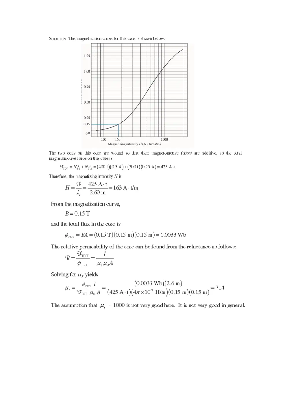
SoLuTion The maguelizalion cur ve for Lhis core is shown below:
1.25 ZA
: 4
> 0.75
1 0.50
0.25
0.15
0.0
100 163 1000
Magnetizing intensity H (A - turns/m)
The two coils on this core are wound su thal their maguelomolive furces are additive, so the total
Inagnuelomoti ve Lorce on lis core is
Troe = Ni + Nii, = (400 t)(0.5 A)+ (300t)(0.75 A)=425 A-t
Therefore, the magnetizing intensity 1 is
SF 425A-t
H=-—=—
=163A-tim
, 60m
From the magnetization curve,
B=0.15T
and the lotal Mux in the cure is
Qrop = BA = (0.15 T)(0.15 m}(0.15 m)= 0.0033 Wb
The relative permeability of the core can be found from the reluctance as follows:
Pre Hy byA
Solving for yu, yields
u Drop bo (0.0033 Wb)(2.6 m) _.
~ Gror Hy A (425 A-O(4rx107 Hu )(0.15 m)(0.15 m)
The assumption that ££, = 1000 is not very good here. It is not very good in general.
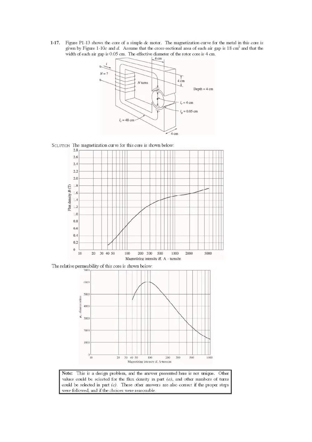
1-17. Figure P1-13 shows the core of a simple de motor. The magnetization curve for the metal in this core is
given by Figure 1-10c and d. Assume that the cross-sectional area of each air gap is 18 cm’ and that the
width of each air gap is 0.05 cm. The effective diameter of the rotor core is 4 cm.
4cm
pi"
Depth = 4cm
1=4cm
}~ 1, = 0.05 cm
=
4cm
ScLuvion ‘The magnetization cur ve for this core is shown below:
28
2.6
2.4
22
2.0
L8
16 —_——
14 Lert a
12 AC
1.0
0.8
0.6
0.4
0.2
Flux density B (T)
0
10 20 30 40 50 100 =200 300 500 1000 2000 5000
Magnetizing intensity H, A - turns/m
The relative permeability of this core is shown below:
700)
00)
400) \
300)
700)
1009
10 20 30 40 50 100 200-300 500 1000
Magretizing intensity 1, A-turns/m
Note: This is a design problem, and the answer presented here is not unique. Other
yalues could be selected for the flux density in part (@), and other numbers of turns
could be selected in part (c). These other answers are also correct if the proper steps
wete followed, and if the choices were. reasonable.
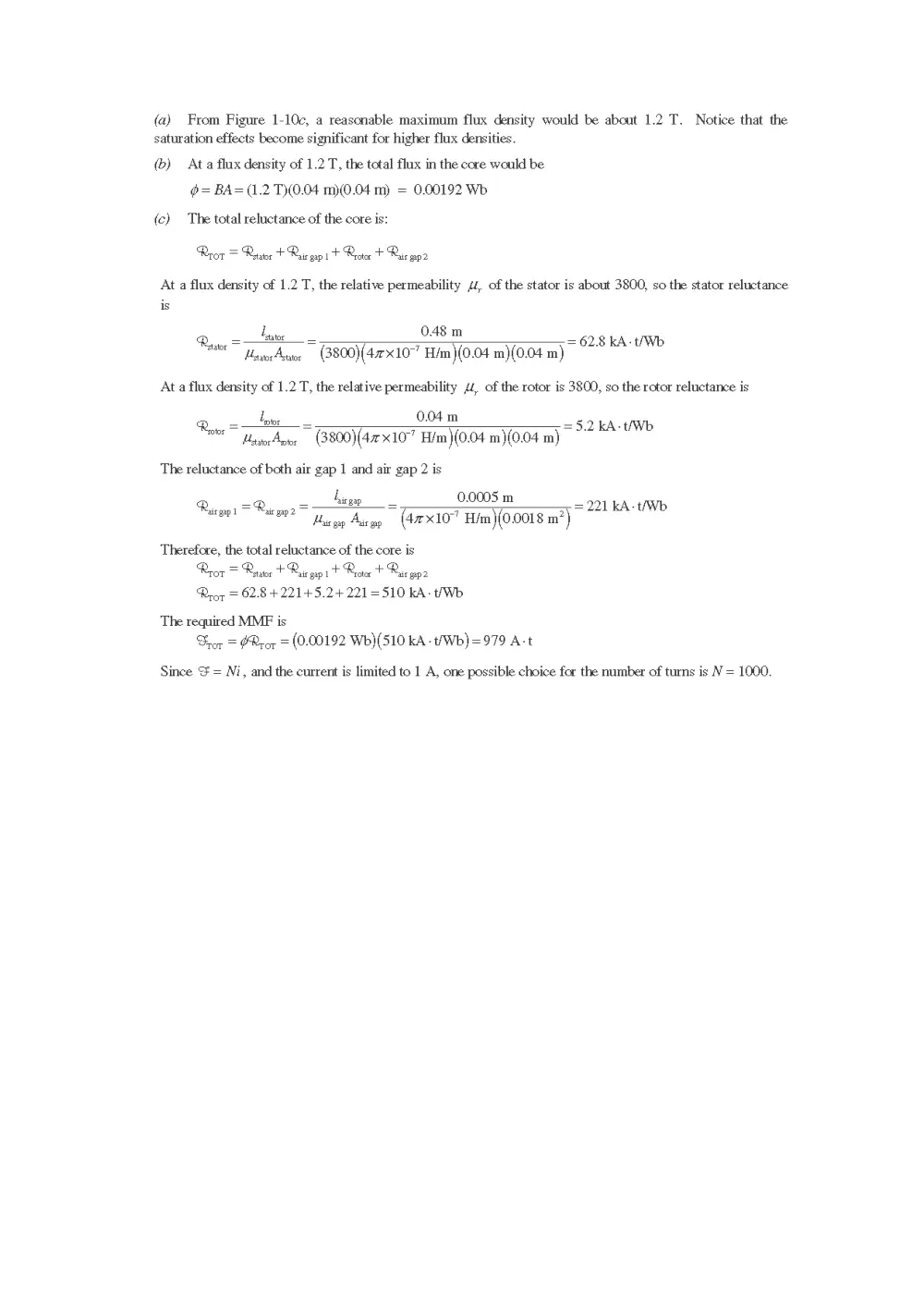
(a) From Figure 1-10c, a reasonable maximum flux density would be about 1.2 T. Notice that the
saturation effects become significant for higher flux densities.
(6) Ata flux density of 1.2 T, the total flux in the core would be
$= BA= (1.2 T)(0.04 m)(0.04 m) = 0.00192 Wb
(c) The total reluctance of the core is:
Rror = Reator + Raic epi t Reotor + Rai gap2
At a flux density of 1.2 T, the relative permeability 44, of the stator is about 3800, so the stator reluctance
is
i 0.48
Resto = — Se = ~ = 62.8 kA-t/Wb
HestocAwor (3800)(4x10⁷ Him )(0.04 m)(0.04 m)
At a flux density of 1.2 T, the relative permeability £2, of the rotor is 3800, so the rotor reluctance is
lar 0.04 m
toe =5.2 KA-t/Wb
Rove HasocAgor (3800)(42x107 H/m)(0.04 m)(0.04 m)
The reluctance of both air gap 1 and air gap 2 is
L
Rig gap = —t = 0.0005 m = 221 kA-t/Wb
R eT hg Aveog (4X10 Him)(0.0018 m’)
‘air gap 1
Therefore, the total reluctance of the core is
Rror = Reaor + Rais wpit Rector + R,
"ais gap 2
Rrop = 62.8+221+5.2+221 =510 kA- Wh
The required MMF is
ror = GRror = (0.00192 Wh)(5S10 kA t/Wb)=979 A-t
Since & = Ni, and the current is limited to 1 A, one possible choice for the number of turns is N = 1000.
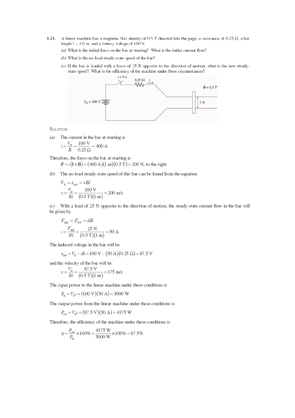
1-21. A linear machine has a magnetic flix density of 0.5 T directed into the pagp, a resistance of 0.25 ©, a bar
length ? = 1.0 m, andl a battery voltage of 100 V.
(a) What is the initial force on the bar at starting? What is the initial current flow?
(6) What is the no-load steady-state. speed of the bar?
(c) If the bar is loaded with a force of 25 N opposite to the direction of motion, what is the new steady-
state speed? What is the efficiency of the machine under these circumstances?
t=0s
x 0.252 i
B=05T
Vp, = 100 V == Im
SOLUTION
(a) The current in the bar at starting is
Therefore, the force on the bar at starting is
F=i(1xB)= (400 A)(1 m)(0.5 T) = 200 N, to the right
(b) The no-load steady-state speed of this bar can be found from the equation
V, =vBl
Being
pave V0 ms
BL (05ST) m)
(c) With a load of 25 N opposite to the direction of motion, the steady-state current flow in the bar will
be given by
Fy, = Fy = UB
. Fg -25N
i= Pi “stm
The induced voltage in the bar will be
lng = Vz —iR =100 V - (50 A)(0.25 Q)=87.5V
and the velocity of the bar will be
V,__875V
== SY 175 ms
*“B (OST) m) ‘
The input power to the linear machine under these conditions is
P, =V,i = (100 V)(50 A)= 5000 W
The output power from the linear machine under these conditions is
P,,, =V,i = (87.5 V)(50 A) =4375 W
Therefore, the efficiency of the machine under these conditions is
p= Fat 100% = 875. W
P 5000 W
in
x 100% =87.5%
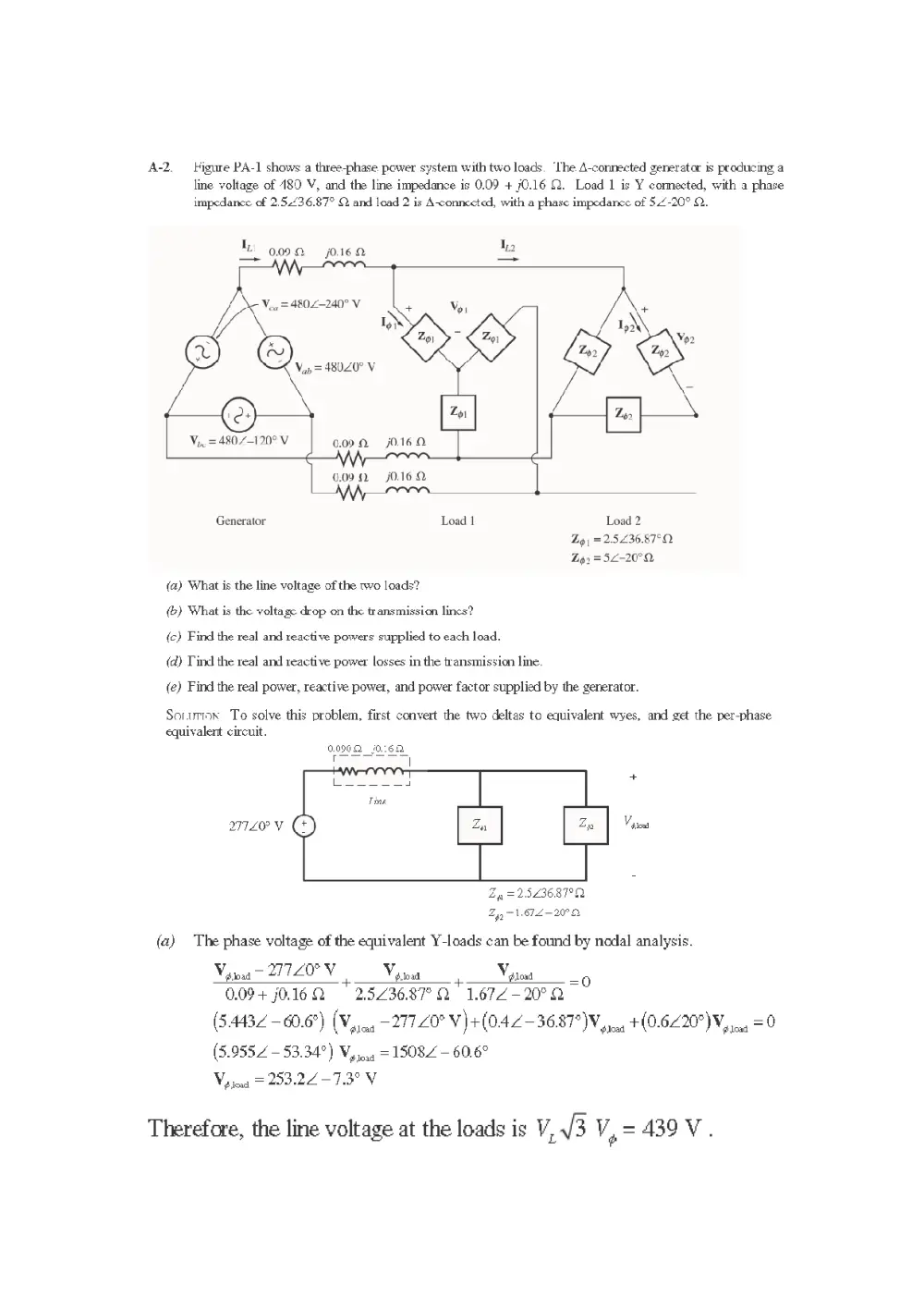
A-2. — Higure PA-1 shows a three-phase power system with two loads. ‘The A-connected generator is producing a
line voltage of 189 V, and the line impedance is 0.09 + 70.16 ©. Load 1 is Y cormected, with a phase
impedance of 2.5.436.87° Q and load 2 is A-connected, with a phase impedance of 5.4-20° 2.
1 o090a j0.16.2 Ie
— A =
L Vo
Vou = 4802-240" V
\ MSS | ACM Aw.
() Chenery SR
@) [
V,,. = 4807—-120° V 6.002 j0.160
MWA
0.092 j0.16 2
Generator Load | Load 2
Zo) =2.5236.87°Q
Zo. = 52-20°2
(a) What is the line voltage of the two loads?
(&) What is the voltage drop on the transmission lincs?
(c) Find the real and reactive powers supplied to each load.
(@) Tind the real and reactive power losses in the transmission line.
(e) Find the real power, reactive power, and power factor supplied by the generator.
Sonurmnx To solve this problem, first convert the two deltas to equivalent wyes, and get the per-phase
equivalent circuit.
0.090Q 10:62
Zq_ =2523687°Q
2 yy = 1.67.2 - 20°
(a) The phase voltage of the equivalent Y-loads can be found by nodal analysis.
Vo oaa ~ 27720° V nm Voy tos n Vp toad
0.09+ j0.16Q = 2.523687 Q 1.672-20°2
(5.4432 -60.6°) (Vy, -277.20° V) +(04 2-36.87 WV yy.45 +(0.6220°V, 44 = 0
(5.9552 — 53.34°) V,..., = 15082 — 60.6°
load
Vora = 253.22 —7.3° V
Therefore, the line voltage at the loads is V, 3 V, -4390V.
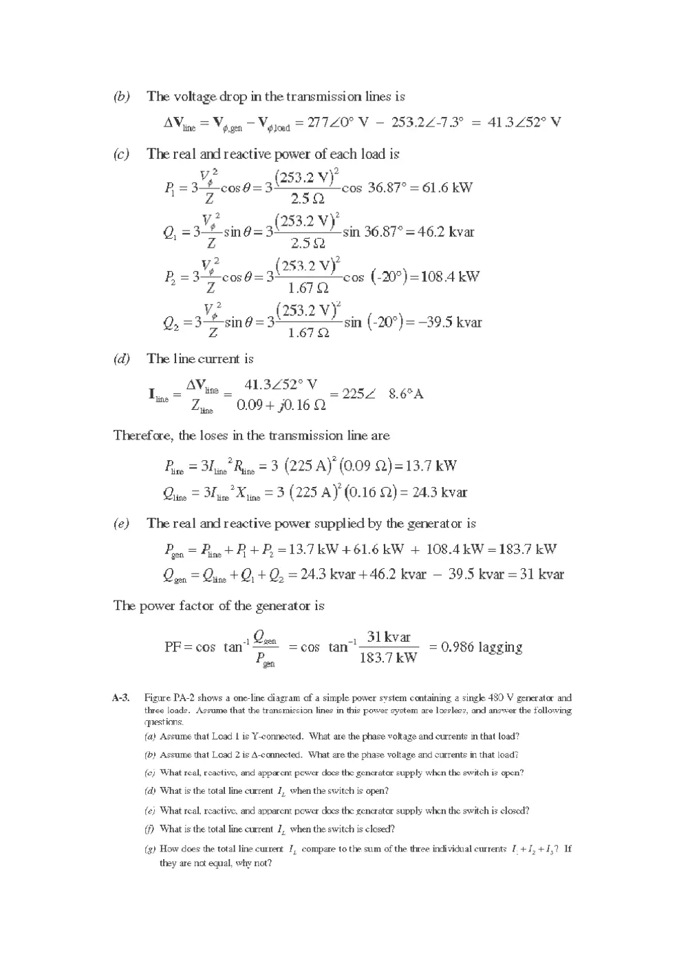
(b) The voltage drop in the transmission lines is
AVine = Vocen — Vipjaa = 27720" V — 253.22-7.3° = 413.252° V
(ec) The real and reactive power of each load is
y2 2
Fo=3 é cos = 3082 Y) cos 36.87° = 61.6 kW
Z 250
v, 253.2 VY)
Q, =3— sing=3! ) sin 36.87° = 46.2 kvar
Z 2.5
P 83M 59-32 og (-20°) =108.4 kW
= = =108.
Z 1.67
v, 253.2 Vy
Q,=3—+ sing =3! } sin (-20°)=—39.5 kvar
A 1.672
(dq) The line current is
AY, 41.3252° V
line _
I. = = : = 2257-8.6°A
Zine 0.09 + 70.16 2
Therefore, the loses in the transmission line are
Pore = Blinn’ Rugs = 3 (225 AY (0.09 2.)=13.7 kW
rice = Bice’ Kine = 3 (225 AY (0.16 Q) = 24.3 kvar
(e) The real and reactive power supplied by the generator is
Pon = Fine + A +P, =13.7 KW + 61.6 kW + 108.4 kW = 183.7 kW
Qven = Qiine + Q, + Q, = 24.3 kvar + 46.2 kvar — 39.5 kvar = 31 kvar
The power factor of the generator is
. 31k
PF=cos tan” ae =cos tan 17 Va 0.986 lagging
Pros 183.7 kW
A-3. Figure PA-2 shows a one-line diagram of a simple power system containing a single 480 V generator and
three loads. Assume that the transmission lines in this power system are lossless, and answer the following
questions.
(a) Assume that Load | is Y-connected. What are the phase voltage and currents in that load?
(b) Assume that Load 2 is A-connected. What are the phase voltage and currents in that load?
fe) What real, reactive, and apparent power does the generator supply when the switch is open?
(a) What is the total line current 7, when the switch is open?
fe) What real, reactive, and apparent pewer docs the generator supply when the switch is closed?
(f) What is the total line current 7, when the switch is closed?
(g) How does the total line current [, compare to the sum of the three individual currents 1. +J,+4,? If
they are not equal, why not?