
EECE 370 Lecture, Spring 2008
American University of Beirut · Electric Machines and Power Fundamentals · 18 pages




Showing the first 10 of 18 pages. Download the PDF to see all of it.
More EECE 370 files
Show the text of this lab
A 1000-VA 230/115-¥ transformer has been tested to determine its equivalent circuit. The results of the
tests are shown below.
Open-circuit test Short-circuit test
Voc = 230 V Vso = 19.1 V
Toco =OA5A Isc =8.7 A
Poo = 30 W Pso = 42.3 W
All data given were taken from the primary side of the transformer.
(a) Find the equivalent circuit of this transformer referred to the low-voltage side of the transformer.
(b) Find the transformer’s voltage regulation at rated conditions and (1) 0.8 PF lagging, (2) 1.0 PF, (3) 0.8
PF leading.
(c) Determine the transformer’s efficiency at rated conditions and 0.8 PF lagging.
SOLUTION
(a) OPEN CIRCUIT TEST:
045A
Yox| = |G. — JBy| = = 0.001957
Heel = [Ge ~ JBy| = 9
@=cos™ Foo =cos™ 30W = 73.15°
Vooloo (230V\0OA5A)
Vax = Go — jBy = 0.001957Z — 73.15° mho = 0.000567 - j0.001873 mho
Ro= 1 =17632
G,
SHORT CIRCUIT TEST:
191¥
[Ziq] =|Req + Xzo| =F 722
@=cos Fee cos! 423 W = 75,3°
Veoloc (19.1 V)(B7 A)
Zug = Rag + (Xgq = 2.20275.3° 2 =0.558+ j2.128Q
Reg = 0.5582
Xgq = j2.1282
To convert the equivalent circuit to the secondary side, divide each impedance by the square. of the turns
ratio (a = 230/115 = 2). The resulting equivalent circuit is shown below:
al, F I
col Ras Kegs SS
+0 l AM, SYN. O+
"Sk PS v.
a ac o
-o l R oO-
(b) Regs = 3 + Rs
Ȣ
Xe = = + Xz
Reg, = 0.1402 Xag, = j0.532Q
R,, = 4410 X yy, =I
(b) To find the required voltage regulation, we will use the equivalent circuit of the transformer referred
to the secondary side. The rated secondary current is
7, = 1000VA _g aga
*T1SV
We will now calculate the primary voltage referred to the secondary side and use the yoltage regulation
equation for each power Factor.
() 0.8 PF Lagging:
V, =V,+Zpqly =HS20°V + (0.140 + j0.532.2)(8.72—36.87° A)
V, -1188A14°V
= NEES 100% =3.3%
(2) 1.0 PR:
vy, =Y, + Zugls =11520° V + (0.140 + j0.532Q)(8.7.20° A)
V,. =116.322.28° V
_ 1163-115
~ 115
(3) 0.8 PF Leading:
VR x 100% = 1.1%
Vv, =¥, +Zagls =11520° V + (0.140 + j0.532 Q)(8.7236.87° A)
V, =113.322.24° V
_ 113.3415
115
(ce) At rated conditions and 0.8 PF lagging, the output power of this transformer is
=V,1, cos @=(115 V)(8.7 A)(0.8)= 800 W
VR x 100% =-1.5%
P
OUT
The copper and core losses of this transformer are
Poy = 1g? Rags =(8.7 AY (0.140 Q)=10.6 W
r\2
(V, | (118.8 V)’
Po = =+—""/ _320W
R, 441 Q
Therefore the efficiency of this transformer at these conditions is
Four x100% = 800 W = 94.9%
Pour + Peay + Fore 800 W + 10.6 W + 320W
R=
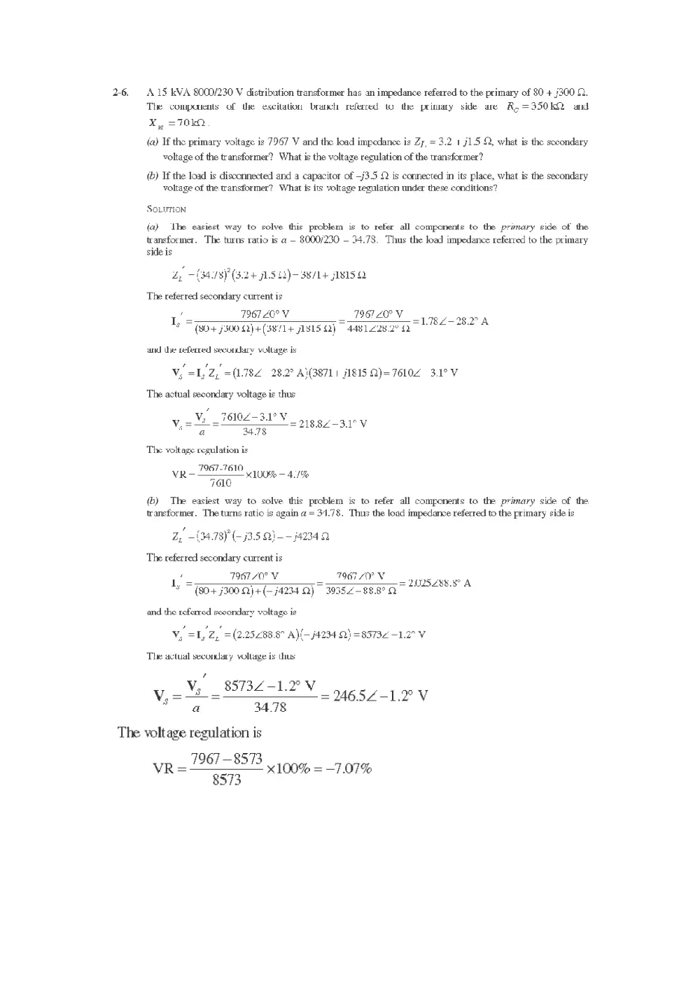
2-6 A.15 kVA 8000/230 V distribution transformer has an impedance referred to the primary of 80 + (300 ©.
The companents of the excitation branch referred to the primary side are R,=350kKQ and
Xy =70kO
(a) If the primary voltage is 7967 V and the load impedance is Z7, = 3.2 1 71.5 Q, what is the secondary
voltage of the transformer? What is the voltage regulation of the transformer?
(b) If the load is disconnected and a capacitor of —/3.5 Q is connected in its place, what is the secondary
voltage of the wansformer? What is its voltage regulation under these. conditions?
SOLUTION
(a) lhe easiest way to solve this problem is to refer all components to the primary side of the
transformer. The turns ratio is a — 8000/230 — 34.78. Thus the load impedance referred to the primary
side is
£,, (34.78) (3.24 1.5 £2)— 3871+ f815.Q
The referred secondary current is
’ Fad 1
I, = : D6TACTV = PTO Vy ag 798.2" A
(80+ 7300 Q)+(38/14 JLS15 QQ) 4481.228.2° O
and the referred secondary voltage. is
V, =I, 2, =(1782 28.2? A\(38711 j1815.2)=76102 3.1°V
The actual secondary voltage is thus
’
3610/-3.1°V
vy, aN -76102-3.PV siggy 3c
“a 34.78
The voltage regulation is
_ 7967-7610
7O1G
VR «100% — 4./%
(b) The easiest way to solve this problem is to refer all components to the primary side of the
transformer. The turns ratio is again a = 31.78. Thus the load impedance referred to the primary side is
Z, ~(34.78) (-)3.5 Q1--j4234.2
The referred secondary current is
‘ T9867 70° V T9657 SOY V
1, = oO = = 2U25Z88.8° A
(80+ 7300 2)+(— 74234 Q) 39352-88.8° A
and the referred secondary voltage is
V, =1, Z, =(2.25288.8" A)(—j4234 Q) = 85732 -1.2° V
The actual secondary vollage is ubus
?
V, — 8573Z2-1.2°V
V,=—~= = 246.52-1.2° V
a 34.78
The voltage regulation is
vr = 287-8523 100% = 7.07%
8573
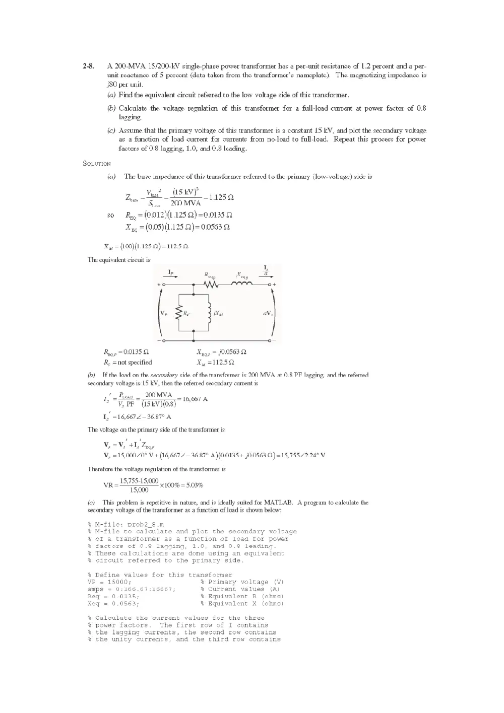
2-8. A 200-MVA 15/200-EV single-phase power transformer has a per-unit resistance of 1.2 percent and a per-
unit reactance of 5 percent (data taken from the transformer’s nameplate), The magnetizing impedance is
J80 per unil.
(a) Find the equivalent circuit referred to the low voltage side of this transformer.
(&) Calculate the voltage regulation of this transformer for a full-load current at power factor of 0.8
lagging.
ic) Assume. that the primary voltage. of this transformer is a constant 15 KV, and plot the secondary vcltage
as a function of load current for currents from no-load to full-load. Repeat this process for power
factors of 0.8 lagging, 1.0, md 0.8 leading.
SoLurion
(a) The base impedance of this transformer referred to the primary (low-voltage) side is
2 (skvy
Zoae Moet MISEYY 5.0
Si. 200 MVA
so Ry = (0.012\(1.125 Q)=0.01335 2
Xyo = (0.05) (1.125 2)= 0.0553 2
X yy = (100)(1.125 Q)= 112.5
The equivalent circuit is
I 1,
iP R x a
Rap = 9.0135 Q Xyggp = J0,0563 Q
R, =not specified Xy =112.52
(b) Tf the load on the secondary side of the transformer is 200 MVA at 0.8 PF lagging, and the referred
secondary voltage is 15 kV, then the referred secondary current is
1 — Plow __200MVA
° "y, PF (15kV)(0.8)
I, =16,6672—36.87° A
= 16,667 A
The voltage on the primary side of the transformer is
yo
V,=V, +1, Zeop
V, =15,000/0° V+ (16, 667—3687° A)(0.0135+ j0.0563.O)=15,755/2.24° V
Therefore the voltage regulation of the transformer is
_ 15,755-15,000
15,000
(c) This problem is repetitive in nature, and is ideally suited for MATLAB. A program to calculate the
secondary voltage of the transformer as a function of load is shown below:
VR X100% = 5.03%
M-file: prob2_8.m
M-file to calculate and plot the secondary voltage
of a transformer as a function of load for power
factors of 0.2 lagging, 1.0, and 0.2 leading.
These calculations are done using an equivalent
circuit referred to the primary side.
oe oe
oe
ee
88 oe
% Define values for this transformer
VP 15000; % Primary voltage (V)
amps = 0:166.67:16667; % Current values (A)
Req = 0.0125; % Equivalent R (ohms)
Xeq = 0.0563; % Equivalent X (ohms)
Calculate the current values for the three
power factors. The first row of I contains
the lagging currents, the second rew contains
the unity currents, and the third row contains
22 20 6°
oe
%® the leading currents
I(1,:) = amps .* ( 0.8 - j*0.6); % Lagging
I(2,:) = amps .* ( 1.0 ); % Unity
I(3,:) = amps .* ( 0.8 + j*0.6); % Leading
% Calculate VS referred to the primary side
% for each current and power factor.
aVS = VP - (Req.*I + j.*Xeq.*I);
% Refer the secondary voltages back to the
%® secondary side using the turns ratio.
VS = aVS * (200/15);
2
%® Plot the secondary voltage (in kV!) versus load
plot (amps,abs(VS(1,:)/1000),'b-','LineWidth',2.0);
hold on;
plot (amps,abs(VS(2,:)/1000),'k--','LineWidth' ,2.0);
plot (amps,abs(VS(3,:)/1000),'r-.','LineWidth' ,2.0);
title ('\bfSecondary Voltage Versus Load');
xlabel ('\bfLoad (A)');
ylabel ('\bfSecondary Voltage (kV)');
legend('0.8 PF lagging','1.0 PF','0.8 PF leading’) ;
grid on;
hold off;
The resulting plot of secondary voltage versus load is shown below:
Secondary Voltage Versus Load
206 T T T T T T
204
202
ix)
Ss
3
198
Secondary Voltage (kV)
©
a
194
192
190 ’
i l i i i
° 2000 4000 6000 8000 10000 12000
Load (A)
i
14000
Ll
16000
18000
2-10.
(a)
A 13,800/480 V three-phase Y-A-connected transformer bank consists of three identical 100-KVA
79G7/480-V tramsfouuers. It is supplied with power directly rom a large coustant-vollage bus. Lo the
short-cirenit test, the recorded valnes on the high-voltage side for one of these transformers are.
Vig = 560 V I,, =12.6A Py. = 3300 W
(a) Tf this hank delivers a rated load at 0.85 PF lagging anc rated voltage, what is the line-to-line voltage on
the primary of the transtormer bank?
(b) Whaat is the veltage regulation uncker these ccrdditions?
(ec) Assume that the primary voltage of this transformer bank is a constant 13.8 kV, and plot the secondary
voltage as a function of load current for currents from no-load to full-load. Repeat this process for
power facters of 0.85 lagging, 1.0, and 0.85 leading.
(@) Plot the voltage regulation of this transformer as a fimction of lead current for currents from no-load to
full load. Repeat this process for power factors of 0.85 lagging, 1.0, and 0.85 leading.
SoLutTion From the short-circuit information, it is possible to determine the per-phase impedance of the
transformer bank referred to the high-voltage side. The primary side of this transformer is Y-ccnnccted, so
the short-circuit phase voliage is
r 56
Vyge = 8 = OY =3233V
3 3
the short-circuit phase current is
Eyeo = tag =12.6A
and the power per phase is
Po.
Py se >: 1100 W
Thus the per phase impedance is
323.3 V9
Zee) =|Ray + JX ge | = ——— = 25.66 2
val =|Roe + Aa 12.6A
{
@=cost Pye = 1100 W =743°
Veolon wee 3V)(12.6 A}
Zan = Reg + aq = 25.66271.3° = 6.914 fU7Q
Rey = 6.94 2
Nig = fATO
If this Y-A transformer bank delivers rated kVA (300 kVA) at 0.85 power factor lagging while the
secondary voltage is at rated value, then each transformer delivers 100 kVA at a voltage of 480 V and 0.85
PF lagging. Referred to the primary side of one of the transformers, the load on each transformer is
equivalent to 100 kVA at 7967 V and 0.85 PF lagging. The equivalent current flowing in the secondary of
one transformer referred to the primary side is
+ 100 kVA
= =1255A
ee 7967 V
9 712.5582 -31.79° A
The voltage on the primary side of a single transformer is thus
Vie =Vys tIys Z
,
98 MEQP
Vy» = 796720" V+ (12.552 —31.79° A)(6.94 + 724.7 Q)=820721.52° V
‘The line-to-line voltage on the primary of the transformer is
Vine = V3 Vp = V3(8207 V)= 14.22 kV
(2) The voltage regulation of the transformer is
_ 8207-7967
7967
100% = 3.01%
Note: It is much easier to solve problems of this sort in the per-unit
stem, as we shall see in the next problem.
(c) This sort of repetitive operation is best performed with MATLAB. A suitable MATLAB program is
shown below:
M-file: prob2_10c.m
M-file to calculate and plot the secondary voltage
of a three-phase Y-delta transformer bank as a
function of load for power factors of 0.85 lagging,
1.0, and 0.85 leading. These calculations are done
using an equivalent circuit referred to the primazy side.
dP AP BP AP BP AP
oe
Define values for this transfcrmer
VL — 13900; % Primary line voltage (V)
VPP = VL / sqrti3); % Primary phase voltage (V)
amps = 0:0.0126:12.6; % Phase current valuss (A)
Reg = 6.94; % Equivalent Ek (ohms)
Meq = 24.7; % Equivalent ¥ (ohms)
Calculate che current values for the three
power factors. The first row of I contains
* the lagging currents, tne seccnd row contains
%& the unity currents, and the third row contains
% the leading currents.
re = 0.85;
im = sin(acos(re));
( -* ( re - j*im); % Lagging
( * (1.0 ); % Unity
( .* ( re + j*im); % Leading
% Calculate secondary phase voltaye referred
% to the primary side for each current and
% power factor.
aVSP = VPP - (Req.¥I + 3. ¥*Xeq.*I);
Refer the secondary phase voltages back to
the secondary side using the turns ratio
Because this is a delta-connected secondary,
this is also the line voltage.
VSP = aVSP * (480/7967);
ae dP 30 8
% Plot the secondary voltage vereus lead
plot (amps,abs(VSP(1,:)),'b-','LineWidth’,2.0);
held on;
plot (amps,abs(VSP(2,-)),'k--','LineWidth',2.0);
plot (amps,abs(VSP(3,:)),'r-.','LineWidth',2.0);
title ('\bfSecondary Voltage Versus Load’);
xlabel ('\bfLoad (A)');
ylabel ('\bfSecondary Voltage (V)');
legend ('0.95 PF lagging','1.0 PP','0.95 PP leading');
grid on;
held off;
The resulting plot is shown below:
Secondary Voltage Versus Load
490 T T T T T
485 ae
0.85 PF lagging
1.0PF
0.85 PF leading
‘Secondary Voltage (V)
470
465
°
(a) This sort of repetitive operation is best performed with MATLAB. A suitable MATLAB program is
shown below:
& M-file: prob2_10d.m
of a three-phase Y-delta transformer bank as a
dP dP dP dP de
ae
Define values for this transformer
VL = 13800;
VPP = VL / sqrt(3);
amps = 0:0.0126:12.6;
Req 6.94;
geq = 24.7;
de dP do
Phase current values
Equivalent R (ohms)
Equivalent X (ohms)
oe ote
Calculate the current values for the three
power factors. The first row of I contains
the lagging currents, the second row contains
the unity currents, and the third row contains
the leading currents.
dP dP dP dP ade
re = 0.85;
im = sin(acos(re));
I(1,:) = amps .* ( re - j*im); % Lagging
I(2,:) = amps .* ( 1.0 ); % Unity
I(3,:) = amps .* ( re + j*im); % Leading
Calculate secondary phase voltage referred
to the primary side for each current and
power factor.
2
3
2
so
2
7
aVSP = VPP - (Req.*I + j.*Xeq.*I);
% Calculate the voltage regulation.
VR = (VPP - abs(aVSP)) ./ abs(aVSP) .* 100;
% Plot the voltage regulation versus load
plot(amps,VR(1,:),'b-','LineWidth',2.0);
hold on;
plot(amps,VR(2,:),'k--','LineWidth',2.0);
plot(amps,VR(3,:),'r-.','LineWidth',2.0);
title ('\bfVoltage Regulation Versus Load’);
xlabel ('\bfLoad (A)');
ylabel ('\bfVoltage Regulation (%)');
M-file to calculate and plot the voltage regulation
function of load for power factors of 0.85 lagging,
1.0, and 0.85 leading. These calculations are done
using an equivalent circuit referred to the primary side.
Primary line voltage (V)
Primary phase voltage (V)
(A)
legend ('0.85 PF lagging','1.0 PF','0.85 PF leading') ;
grid on;
hold off;
The resulting plot is shown below:
Voltage Regulation Versus Load
35 T T T T T T
3h — 0.85 PF lagging 4
--- 1.0 PF
— = 0.85 PF leading
Voltage Regulation (%)
Oo 2 4 6 8 10 12 14
2-11. A 100,000-KVA 230/115-KV A-A three-phase power transformer has a per-init. resistance of 0.02 pn and a
pet-unit reaclanwe of 0.055 pu. The eacilation branch ekments are R, =110 pu and X,, = 20 pu.
(a) Lf this transformer supplies a load of 8) MYA at U.85 PEF lagging, draw the phasor diagram of one
phase of the transformer.
() What is the voltage regulation of the transformer bank under these conditions?
(fc) Sketch the equivalent circuit referred to the low-voltage side of one phase of this transformer.
Calentate. all of the transfermer impedances referred to tha low-voltage side.
SoLur:on
(a) The transformer supplies a load of 80 MVA at 0.85 PF lagging. Therefore, the secondary line
current of the transformer is
S _ 80,000,000 VA
Lig =e = 02 A
*NBV,, V3(115,000 V)
The base value of the secondary line current is
I Sra — _ 100,000,000 VA
ane = eee =“ SO2A
sr F3V ese V3(11S,000V)
30 the per-unit secondary current is
lig _402A
om TOA
I
Leos (0.85) =0.82—-31.8°