
EECE 370 Notes Chahine, Spring 2012
American University of Beirut · Electric Machines and Power Fundamentals · 42 pages

Showing the first 10 of 42 pages. Download the PDF to see all of it.
More EECE 370 files
Show the text of this notes
Draft
Chapter 1: Introduction to Machine Principles
1.1 Electromagnetic field
Magnetic Fields (MF) are mechanisms for energy conversion from one form to another i.e. in
transformers, motors, generators… etc. Four basic principles describe how magnetic fields are used
in these devices:
It is a must to establish a magnetic field before the conversion process
1-
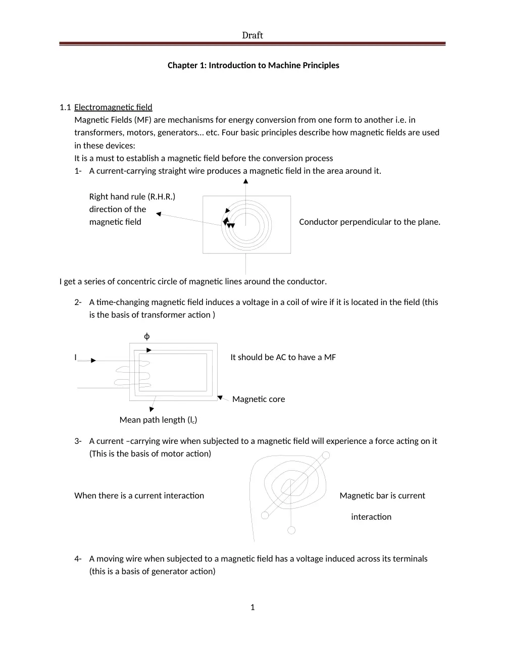
A current-carrying straight wire produces a magnetic field in the area around it.
Right hand rule (R.H.R.)
direction of the
magnetic field Conductor perpendicular to the plane.
I get a series of concentric circle of magnetic lines around the conductor.
2-
A time-changing magnetic field induces a voltage in a coil of wire if it is located in the field (this
is the basis of transformer action )
ф
I It should be AC to have a MF
Magnetic core
Mean path length (lc)
3-
A current –carrying wire when subjected to a magnetic field will experience a force acting on it
(This is the basis of motor action)
When there is a current interaction Magnetic bar is current
interaction
4-
A moving wire when subjected to a magnetic field has a voltage induced across its terminals
(this is a basis of generator action)
1
Draft
1.2 Production of magnetic field:
The basic law governing of Magnetic Field is by Ampere’s law
=Inet
Inet : current (A)
H: magnetic field intensity (Amp.turns/m)
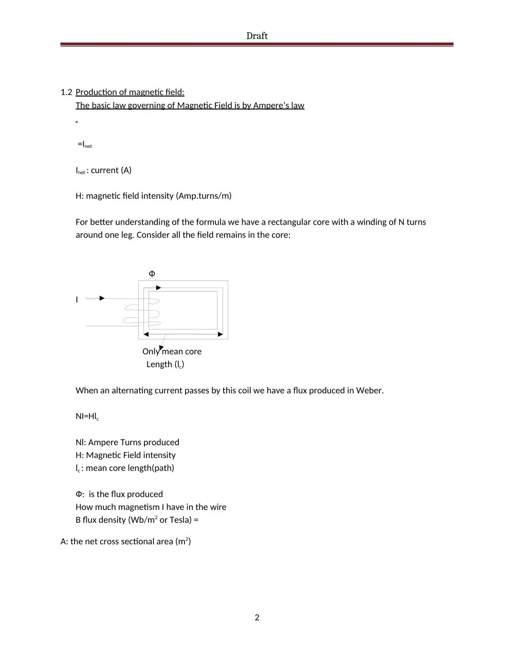
For better understanding of the formula we have a rectangular core with a winding of N turns
around one leg. Consider all the field remains in the core:
Ф
I
Only mean core
Length (lc)
When an alternating current passes by this coil we have a flux produced in Weber.
NI=Hlc
Nl: Ampere Turns produced
H: Magnetic Field intensity
lc : mean core length(path)
Ф: is the flux produced
How much magnetism I have in the wire
B flux density (Wb/m2 or Tesla) =
A: the net cross sectional area (m2)
2
Draft
B=µH
B (Tesla or wb/m2): Flux density
µ: Permeability: the ability of the core medium to be magnetized
H: Magnetic field intensity
µ = µrµ0
µ0= 4π×10-7 H/m (in free air)
for air µr=1.0
µr can reach up to 6000 for certain materials.
B=
Ф= BA=
1.3 Magnetic circuits:
paths for magnetic flux.
1.
Flux lines never intersect
2.
Flux lines follow paths of permeability (least reluctance to magnetism)
3.
Once a loop is established ф is constant in it
I ф
EMF
R
R (reluctance)
V=iR mmf=Ni
mmf = NI
magnetomotive force ф = F/R
permeance = 1/R
3
Draft
Ф = F×P
Ф = µNIA/lc
Ф = F(µA/lc)
R (reluctance AT/wb) = lc/µA for a single medium to be magnetized AT/wb
1.4 Composite magnetic circuits
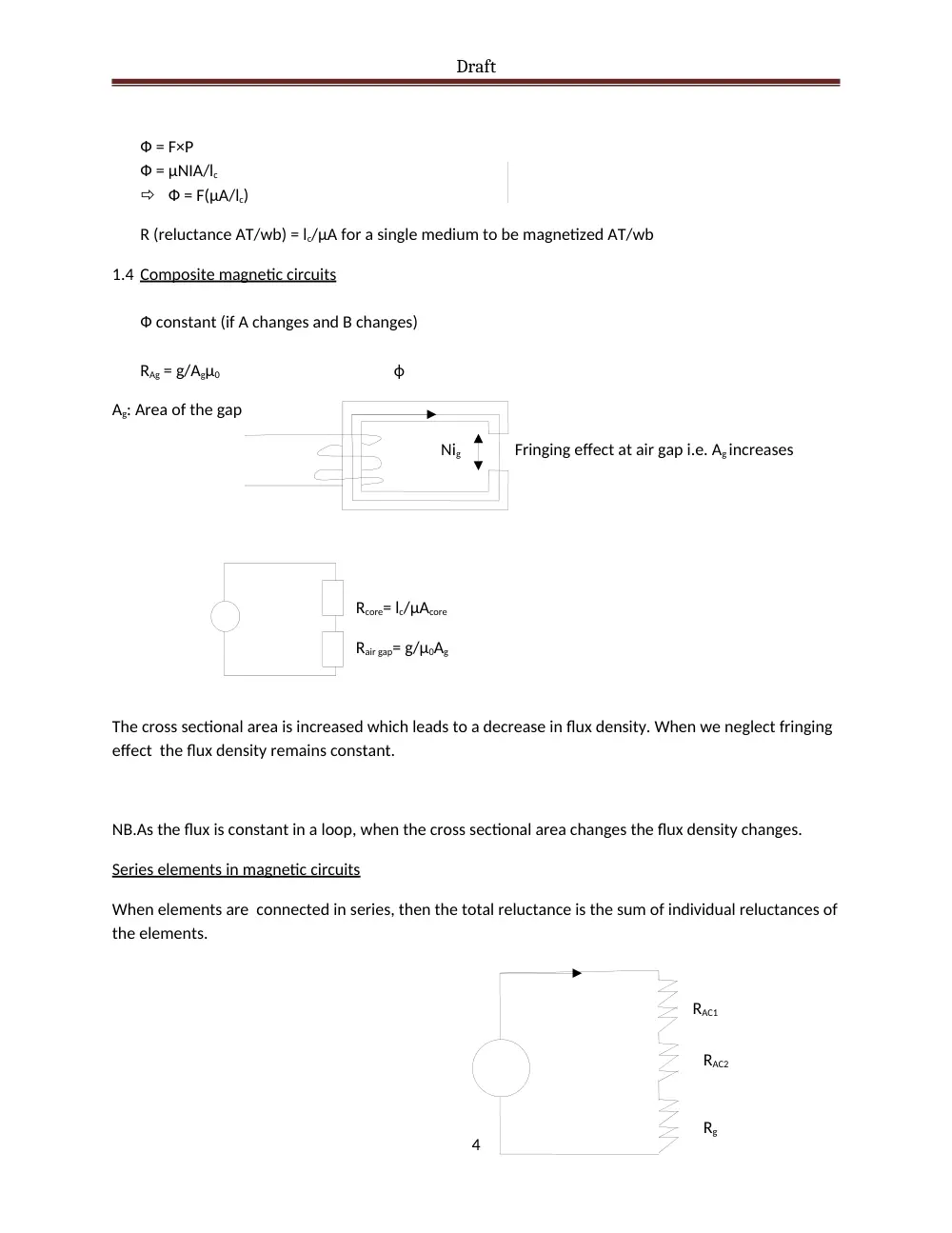
Ф constant (if A changes and B changes)
RAg = g/Agµ0 ф
Ag: Area of the gap
Nig Fringing effect at air gap i.e. Ag increases
Rcore= lc/µAcore
Rair gap= g/µ0Ag
The cross sectional area is increased which leads to a decrease in flux density. When we neglect fringing
effect the flux density remains constant.
NB.As the flux is constant in a loop, when the cross sectional area changes the flux density changes.
Series elements in magnetic circuits
When elements are connected in series, then the total reluctance is the sum of individual reluctances of
the elements.
4
RAC1
RAC2
Rg
Draft
The total reluctance of elements that are in series is equal to the sum of individual reluctances.
NB. B varies when the element area varies.
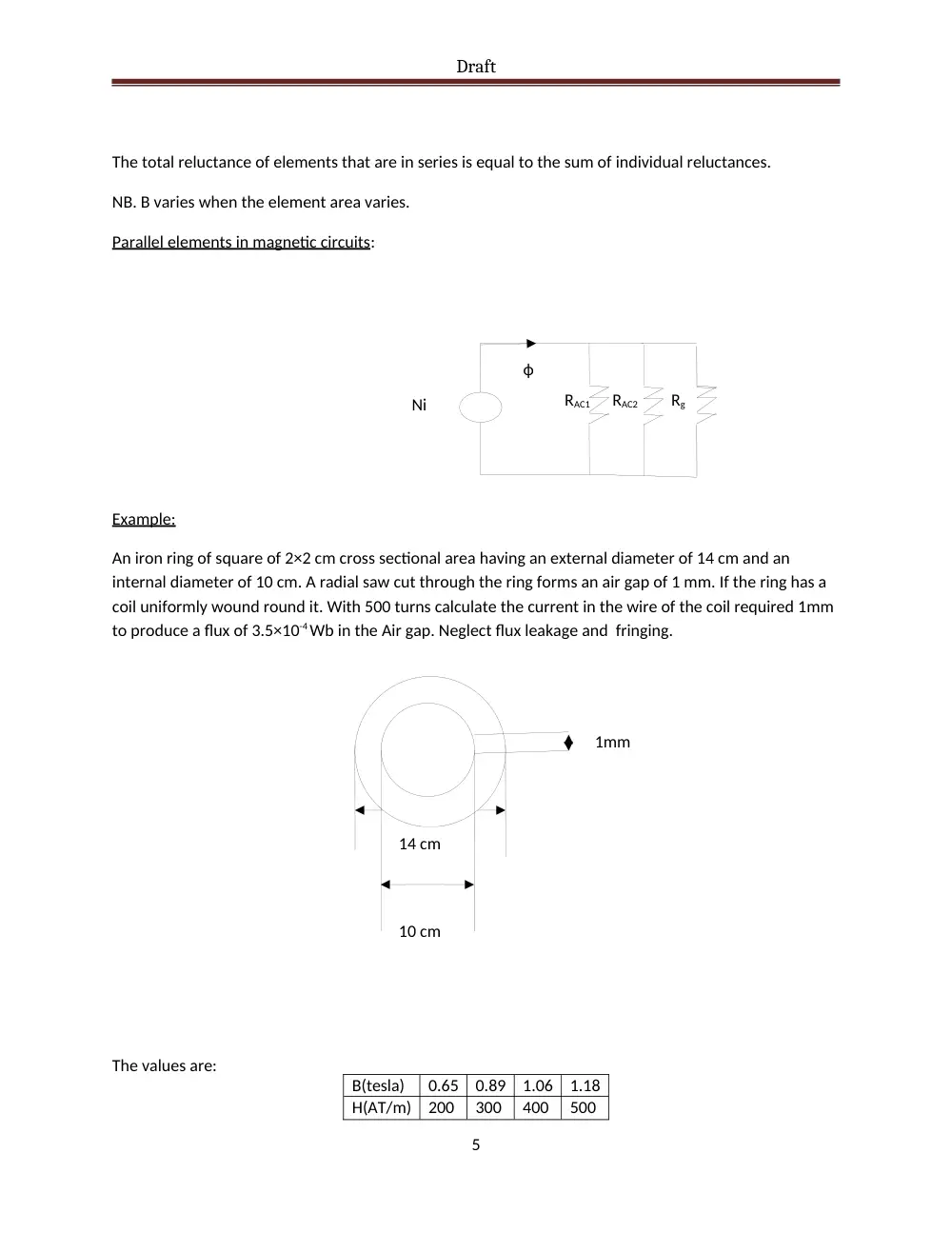
Parallel elements in magnetic circuits:
RAC1 RAC2 Rg
Example:
An iron ring of square of 2×2 cm cross sectional area having an external diameter of 14 cm and an
internal diameter of 10 cm. A radial saw cut through the ring forms an air gap of 1 mm. If the ring has a
coil uniformly wound round it. With 500 turns calculate the current in the wire of the coil required 1mm
to produce a flux of 3.5×10⁻⁴ Wb in the Air gap. Neglect flux leakage and fringing.
The values are:
5
14 cm
10 cm
1mm
ф
Ni
B(tesla)
0.65
0.89
1.06
1.18
H(AT/m)
200
300
400
500
Draft
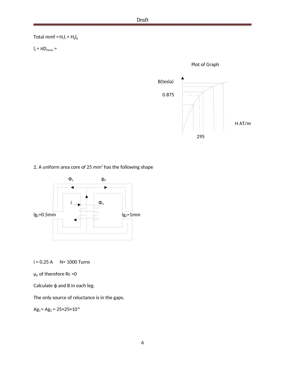
Total mmf = Hclc + Hglg
lc = πDmean =
2. A uniform area core of 25 mm2 has the following shape
Ф1 ф2
i Ф3
lg1=0.5mm lg2=1mm
i = 0.25 A N= 1000 Turns
µp of therefore Rc =0
Calculate ф and B in each leg.
The only source of reluctance is in the gaps.
Ag1 = Ag2 = 25×25×10-6
6
B(tesla)
Plot of Graph
H AT/m
295
0.875
Draft
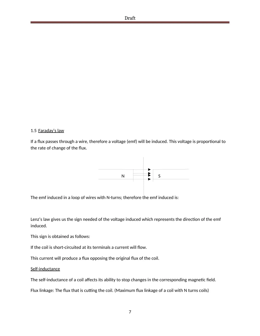
1.5 Faraday’s law
If a flux passes through a wire, therefore a voltage (emf) will be induced. This voltage is proportional to
the rate of change of the flux.
N S
The emf induced in a loop of wires with N-turns; therefore the emf induced is:
Lenz’s law gives us the sign needed of the voltage induced which represents the direction of the emf
induced.
This sign is obtained as follows:
If the coil is short-circuited at its terminals a current will flow.
This current will produce a flux opposing the original flux of the coil.
Self-inductance
The self-inductance of a coil affects its ability to stop changes in the corresponding magnetic field.
Flux linkage: The flux that is cutting the coil. (Maximum flux linkage of a coil with N turns coils)
7
Draft
The energy stored in the magnetic circuit.
Work done equals to energy stored
by replacing
Example:
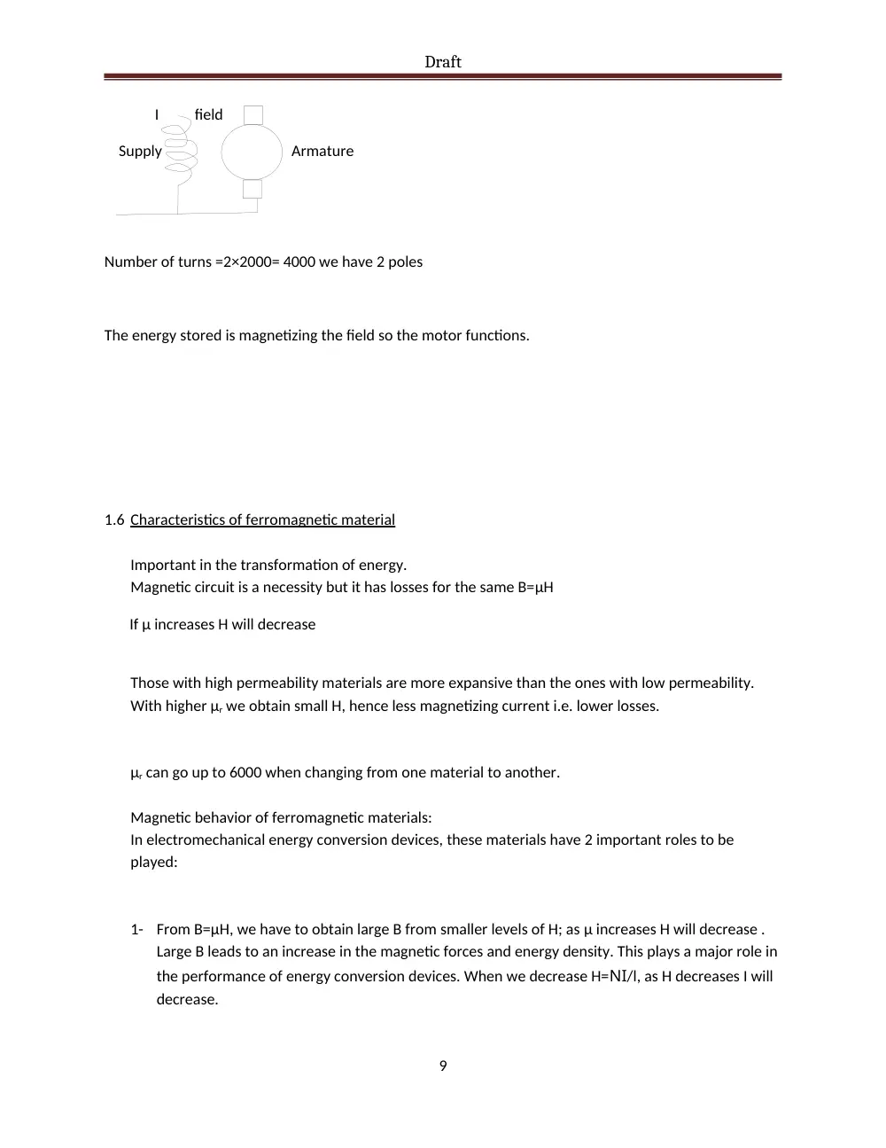
A 2 pole shunt motor has a flux per pole 0.01 Wb when the exciting-current is 2 A the number of turns in
each pole equals 2000. Calculate the energy stored in the magnetic field.
Find L and then ф then the flux linkage.
Ф = 0.01 Wb
8
Draft
I field
Supply Armature
Number of turns =2×2000= 4000 we have 2 poles
The energy stored is magnetizing the field so the motor functions.
1.6 Characteristics of ferromagnetic material
Important in the transformation of energy.
Magnetic circuit is a necessity but it has losses for the same B=µH
If µ increases H will decrease
Those with high permeability materials are more expansive than the ones with low permeability.
With higher µr we obtain small H, hence less magnetizing current i.e. lower losses.
µr can go up to 6000 when changing from one material to another.
Magnetic behavior of ferromagnetic materials:
In electromechanical energy conversion devices, these materials have 2 important roles to be
played:
1-
From B=µH, we have to obtain large B from smaller levels of H; as µ increases H will decrease .
Large B leads to an increase in the magnetic forces and energy density. This plays a major role in
the performance of energy conversion devices. When we decrease H=NI/l, as H decreases I will
decrease.
9
Draft
2-
Magnetic materials can be used to constrain and direct magnetic fields in a well defined path i.e.
in a transformer, it maximize the coupling λ between windings and lower I excitation for
transformer operation. In rotating machines they shape the field to obtain the desired torque
characteristics. Ferronmagnetics are iron, iron alloys with silicon, cobalt, mg, nickel etc…
µ0 is constant; µr varies up to 6000 µ0
saturation
knee
linear
The field is more contained in the magnetic material we have less leakage and better λ and hance
smaller excitation I is needed or lower N (number of turns)
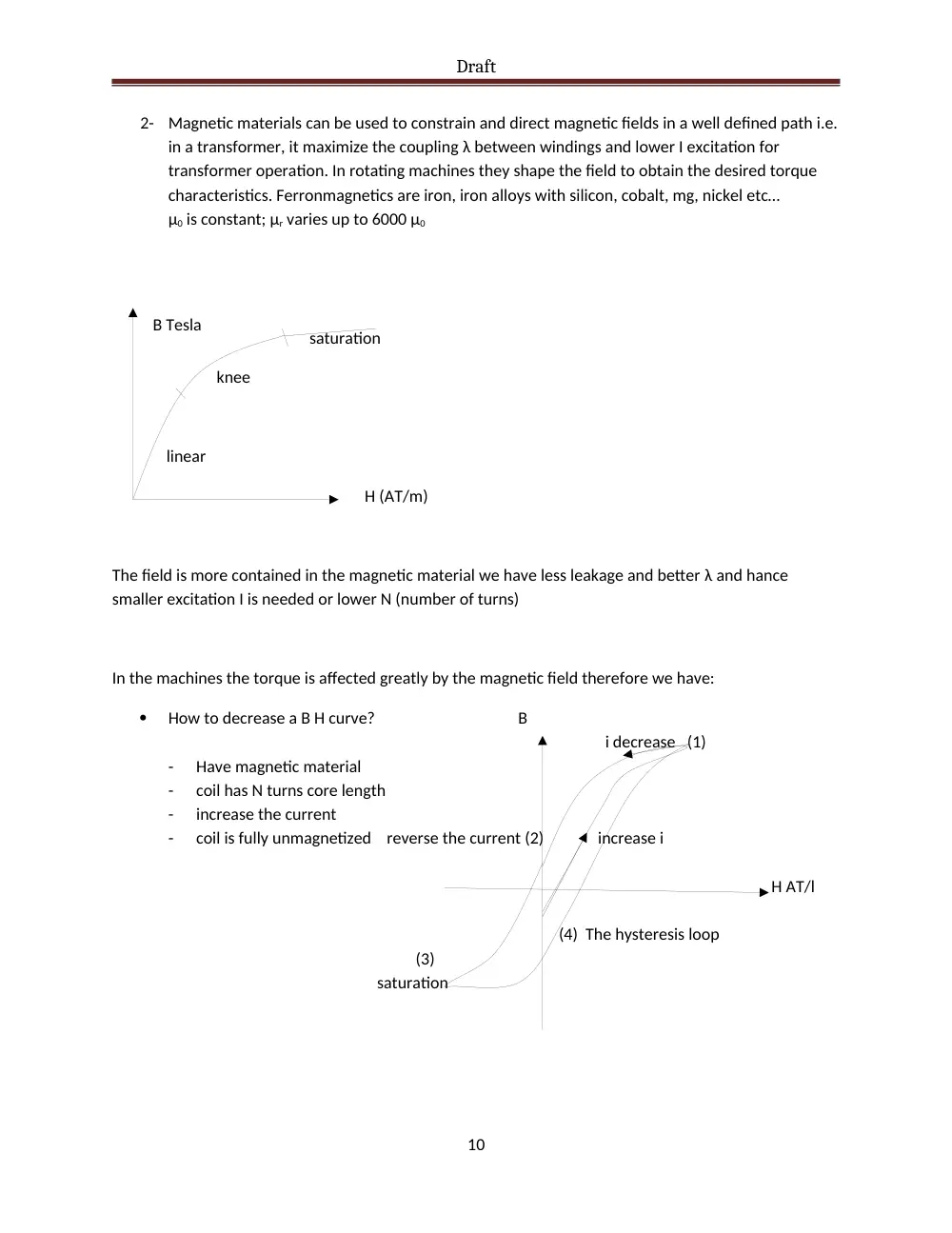
In the machines the torque is affected greatly by the magnetic field therefore we have:
How to decrease a B H curve? B
i decrease (1)
-
Have magnetic material
-
coil has N turns core length
-
increase the current
-
coil is fully unmagnetized reverse the current (2) increase i
H AT/l
(4) The hysteresis loop
(3)
saturation
10
B Tesla
H (AT/m)
Draft
From (1) (2) we start to decrease the current, B doesn’t follow the same path because the
core is magnetized. (Residual flux or magnetism) Then at (2) we reverse the direction of the
current and start increasing it until saturation. It will produce a magnetic field in the opposite
way to (3)
At (3) we start decreasing that current until it reaches 0 value at (4)
At (4) we reverse the current and start increasing it until saturation reaching (1)
The hysteresis loop is the representation of the loss which has to be taken care of. This loss is
due to the formation of flux.
The smaller the hysteresis loop for the material the smaller are the losses hence the better
material.
Flux density varies between 1.5 2.5
For cast-steel flux density= 0.025
The hysterisis losses are proportional to the frequency and not linearly proportional, the ability
of the material to be magnetized.
Pe (eddy current losses) due to emf induced in the core itself which will cause circulating current
in it which results in any current losses
To minimize these losses: of the core increase R by lamination in thin sheets insulation these
sheets from each other then I tight them. Any current losses formula:
V: induced emf
R: Electric resistance of the core
Kl: Constant of material
f: frequency
Bmax: Flux density
A group of e- that has certain magnetic direction form the domain
11
Draft
1.7 Magnetic domains
This happens due to an mmf they are being lined up.
The alignment ends at the saturation, any addition is a waste.
We need the domain to be aligned. Any extra mmf will be a loss.
The hysteresis losses are used to produce theses domains> I want them aligned to produce the
magnetic field.
Ampere-turn is used to align them.
1.8 Motor and generator action due to magnetic field
Motor action:
Assume we have a magnetic field and in the surrounding then it will induce a current-carrying
conductor which will produce a force.
If a current I is flowing B
F (force)
I
L: length of conductor
B: Flux density conductor
N.B. in series magnetic circuit ф is constant; B is not necessarily constant if we have composite circuits
with different cores if we consider fringing A changes.
Generator action:
12
Draft
Induces an emf and then current. V B
Induced voltage in a conductor +++
Moving in a magnetic field
No movement no emf induced L
B: flux density ___
V: velocity of the wire
L: length of the conductor in the magnetic field
The product VB is not constant but we take it as maximum.
Ф is the angle between V and B
Consider ф to be 90°, and their position with respect to the position of the conductor.
Generator action: Its relative mvt between the conductor in a flux density of B(T) with a velocity v.
13
Draft
Chapter 2: Three phase circuits (Ref. appendix A p. 681)
In single phase circuit we have V, I, R, L, C.
In the basic AC single phase
i j𝝎L 1/𝝎C
Hotline H
Neutral N
14
Draft
The instant power is pulsating => circuit is not working efficiently
The effective power is constant
For single phase
P
S Q leading Q lagging
P S
Q: it is released in the magnetic field of inductor as lagging, or in capacitor as leading,.
Electric field to charge a capacitor: current leading.
For the same power when we reduce Q and thus reducing the angle Φ so to the power factor is
improved.
The winding is installed in the magnetic field. When the flux is not cutting the winding, no emf is induced
When the flux is perpendicular to the winding, we have maximum flux cutting it and emf is induced
j𝝎L
15
N
a
a’
S
j𝝎L
R
v(t)
Draft
Z Z’
Z X difference of the two reactances
Ф R (resistance) and X (reactance)
R
, Ф: phase angle and Z: impedance
2.1 Generation of 3-phases
3 coils are Displaced by 120° in space and rotating in a magnetic field
There will be a voltage induced
with an instantaneous value v in each phase.
16
S
a
a’
b
b’
c
c’
N
Draft
°
This is similar to 3 single phase generator producing equal voltages but displaced by 120°
If these conductors are identical (which they normally are) I have three equal voltages induced but
displaced by a 120°.
Phase sequence is the order in which the voltage of each phase reaches its peak value.
vb vc
120 240
I have three currents ia, ib, ic are equal in values but displaced by 120°.
17
va
Draft
When three phases are equally loaded it is called a balanced load.
When we have three single phase loads :
The phases of the loads could be connected in two main ways:
1-
The Y-connection
2-
The Delta-connection
The Y-connection
Wye (star) connected load: this system may also feed a delta connection
18
va
vb
vc
R
R
R
N (neutral)
Draft
The Delta-connection
Va Va Vb
Vc
Vb
Vc
N N
19
Va
Vc
Vb
a
b
c
Draft
If the loads are balanced then the current in the neutral IN =0.
A Y-connected supply Feeding a delta connected load:
We don’t need the neutral for the delta connected load.
It is more advantageous to connect the capacitors in delta to get more reactive power from them.
If I put my voltage meter across the neutral and a line I will get a phase voltage value.
Vф phase voltage
VL line voltage
20
V
V
Draft
Relation between phase voltage and line voltage:
Vф
Vc
VL
120° Va
Vb
Remember the Vф and VL are displaced is WYE
If we have a balanced
load then the phases R
are equally loaded . N R
21
Draft
If the phase angle is N
different it is not R
a balanced load.
For balanced, IN =0;having 3 connections and a neutral instead of 6 between the source and the load.
In the normal case: 3 hotlines and a neutral line.
If balanced we don’t need always the neutral wire.
The line current IL =Iф
For delta-connected
IL1
Ia Ib
Va Vb
Vc Ic IL2
At the point nothing is stored sum of currents is equal to zero
For balanced load: Ic IL
Ia
Ib
As a result the same apply for the other 2 phase currents
22
IL3
Draft
For resistance
S: apparent power
Q: reactive power
If we say power means P unless otherwise said. P in MW, kW, W
ZΔ ZΔ
- ZY
Need to simplify connections
Draw a single line diagram:
The windings are carrying less current.
For pure balanced capacitive load
For the capacitor bank we connect it in delta (use for power compensation)
Ic
P V
ФL Qcomp
23
Draft
S Icomp Q
Scomp
Qc: reactive power drawn by the capacitor
I
V ZL Z
To bring the power factor to less than 1 lagging.
P=constant; as Q decreases, I decreases.
Reduce cross sectional of cable and related conduits ; reduce losses because P is proportional to I2.
P
Qcomp
Example:
24
S
Q
Draft
1
1 0.8
0.9
0.6
Problems
Problem set 1:
1)
4 wire => Y-connected
10Ω
N
25
N
10Ω
10Ω
Draft
Chapter 3: Transformers
3.1 Introduction and EMF equations
3.1.1
Construction
1-
Windings…
2-
Core…
a-
Core form…
b-
Shell…
3-
Tank…
4-
Bushings…
5-
Oil for insulation and cooling…
3.1.2
EMF equations
26
ϕ
Draft
3.2 Principle of operation of Transformer
The voltage at the primary VP produces a current in the windings of the primary IP which
induces a flux ϕ in the core. The direction of ϕ is obtained by the right hand rule. The
flux cuts the primary and the secondary windings producing an induced voltage
EP and ES. If a load is connected across ES a current will flow producing a flux
opposing the main flux and reduces it, which reduces EP and ES. As EP is reduced,
IP is increased as
which brings back instantly the main flux to its original value. i.e. remains
practically constant and hence EP and ES remain at the same value practically.
3.3 Ideal Transformer
1-
No Physterisis or Peddy current losses
2-
No I2R losses (copper losses)
3-
No leakage flux
27
ϕ
Load
VS
Draft
4-
Linear B/H curve and no saturation
3.4 Impedance Transformation
a: ideal transformation ratio
The apparent load impedance on the primary circuit or its effect on the primary circuit.
Example:
A single phase 220/110 V transformer
50 Hz
S=5 kVA
It delivers a secondary current of 20 ampere at 0.8 PF lagging at rated voltage
Assume ideal transformer
28
B
H
Draft
a)
Find
b)
Find referred to the primary side
a)
b)
3.5 Open circuit and Short circuit tests
3.5.1
Open -circuit test
In this test gives, Pcore = Ph +Peddy
Ph: hysteresis losses
Peddy: eddy current losses
Values measured:
29
220V
110V
A
V
VP rated LV
side of
transformer
Watt meter
Draft
3.5.2
Short -circuit test
H.V. side is usually used to get a noticeable voltage i.e. 4% of 220V which is about
9V, while 4% of 11 kV is 440V. (MV/LV power transformers)
We start from zero and increase carefully the voltage of the variac (potentiometer)
until the ammeter reads IFL.
We measure VS/C , IS/C , and PS/C=the full load copper losses.
We fix the total series impedance referred to the primary side.
Resultant:
30
A
V
Variac start
from zero
S/C
VS/C
Req
Xeq
Irated
Watt meter
Draft
3.6 Efficiency
S is the rated apparent Full load power in kVA
X is the fraction of full load of the transformer
Pcore: core losses (no load losses)
PCu: copper losses
A 200kVA single phase transformer has an η of 98% at FL of the max. η occurs at ¾ of FL,
calculate the:
(i)
The core losses
(ii)
The FL copper losses
(iii)
The efficiency at full and half load
Ignore magnetizing current and assume a PF of 0.8 lagging at all loads.
Let the value of the secondary current IS at FL to be I
The η at FL = 98%
31
Draft
As ηmax occurs at ¾ FL; therefore,
(iii)
At half load:
3.7 Equivalent circuits and Phasor diagram
From O/C and S/C tests, we have found the O/C test so we have established Z0, , Ioc and from
them we get :
From the S/C test we found the series impedance ZSE which is expresses as:
Example:
If test on transformer
A 20 kVA, 8000/240V, 60Hz
Transformer parameters to be determined from:
O/C test:
S/C test:
i.e. secondary S/C
32
Draft
Solution:
From S/C:
Equivalent circuit:
O/C T-shaped equivalent circuit:
33
Req
Xeq
VS’
Rcore
XM
VP
IP
IS’
RS’
XS’
VS’
Rcore
XM
VP
RP
XP
Draft
For T-shaped
Phasor Diagram:
Example:
A 20kVA single phase 8kV/277V 50Hz has
RP= 32Ω, XP= 45Ω
RS= 0.05Ω, XS= 0.06Ω
ROC= 250kΩ, XM= 30kΩ
Transformer supplying FL at rated voltage and PF=0.8 lagging
Find
a)
VP referred to the secondary
b)
Voltage regulation at that load
a)
34
VP
IPXP
IPRP
EP
IS’
I’SR’S
E’S
V’S
ϕ
IS’
I0
Draft
3.8 The Per Unit System
3.9 The Auto Transformer
Normal Transformers have usually two windings: one primary and another secondary.
However, the Auto transformer has one winding which is tapped. We either have to lower
or increase the voltage.
35
11 kV
220 kV
220 kV
66 kV
15 kV
Transmission line
66/15 kV
Draft
Current in the coils are related at the terminals by the equations
From equations (1) and (4) we obtain:
And from equations (6) and (3) we obtain:
36
Step down Transformer
Step up Transformer
Draft
When the voltage ratio is 2:1 the Sout is at 50% but a transformer with ratio of 2:3 due to
core cost mainly is large but losses are less in auto transformer.
Example:
A 10kVA, 120/480V transformer used as an auto transformer connecting a 480V load to a
600V supply.
a)
Determine its kVA rating as an auto transformer
b)
Determine its efficiency at FL at PF=0.9 lagging
a)
37
Draft
b)
3.10
3-Phase Transformers
The 3-phase transformers are lighter, smaller, cheaper, and slightly more efficient. They are
concentric with less flux leakage. The high voltage should be insulated by the core. It also
has better leveling between the high voltage and low voltage. The side is connected to the
tank by bushings.
There are 4 main connections of 3-phase transformers:
38
1- Wye -Wye (Y-Y)
Draft
39
Draft
40
3-Delta-Wye (Δ-Y)
4-Delta-Delta (Δ- Δ)
2- Wye-Delta (Y- Δ)
Draft
Remark: For each transformer:
Example
A 3-Φ bank of transformers in a power system is used to step up the voltage of 13.8 kV
3-Φ generator to 138 kV transmission line. The generator rating is 41.5 MVA.
Specify the voltage, current, the MVA rating of each transformer and establish the table of
operating condition for Y-Y, Y-Δ, Δ-Y, Δ-Δ.
7.97
1736
13.83
79.67
173.6
13.83
7.97
1736
13.83
138
100.2
13.83
13.8
1002
13.83
79.67
173.6
13.83
13.8
1002
13.83
138
100.2
13.83
41
Draft
3.11
42