
EECE 370 Notes, Summer 2009
American University of Beirut · Electric Machines and Power Fundamentals · 11 pages


Showing the first 10 of 11 pages. Download the PDF to see all of it.
More EECE 370 files
Show the text of this notes
Three-phase electric power
This article deals with where, how and why "three phase" is used. For
information on the basic mathematics and principles of three phase, see
three-phase.
Three-phase power transformer which is the sole transfer point for electricity to a
suburban shopping mall in Canada. Note the four wires used for the 208Y/120 volt
service: one is for the neutral, and the other three are for the A, B, and C phases.
Three Phase Electric Power Transmission
Three-phase electric power is a common method of electric power
transmission. It is a type of polyphase system mainly used to power motors
and many other devices. A three-phase system uses less conductor material
to transmit electric power than equivalent single-phase, two-phase, or direct-
current systems at the same voltage.
In a three-phase system, three circuit conductors carry three alternating
currents (of the same frequency) which reach their instantaneous peak values
at different times. Taking one conductor as the reference, the other two
currents are delayed in time by one-third and two-thirds of one cycle of the
electrical current. This delay between "phases" has the effect of giving
constant power transfer over each cycle of the current, and also makes it
possible to produce a rotating magnetic field in an electric motor.
Three phase systems may or may not have a neutral wire. A neutral wire
allows the three phase system to use a higher voltage while still supporting
lower voltage single phase appliances. In high voltage distribution situations it
is common not to have a neutral wire as the loads can simply be connected
between phases (phase-phase connection).
Three phase has properties that make it very desirable in electric power
systems. Firstly the phase currents tend to cancel one another (summing to
zero in the case of a linear balanced load). This makes it possible to eliminate
the neutral conductor on some lines; all the phase conductors carry the same
current and so can be the same size, for a balanced load. Secondly power
transfer into a linear balanced load is constant, which helps to reduce
generator and motor vibrations. Finally, three-phase systems can produce a
magnetic field that rotates in a specified direction, which simplifies the design
of electric motors. Three is the lowest phase order to exhibit all of these
properties.
Most domestic loads are single phase. Generally three phase power either
does not enter domestic houses at all, or where it does, it is split out at the
main distribution board.
The three phases are typically indicated by colors which vary by country. See the table for more
information.
Generation and distribution
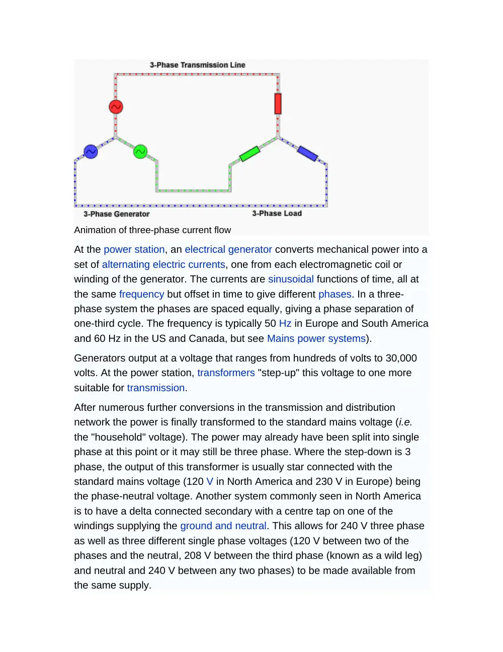
Animation of three-phase current flow
At the power station, an electrical generator converts mechanical power into a
set of alternating electric currents, one from each electromagnetic coil or
winding of the generator. The currents are sinusoidal functions of time, all at
the same frequency but offset in time to give different phases. In a three-
phase system the phases are spaced equally, giving a phase separation of
one-third cycle. The frequency is typically 50 Hz in Europe and South America
and 60 Hz in the US and Canada, but see Mains power systems).
Generators output at a voltage that ranges from hundreds of volts to 30,000
volts. At the power station, transformers "step-up" this voltage to one more
suitable for transmission.
After numerous further conversions in the transmission and distribution
network the power is finally transformed to the standard mains voltage (i.e.
the "household" voltage). The power may already have been split into single
phase at this point or it may still be three phase. Where the step-down is 3
phase, the output of this transformer is usually star connected with the
standard mains voltage (120 V in North America and 230 V in Europe) being
the phase-neutral voltage. Another system commonly seen in North America
is to have a delta connected secondary with a centre tap on one of the
windings supplying the ground and neutral. This allows for 240 V three phase
as well as three different single phase voltages (120 V between two of the
phases and the neutral, 208 V between the third phase (known as a wild leg)
and neutral and 240 V between any two phases) to be made available from
the same supply.
Single-phase loads
Single-phase loads may be connected to a three-phase system, either by
connecting across two live conductors (a phase-to-phase connection), or by
connecting between a phase conductor and the system neutral, which is
either connected to the center of the Y (star) secondary winding of the supply
transformer, or is connected to the center of one winding of a delta
transformer (High leg Delta system) (see transformer and Split phase ).
Single-phase loads should be distributed evenly between the phases of the
three-phase system for efficient use of the supply transformer and supply
conductors.
The line-to-line voltage of a three-phase system is √3 times the line to neutral
voltage. Where the line-to-neutral voltage is a standard utilization voltage, (for
example in a 240 V/415 V system) individual single-phase utility customers or
loads may each be connected to a different phase of the supply. Where the
line-to-neutral voltage is not a common utilization voltage, for example in a
347/600 V system, single-phase loads must be supplied by individual step-
down transformers. In multiple-unit residential buildings in North America,
lighting and convenience outlets can be connected line-to-neutral to give the
120 V distribution voltage (115V utilization voltage), and high-power loads
such as cooking equipment, space heating, water heaters, or air conditioning
can be connected across two phases to give 208 V. This practice is common
enough that 208 V single-phase equipment is readily available in North
America. Attempts to use the more common 120/240 V equipment intended
for three-wire single-phase distribution may result in poor performance since
240 V heating equipment will only produce 75% of its rating when operated at
208 V.
Where three phase at low voltage is otherwise in use, it may still be split out
into single phase service cables through joints in the supply network or it may
be delivered to a master distribution board (breaker panel) at the customer's
premises. Connecting an electrical circuit from one phase to the neutral
generally supplies the country's standard single phase voltage (120 VAC or
230 VAC) to the circuit.
The power transmission grid is organized so that each phase carries the
same magnitude of current out of the major parts of the transmission system.
The currents returning from the customers' premises to the last supply
transformer all share the neutral wire, but the three-phase system ensures
that the sum of the returning currents is approximately zero. The delta wiring
of the primary side of that supply transformer means that no neutral is needed
in the high voltage side of the network.
Three-phase loads
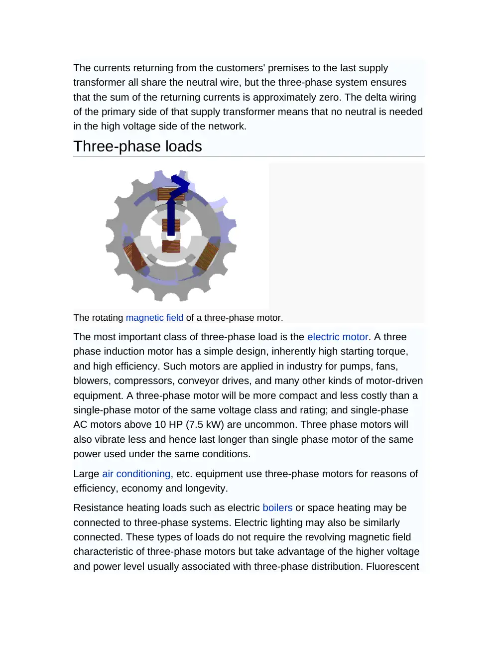
The rotating magnetic field of a three-phase motor.
The most important class of three-phase load is the electric motor. A three
phase induction motor has a simple design, inherently high starting torque,
and high efficiency. Such motors are applied in industry for pumps, fans,
blowers, compressors, conveyor drives, and many other kinds of motor-driven
equipment. A three-phase motor will be more compact and less costly than a
single-phase motor of the same voltage class and rating; and single-phase
AC motors above 10 HP (7.5 kW) are uncommon. Three phase motors will
also vibrate less and hence last longer than single phase motor of the same
power used under the same conditions.
Large air conditioning, etc. equipment use three-phase motors for reasons of
efficiency, economy and longevity.
Resistance heating loads such as electric boilers or space heating may be
connected to three-phase systems. Electric lighting may also be similarly
connected. These types of loads do not require the revolving magnetic field
characteristic of three-phase motors but take advantage of the higher voltage
and power level usually associated with three-phase distribution. Fluorescent
lighting systems also benefit from reduced flicker if adjacent fixtures are
powered from different phases.
Large rectifier systems may have three-phase inputs; the resulting DC current
is easier to filter (smooth) than the output of a single-phase rectifier. Such
rectifiers may be used for battery charging, electrolysis processes such as
aluminum production, or for operation of DC motors.
An interesting example of a three-phase load is the electric arc furnace used
in steelmaking and in refining of ores.
In much of Europe stoves are designed for a three phase feed. Usually the
individual heating units are connected between phase and neutral to allow for
connection to a single phase supply. In many areas of Europe, single phase
power is the only source available.
Phase converters
Occasionally the advantages of three-phase motors make it worthwhile to
convert single-phase power to three phase. Small customers, such as
residential or farm properties may not have access to a three-phase supply,
or may not want to pay for the extra cost of a three-phase service, but may
still wish to use three-phase equipment. Such converters may also allow the
frequency to be varied allowing speed control. Some locomotives are moving
to multi-phase motors driven by such systems even though the incoming
supply to a locomotive is nearly always either DC or single phase AC.
Because single-phase power is interrupted at each moment that the voltage
crosses zero but three-phase delivers power continuously, any such converter
must have a way to store energy for the necessary fraction of a second.
One method for using three-phase equipment on a single-phase supply is
with a rotary phase converter, essentially a three-phase motor with special
starting arrangements and power factor correction that produces balanced
three-phase power. When properly designed these rotary converters can
allow satisfactory operation of three-phase equipment such as machine tools
on a single phase supply. In such a device, the energy storage is performed
by the mechanical inertia (flywheel effect) of the rotating components.
A second method that was popular in the 1940s and 50s was a method that
was called the transformer method. In that time period capacitors were more
expensive relative to transformers. So an autotransformer was used to apply
more power through fewer capacitors. This method performs well and does
have supporters, even today. The usage of the name transformer method
separated it from another common method, the static converter, as both
methods have no moving parts, which separates them from the rotary
converters.
Another method often attempted is with a device referred to as a static phase
converter. This method of running three phase equipment is commonly
attempted with motor loads though it only supplies ⅔ power and can cause
the motor loads to run hot and in some cases overheat. This method will not
work when any circuitry is involved such as CNC devices, or in induction and
rectifier type loads.
Some devices are made which create an imitation three-phase from three-
wire single phase supplies. This is done by creating a third "sub phase"
between the two live conductors, resulting in a phase separation of 180° − 90°
= 90°. Many three-phase devices will run on this configuration, but at lower
efficiency.
Variable-frequency drives (also known as solid-state inverters) are used to
provide precise speed and torque control of three phase motors. Some
models can be powered by a single phase supply. VFDs work by converting
the supply voltage to DC and converting the DC to a suitable three phase
source for the motor.
Alternatives to three-phase
Three-wire single-phase distribution is useful when high voltage three phase
is not available, and allows double the normal utilization voltage to be
supplied for high-power loads.
Two phase power, like three phase, gives constant power transfer to a linear
load. For loads which connect each phase to neutral, assuming the load is the
same power draw, the two wire system has a neutral current which is greater
than neutral current in a three phase system. Also motors aren't entirely
linear, which means that despite the theory, motors running on three phase
tend to run smoother than those on two phase. The generators at Niagara
Falls installed in 1895 were the largest generators in the world at the time and
were two-phase machines. True two-phase power distribution is essentially
obsolete. Special purpose systems may use a two-phase system for control.
Two-phase power may be obtained from a three-phase system using an
arrangement of transformers called a Scott-T transformer.
Monocyclic power was a name for an asymmetrical modified two-phase
power system used by General Electric around 1897 (championed by Charles
Proteus Steinmetz and Elihu Thomson; this usage was reportedly undertaken
to avoid patent legalities). In this system, a generator was wound with a full-
voltage single phase winding intended for lighting loads, and with a small
(usually ¼ of the line voltage) winding which produced a voltage in quadrature
with the main windings. The intention was to use this "power wire" additional
winding to provide starting torque for induction motors, with the main winding
providing power for lighting loads. After the expiration of the Westinghouse
patents on symmetrical two-phase and three-phase power distribution
systems, the monocyclic system fell out of use.
High phase order systems for power transmission have been built and tested.
Such transmission lines use 6 or 12 phases and design practices
characteristic of extra-high voltage transmission lines. High-phase order
transmission lines may allow transfer of more power through a given
transmission line right-of-way without the expense of a HVDC converter at
each end of the line.
Color codes
Conductors of a three phase system are usually identified by a color code, to
allow for balanced loading and to assure the correct phase rotation for
induction motors. Colors used may adhere to International Standard IEC
60446, older standards, or to no standard at all, and may vary even within a single installation.
For example, in the U.S. and Canada, different color codes are used for grounded (earthed) and
un-grounded systems.
L1
L2
L3
Neutral
Ground /
Protective Earth
United States
(common practice1)
Black
Red
Blue
White or
Gray
Green (the ground
wire may be a bare
copper wire)
United States
(alternative practice2)
Brown
Orange
Yellow
Gray or
White
Green
Canada (mandatory)
Red
Black
Blue
White
Green (or bare
copper)
Canada (isolated three-
phase installations)
Orange
Brown
Yellow
White
Green
Europe and many other
countries, including UK
from April 2004 (IEC
60446)
Brown
Black
Grey
Blue
Green/yellow striped4
Older European (IEC
60446, varies by
country6)
Brown
or black
Black or
brown
Black or
brown
Blue
Green/yellow striped5
UK until April 2006,
South Africa, Malaysia
Red
Yellow
Blue
Black
Green/yellow striped
(green on installations
approx. before 1970)
India
Red
Yellow
Blue
Black
Green
Australia and New
Zealand (per AS/NZS
3000:2000 Section 3.8.1)
Red3
White3
(prev.
yellow)
Blue3
Black
[Black or
Light Blue]
Green/yellow striped
(green on very old
installations)
Note 1: Since 1975, the U.S. National Electric Code does not specify coloring
of phase conductors. It is common practice in many regions to identify
120/208Y conductors as Black/Red/Blue. Local regulations may amend the
N.E.C.
Note 2: The U.S. National Electric Code does not specify coloring of phase
conductors. It is common practice in many regions to identify 277/480Y
conductors as Brown/Orange/Yellow. Local practice may amend the N.E.C.
The US N.E.C. rule 517.160 (5) states these colors are to be used for isolated
power systems in health care facilities. Color of conductors does not identify
voltage of a circuit, because there is no formal standard.
Note 3: In Australia and New Zealand, any color is permitted except
green/yellow, green, black, light blue or yellow. Yellow may still be used in
NZ.
Note that in the U.S. a green/yellow striped wire may indicate an isolated
ground [citation needed]. In most countries today, green/yellow striped wire may only
be used for protective earth (safety ground), and may never be unconnected
or used for any other purpose.
Note 4: The international standard green-yellow marking of protective-earth
conductors was introduced to reduce the risk of confusion by color blind
installers. About 7 to 10% of men cannot clearly distinguish between red and
green, which is a particular concern in older schemes were red marks a live
conductor and green marks protective earth (US terminology: safety ground).
Note 5: In Europe there still exist installations with older colors for protective
earth, but since the early 1970s, all new installations use green/yellow
according to IEC 60446.
Note 6: See Paul Cook: Harmonised colors and alphanumeric marking. IEE
Wiring Matters, spring 2006.