
EECE 370 Problems Solution Manual, Fall 2011
American University of Beirut · Electric Machines and Power Fundamentals · 355 pages · with solution

Showing the first 10 of 355 pages. Download the PDF to see all of it.
More EECE 370 files
- Problems PROBLEM SET · Fall 2012ProblemsView
- Problems Power Factor Correction Example · Summer 2011ProblemsView
- Problems On Electromagnetic Circuits · Fall 2011ProblemsView
- Problems Similar to Previous Exams · Fall 2011ProblemsView
- Problems · Spring 2010ProblemsView
- Problems Synchronous Generators · Summer 2007ProblemsView
- Midterm · Summer 2017ExamView
- Lecture Handout 2 · Fall 2016LabView
Show the text of this problems
i
Solutions Manual
to accompany
Chapman
Electric Machinery Fundamentals
Fifth Edition
Stephen J. Chapman
BAE Systems Australia
ii
Solutions Manual to accompany Electric Machinery Fundamentals, Fifth Edition
Copyright 2012 McGraw-Hill, Inc.
All rights reserved. Printed in the United States of America. No part of this book may be used or reproduced in
any manner whatsoever without written permission, with the following exception: homework solutions may be
copied for classroom use.
iii
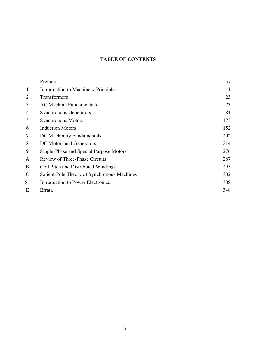
TABLE OF CONTENTS
Preface
iv
1
Introduction to Machinery Principles
1
2
Transformers
23
3
AC Machine Fundamentals
73
4
Synchronous Generators
81
5
Synchronous Motors
123
6
Induction Motors
152
7
DC Machinery Fundamentals
202
8
DC Motors and Generators
214
9
Single-Phase and Special Purpose Motors
276
A
Review of Three-Phase Circuits
287
B
Coil Pitch and Distributed Windings
295
C
Salient-Pole Theory of Synchronous Machines
302
S1
Introduction to Power Electronics
308
E
Errata
348
iv
PREFACE
TO THE INSTRUCTOR
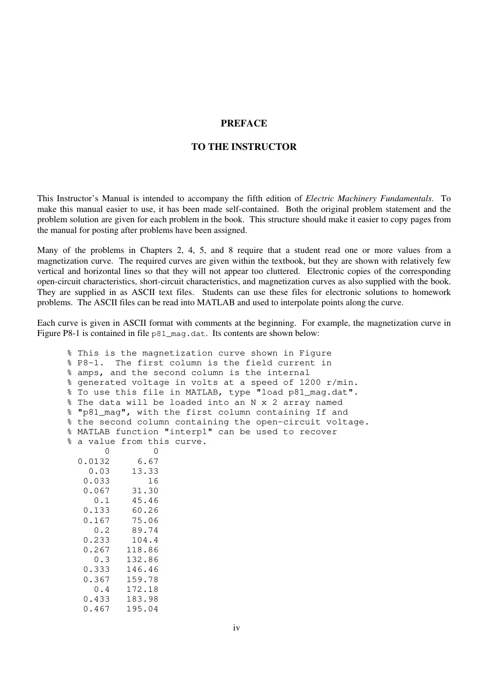
This Instructor’s Manual is intended to accompany the fifth edition of Electric Machinery Fundamentals. To
make this manual easier to use, it has been made self-contained. Both the original problem statement and the
problem solution are given for each problem in the book. This structure should make it easier to copy pages from
the manual for posting after problems have been assigned.
Many of the problems in Chapters 2, 4, 5, and 8 require that a student read one or more values from a
magnetization curve. The required curves are given within the textbook, but they are shown with relatively few
vertical and horizontal lines so that they will not appear too cluttered. Electronic copies of the corresponding
open-circuit characteristics, short-circuit characteristics, and magnetization curves as also supplied with the book.
They are supplied in as ASCII text files. Students can use these files for electronic solutions to homework
problems. The ASCII files can be read into MATLAB and used to interpolate points along the curve.
Each curve is given in ASCII format with comments at the beginning. For example, the magnetization curve in
Figure P8-1 is contained in file p81_mag.dat. Its contents are shown below:
% This is the magnetization curve shown in Figure
% P8-1. The first column is the field current in
% amps, and the second column is the internal
% generated voltage in volts at a speed of 1200 r/min.
% To use this file in MATLAB, type "load p81_mag.dat".
% The data will be loaded into an N x 2 array named
% "p81_mag", with the first column containing If and
% the second column containing the open-circuit voltage.
% MATLAB function "interp1" can be used to recover
% a value from this curve.
0 0
0.0132 6.67
0.03 13.33
0.033 16
0.067 31.30
0.1 45.46
0.133 60.26
0.167 75.06
0.2 89.74
0.233 104.4
0.267 118.86
0.3 132.86
0.333 146.46
0.367 159.78
0.4 172.18
0.433 183.98
0.467 195.04
v
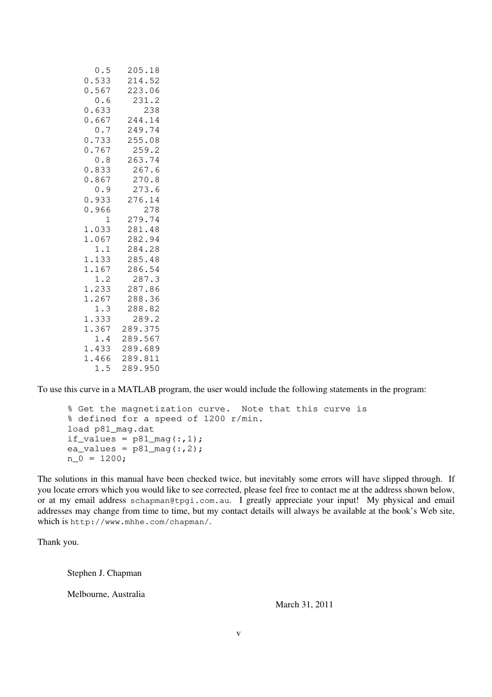
0.5 205.18
0.533 214.52
0.567 223.06
0.6 231.2
0.633 238
0.667 244.14
0.7 249.74
0.733 255.08
0.767 259.2
0.8 263.74
0.833 267.6
0.867 270.8
0.9 273.6
0.933 276.14
0.966 278
1 279.74
1.033 281.48
1.067 282.94
1.1 284.28
1.133 285.48
1.167 286.54
1.2 287.3
1.233 287.86
1.267 288.36
1.3 288.82
1.333 289.2
1.367 289.375
1.4 289.567
1.433 289.689
1.466 289.811
1.5 289.950
To use this curve in a MATLAB program, the user would include the following statements in the program:
% Get the magnetization curve. Note that this curve is
% defined for a speed of 1200 r/min.
load p81_mag.dat
if_values = p81_mag(:,1);
ea_values = p81_mag(:,2);
n_0 = 1200;
The solutions in this manual have been checked twice, but inevitably some errors will have slipped through. If
you locate errors which you would like to see corrected, please feel free to contact me at the address shown below,
or at my email address schapman@tpgi.com.au. I greatly appreciate your input! My physical and email
addresses may change from time to time, but my contact details will always be available at the book’s Web site,
which is http://www.mhhe.com/chapman/.
Thank you.
Stephen J. Chapman
Melbourne, Australia
March 31, 2011
Chapter 1: Introduction to Machinery Principles
1-1.
A motor’s shaft is spinning at a speed of 1800 r/min. What is the shaft speed in radians per second?
SOLUTION The speed in radians per second is
1 min
2 rad
1800 r/min
188.5 rad/s
60 s
1 r
1-2.
A flywheel with a moment of inertia of 4 kg m2 is initially at rest. If a torque of 6 N m
(counterclockwise) is suddenly applied to the flywheel, what will be the speed of the flywheel after 5 s?
Express that speed in both radians per second and revolutions per minute.
SOLUTION The speed in radians per second is:
2
6 N m
5 s
7.5 rad/s
4 kg m
t
t
J
The speed in revolutions per minute is:
1 r
60 s
7.5 rad/s
71.6 r/min
2 rad
1 min
n
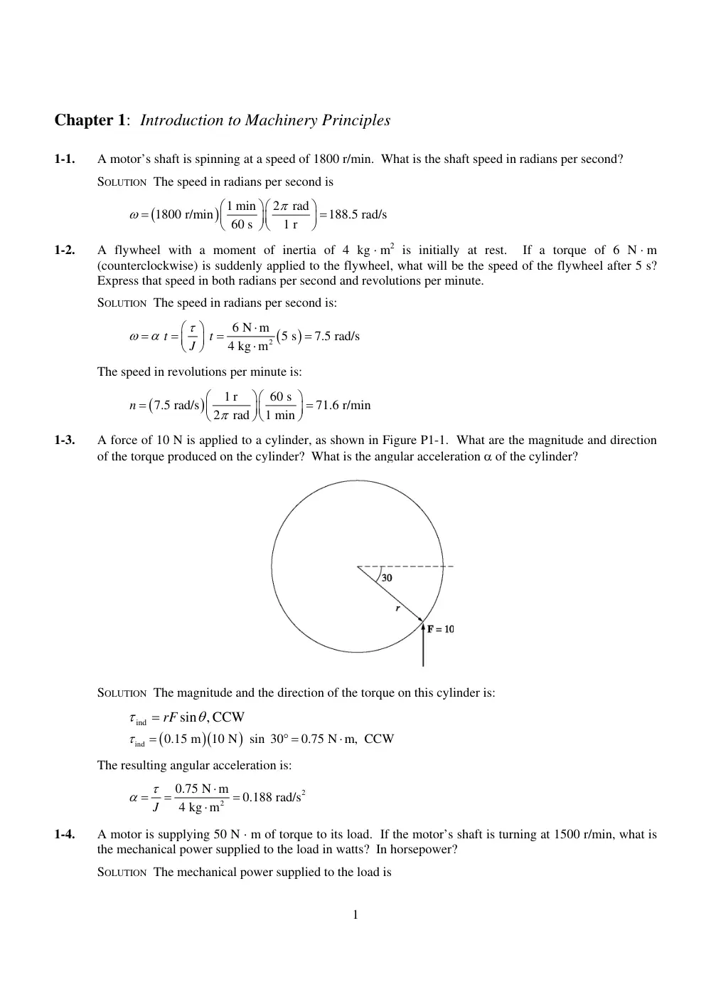
1-3.
A force of 10 N is applied to a cylinder, as shown in Figure P1-1. What are the magnitude and direction
of the torque produced on the cylinder? What is the angular acceleration of the cylinder?
SOLUTION The magnitude and the direction of the torque on this cylinder is:
, CCW
sin
ind
rF
ind
0.15 m 10 N sin 30
0.75 N m, CCW
The resulting angular acceleration is:
2
2
0.75 N m
0.188 rad/s
4 kg m
J
1-4.
A motor is supplying 50 N m of torque to its load. If the motor’s shaft is turning at 1500 r/min, what is
the mechanical power supplied to the load in watts? In horsepower?
SOLUTION The mechanical power supplied to the load is
1
1 min
2 rad
50 N m 1500 r/min
7854 W
60 s
1 r
P
1 hp
7854 W
10.5 hp
746 W
P
1-5.
A ferromagnetic core is shown in Figure P1-2. The depth of the core is 5 cm. The other dimensions of
the core are as shown in the figure. Find the value of the current that will produce a flux of 0.005 Wb.
With this current, what is the flux density at the top of the core? What is the flux density at the right side
of the core? Assume that the relative permeability of the core is 800.
SOLUTION There are three regions in this core. The top and bottom form one region, the left side forms a
second region, and the right side forms a third region. If we assume that the mean path length of the flux
is in the center of each leg of the core, and if we ignore spreading at the corners of the core, then the path
lengths are
= 2(27.5 cm) = 55 cm,
= 30 cm, and
= 30 cm. The reluctances of these regions are:
1l
2l
3l
1
7
0.55 m
72.9 kA t/Wb
800
4
10 H/m
0.05 m
0.15 m
r
o
l
l
A
A
R
2
7
0.30 m
59.7 kA t/Wb
800
4
10 H/m
0.05 m
0.10 m
r
o
l
l
A
A
R
3
7
0.30 m
119.4 kA t/Wb
800
4
10 H/m
0.05 m
0.05 m
r
o
l
l
A
A
R
The total reluctance is thus
TOT
1
2
3
72.9
59.7
119.4
252 kA t/Wb
R
R
R
R
and the magnetomotive force required to produce a flux of 0.005 Wb is
0.005 Wb
252 kA t/Wb
1260 A t
F
R
and the required current is
1260 A t
2.5 A
500 t
i
N
F
The flux density on the top of the core is
2
0.005 Wb
0.67 T
0.15 m
0.05 m
B
A
The flux density on the right side of the core is
0.005 Wb
2.0 T
0.05 m
0.05 m
B
A
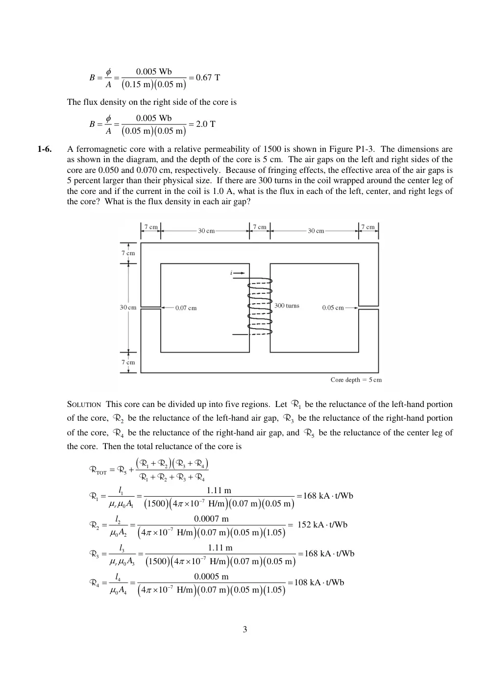
1-6.
A ferromagnetic core with a relative permeability of 1500 is shown in Figure P1-3. The dimensions are
as shown in the diagram, and the depth of the core is 5 cm. The air gaps on the left and right sides of the
core are 0.050 and 0.070 cm, respectively. Because of fringing effects, the effective area of the air gaps is
5 percent larger than their physical size. If there are 300 turns in the coil wrapped around the center leg of
the core and if the current in the coil is 1.0 A, what is the flux in each of the left, center, and right legs of
the core? What is the flux density in each air gap?
SOLUTION This core can be divided up into five regions. Let
be the reluctance of the left-hand portion
of the core,
be the reluctance of the left-hand air gap, R be the reluctance of the right-hand portion
of the core,
be the reluctance of the right-hand air gap, and
be the reluctance of the center leg of
the core. Then the total reluctance of the core is
1
R
3
2
R
R4
5
R
1
2
3
4
TOT
5
1
2
3
4
R
R
R
R
R
R
R
R
R
R
1
1
7
0
1
1.11 m
168 kA t/Wb
1500
4
10 H/m
0.07 m
0.05 m
r
l
A
R
2
2
7
0
2
0.0007 m
152 kA t/Wb
4
10 H/m
0.07 m
0.05 m 1.05
l
A
R
3
3
7
0
3
1.11 m
168 kA t/Wb
1500
4
10 H/m
0.07 m
0.05 m
r
l
A
R
4
4
7
0
4
0.0005 m
108 kA t/Wb
4
10 H/m
0.07 m
0.05 m 1.05
l
A
R
3
5
5
7
0
5
0.37 m
56.1 kA t/Wb
1500
4
10 H/m
0.07 m
0.05 m
r
l
A
R
The total reluctance is
1
2
3
4
TOT
5
1
2
3
4
168
152 168
108
56.1
204 kA t/Wb
168
152
168
108
R
R
R
R
R
R
R
R
R
R
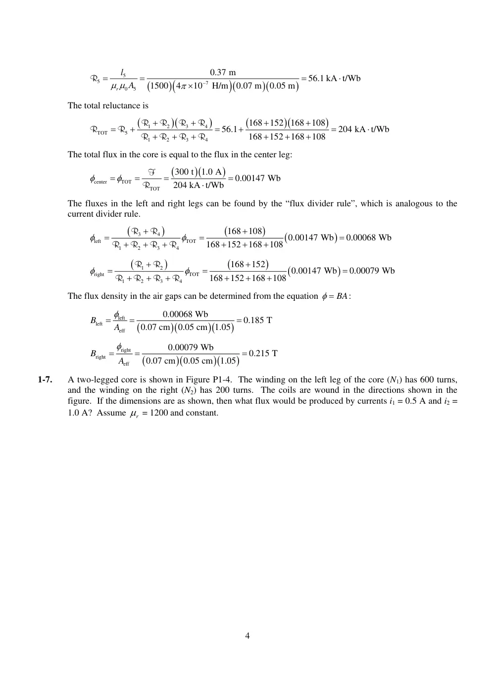
The total flux in the core is equal to the flux in the center leg:
center
TOT
TOT
300 t
1.0 A
0.00147 Wb
204 kA t/Wb
F
R
The fluxes in the left and right legs can be found by the “flux divider rule”, which is analogous to the
current divider rule.
3
4
left
TOT
1
2
3
4
168
108
0.00147 Wb
0.00068 Wb
168
152
168
108
R
R
R
R
R
R
1
2
right
TOT
1
2
3
4
168
152
0.00147 Wb
0.00079 Wb
168
152
168
108
R
R
R
R
R
R
The flux density in the air gaps can be determined from the equation
BA
:
left
left
eff
0.00068 Wb
0.185 T
0.07 cm
0.05 cm 1.05
B
A
right
right
eff
0.00079 Wb
0.215 T
0.07 cm
0.05 cm 1.05
B
A
1-7.
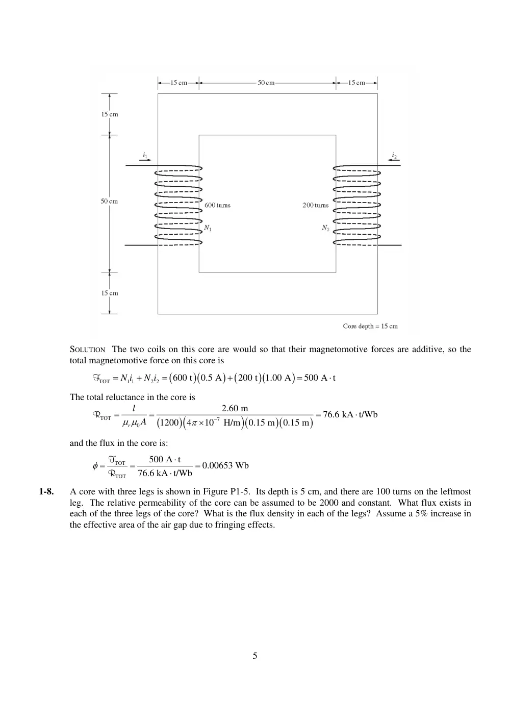
A two-legged core is shown in Figure P1-4. The winding on the left leg of the core (N1) has 600 turns,
and the winding on the right (N2) has 200 turns. The coils are wound in the directions shown in the
figure. If the dimensions are as shown, then what flux would be produced by currents i1 = 0.5 A and i2 =
1.0 A? Assume
r
= 1200 and constant.
4
SOLUTION The two coils on this core are would so that their magnetomotive forces are additive, so the
total magnetomotive force on this core is
TOT
1 1
2 2
600 t
0.5 A
200 t
1.00 A
500 A t
N i
N i
F
The total reluctance in the core is
TOT
7
0
2.60 m
76.6 kA t/Wb
1200
4
10 H/m
0.15 m
0.15 m
r
l
A
R
and the flux in the core is:
TOT
TOT
500 A t
0.00653 Wb
76.6 kA t/Wb
F
R
1-8.
A core with three legs is shown in Figure P1-5. Its depth is 5 cm, and there are 100 turns on the leftmost
leg. The relative permeability of the core can be assumed to be 2000 and constant. What flux exists in
each of the three legs of the core? What is the flux density in each of the legs? Assume a 5% increase in
the effective area of the air gap due to fringing effects.
5
SOLUTION This core can be divided up into four regions. Let
be the reluctance of the left-hand
portion of the core,
be the reluctance of the center leg of the core,
be the reluctance of the center
air gap, and
be the reluctance of the right-hand portion of the core. Then the total reluctance of the
core is the reluctance of the left-hand leg plot the parallel combination of the reluctances of the right-hand
and center legs:
1
R
R2
3
R
4
R
2
3
TOT
1
2
3
R
R
R
R
R
R
R
R
4
4
1
1
7
0
1
1.08 m
95.5 kA t/Wb
2000
4
10 H/m
0.09 m
0.05 m
r
l
A
R
2
2
7
0
2
0.34 m
18.0 kA t/Wb
2000
4
10 H/m
0.15 m
0.05 m
r
l
A
R
3
3
7
0
3
0.0005 m
51.0 kA t/Wb
4
10 H/m
0.15 m
0.05 m 1.04
l
A
R
4
4
7
0
4
1.08 m
95.5 kA t/Wb
2000
4
10 H/m
0.09 m
0.05 m
r
l
A
R
The total reluctance is
2
3
4
TOT
1
2
3
4
18.0
51.0 95.5
95.5
135.5 kA t/Wb
18.0
51.0
95.0
R
R
R
R
R
R
R
R
The total flux in the core is equal to the flux in the left leg:
left
TOT
TOT
100 t
2.0 A
0.00148 Wb
135.5 kA t/Wb
F
R
The fluxes in the center and right legs can be found by the “flux divider rule”, which is analogous to the
current divider rule.
4
center
TOT
2
3
4
95.5
0.00148 Wb
0.00086 Wb
18.0
51.0
95.5
R
R
R
R
6
2
3
right
TOT
2
3
4
18.0
51.0
0.00235 Wb
0.00062 Wb
18.0
51.0
95.5
R
R
R
R
R
The flux density in the legs can be determined from the equation
BA
:
left
left
0.00148 Wb
0.329 T
0.09 m
0.05 m
B
A
center
center
0.00086 Wb
0.115 T
0.15 m
0.05 m
B
A
left
right
0.00062 Wb
0.138 T
0.09 cm
0.05 cm
B
A
1-9.
A wire is shown in Figure P1-6 which is carrying 2.0 A in the presence of a magnetic field. Calculate the
magnitude and direction of the force induced on the wire.
SOLUTION The force on this wire can be calculated from the equation
2 A
1 m
0.5 T
1.00 N, into the page
i
ilB
F
l
B
1-10.
The wire is shown in Figure P1-7 is moving in the presence of a magnetic field. With the information
given in the figure, determine the magnitude and direction of the induced voltage in the wire.
SOLUTION The induced voltage on this wire can be calculated from the equation shown below. The
voltage on the wire is positive downward because the vector quantity
v B
points downward.
7
ind
cos 45
10 m/s
0.2 T
0.25 m cos 45
0.354 V, positive down
e
vBl
v
B
l
1-11.
Repeat Problem 1-10 for the wire in Figure P1-8.
SOLUTION The induced voltage on this wire can be calculated from the equation shown below. The total
voltage is zero, because the vector quantity
v B
points into the page, while the wire runs in the plane of
the page.
ind
cos 90
1 m/s 0.5 T
0.5 m cos 90
0 V
e
vBl
v
B
l
1-12.
The core shown in Figure P1-4 is made of a steel whose magnetization curve is shown in Figure P1-9.
Repeat Problem 1-7, but this time do not assume a constant value of µr. How much flux is produced in
the core by the currents specified? What is the relative permeability of this core under these conditions?
Was the assumption in Problem 1-7 that the relative permeability was equal to 1200 a good assumption
for these conditions? Is it a good assumption in general?
8
SOLUTION The magnetization curve for this core is shown below:
192
9
The two coils on this core are wound so that their magnetomotive forces are additive, so the total
magnetomotive force on this core is
TOT
1 1
2 2
600 t
0.5 A
200 t
1.00 A
500 A t
N i
N i
F
Therefore, the magnetizing intensity H is
500 A t
192 A t/m
2.60 m
c
H
l
F
From the magnetization curve,
0.17 T
B
and the total flux in the core is
TOT
0.17 T
0.15 m
0.15 m
0.00383 Wb
BA
The relative permeability of the core can be found from the reluctance as follows:
A
l
r
0
TOT
TOT
R F
Solving for µr yields
TOT
-7
TOT
0
0.00383 Wb
2.6 m
704
500 A t
4
10 H/m
0.15 m
0.15 m
r
l
A
F
The assumption that
r
= 1200 is not very good here. It is not very good in general.
1-13.
A core with three legs is shown in Figure P1-10. Its depth is 5 cm, and there are 400 turns on the center
leg. The remaining dimensions are shown in the figure. The core is composed of a steel having the
magnetization curve shown in Figure 1-10c. Answer the following questions about this core:
(a) What current is required to produce a flux density of 0.5 T in the central leg of the core?
(b) What current is required to produce a flux density of 1.0 T in the central leg of the core? Is it twice
the current in part (a)?
(c) What are the reluctances of the central and right legs of the core under the conditions in part (a)?
(d) What are the reluctances of the central and right legs of the core under the conditions in part (b)?
(e) What conclusion can you make about reluctances in real magnetic cores?
10
SOLUTION The magnetization curve for this core is shown below:
(a)
A flux density of 0.5 T in the central core corresponds to a total flux of
TOT
0.5 T
0.05 m
0.05 m
0.00125 Wb
BA
By symmetry, the flux in each of the two outer legs must be
1
2
0.000625 Wb
, and the flux density
in the other legs must be
1
2
0.000625 Wb
0.25 T
0.05 m
0.05 m
B
B
The magnetizing intensity H required to produce a flux density of 0.25 T can be found from Figure 1-10c.
It is 50 A·t/m. Similarly, the magnetizing intensity H required to produce a flux density of 0.50 T is 75
A·t/m. The mean length of the center leg is 21 cm and the mean length of each outer leg is 63 dm, so the
total MMF needed is
TOT
center
center
outer
outer
H
l
H
l
F
TOT
75 A t/m
0.21 m
50 A t/m
0.63 m
47.3 A t
F
and the required current is
TOT
47.3 A t
0.12 A
400 t
i
N
F
(b)
A flux density of 1.0 T in the central core corresponds to a total flux of
TOT
1.0 T
0.05 m
0.05 m
0.0025 Wb
BA
By symmetry, the flux in each of the two outer legs must be
1
2
0.00125 Wb
, and the flux density in
the other legs must be
1
2
0.00125 Wb
0.50 T
0.05 m
0.05 m
B
B
11
The magnetizing intensity H required to produce a flux density of 0.50 T can be found from Figure 1-10c.
It is 75 A·t/m. Similarly, the magnetizing intensity H required to produce a flux density of 1.00 T is
about 160 A·t/m. Therefore, the total MMF needed is
TOT
center
center
outer
outer
H
I
H
I
F
TOT
160 A t/m
0.21 m
75 A t/m
0.63 m
80.8 A t
F
and the required current is
TOT
80.8 A t
0.202 A
400 t
i
N
This current is not twice the current in part (a).
(c)
The reluctance of the central leg of the core under the conditions of part (a) is:
TOT
cent
TOT
75 A t/m
0.21 m
12.6 kA t/Wb
0.00125 Wb
F
R
The reluctance of the right leg of the core under the conditions of part (a) is:
TOT
right
TOT
50 A t/m
0.63 m
50.4 kA t/Wb
0.000625 Wb
F
R
(d)
The reluctance of the central leg of the core under the conditions of part (b) is:
TOT
cent
TOT
160 A t/m
0.21 m
13.4 kA t/Wb
0.0025 Wb
F
R
The reluctance of the right leg of the core under the conditions of part (b) is:
TOT
right
TOT
75 A t/m
0.63 m
37.8 kA t/Wb
0.00125 Wb
F
R
(e)
The reluctances in real magnetic cores are not constant.
1-14.
A two-legged magnetic core with an air gap is shown in Figure P1-11. The depth of the core is 5 cm, the
length of the air gap in the core is 0.05 cm, and the number of turns on the coil is 1000. The
magnetization curve of the core material is shown in Figure P1-9. Assume a 5 percent increase in
effective air-gap area to account for fringing. How much current is required to produce an air-gap flux
density of 0.5 T? What are the flux densities of the four sides of the core at that current? What is the total
flux present in the air gap?
12
SOLUTION The magnetization curve for this core is shown below:
An air-gap flux density of 0.5 T requires a total flux of
eff
0.5 T
0.05 m
0.05 m 1.05
0.00131 Wb
BA
This flux requires a flux density in the right-hand leg of
13
right
0.00131 Wb
0.524 T
0.05 m
0.05 m
B
A
The flux density in the other three legs of the core is
top
left
bottom
0.00131 Wb
0.262 T
0.10 m
0.05 m
B
B
B
A
The magnetizing intensity required to produce a flux density of 0.5 T in the air gap can be found from the
equation
ag
ag
o
B
H
:
ag
ag
7
0
0.5 T
398 kA t/m
4
10 H/m
B
H
The magnetizing intensity required to produce a flux density of 0.524 T in the right-hand leg of the core
can be found from Figure P1-9 to be
right
410 A t/m
H
The magnetizing intensity required to produce a flux density of 0.262 T in the top, left, and bottom legs of
the core can be found from Figure P1-9 to be
top
left
bottom
240 A t/m
H
H
H
The total MMF required to produce the flux is
TOT
ag
ag
right
right
top
top
left
left
bottom
bottom
H
l
H
l
H
l
H
l
H
l
F
TOT
398 kA t/m
0.0005 m
410 A t/m
0.40 m
3 240 A t/m
0.40 m
F
TOT
278.6
164
288
651 A t
F
and the required current is
TOT
651 A t
0.651 A
1000 t
i
N
F
The flux densities in the four sides of the core and the total flux present in the air gap were calculated
above.
1-15.
A transformer core with an effective mean path length of 6 in has a 200-turn coil wrapped around one leg.
Its cross-sectional area is 0.25 in2, and its magnetization curve is shown in Figure 1-10c. If current of 0.3
A is flowing in the coil, what is the total flux in the core? What is the flux density?
14
SOLUTION The magnetizing intensity applied to this core is
200 t
0.3 A
394 A t/m
6 in
0.0254 m/in
c
c
Ni
H
l
l
F
From the magnetization curve, the flux density in the core is
B 1.35 T
The total flux in the core is
2
2
0.0254 m
1.35 T
0.25 in
0.000218 Wb
1 in
BA
1-16.
The core shown in Figure P1-2 has the flux shown in Figure P1-12. Sketch the voltage present at the
terminals of the coil.
15
SOLUTION By Lenz’ Law, an increasing flux in the direction shown on the core will produce a voltage that
tends to oppose the increase. This voltage will be the same polarity as the direction shown on the core, so
it will be positive. The induced voltage in the core is given by the equation
ind
d
e
N dt
so the voltage in the windings will be
Time
dt
N d
eind
0 < t < 2 s
500 t 0.010 Wb
2 s
2.50 V
2 < t < 5 s
500 t 0.020 Wb
3 s
-3.33 V
5 < t < 7 s
500 t 0.010 Wb
2 s
2.50 V
7 < t < 8 s
500 t 0.010 Wb
1 s
5.00 V
The resulting voltage is plotted below:
16
1-17.
Figure P1-13 shows the core of a simple dc motor. The magnetization curve for the metal in this core is
given by Figure 1-10c and d. Assume that the cross-sectional area of each air gap is 18 cm2 and that the
width of each air gap is 0.05 cm. The effective diameter of the rotor core is 5 cm.
(a)
We wish to build a machine with as great a flux density as possible while avoiding excessive
saturation in the core. What would be a reasonable maximum flux density for this core?
(b)
What would be the total flux in the core at the flux density of part (a)?
(c)
The maximum possible field current for this machine is 1 A. Select a reasonable number of turns of
wire to provide the desired flux density while not exceeding the maximum available current.
17
SOLUTION The magnetization curve for this core is shown below:
The relative permeability of this core is shown below:
Note: This is a design problem, and the answer presented here is not unique. Other
values could be selected for the flux density in part (a), and other numbers of turns
could be selected in part (c). These other answers are also correct if the proper steps
were followed, and if the choices were reasonable.
(a)
From Figure 1-10c, a reasonable maximum flux density would be about 1.2 T. Notice that the
saturation effects become significant for higher flux densities.
(b)
At a flux density of 1.2 T, the total flux in the core would be
(1.2 T)(0.05 m)(0.05 m)
0.0030 Wb
BA
(c)
The total reluctance of the core is:
18
TOT
stator
air gap 1
rotor
air gap 2
R
R
R
R
R
At a flux density of 1.2 T, the relative permeability
r
of the stator is about 3800, so the stator reluctance
is
stator
stator
7
stator
stator
0.60 m
50.3 kA t/Wb
3800
4
10 H/m
0.05 m
0.05 m
l
A
R
At a flux density of 1.2 T, the relative permeability
r
of the rotor is 3800, so the rotor reluctance is
rotor
rotor
7
stator
rotor
0.05 m
4.2 kA t/Wb
3800
4
10 H/m
0.05 m
0.05 m
l
A
R
The reluctance of both air gap 1 and air gap 2 is
air gap
air gap 1
air gap 2
7
2
air gap
air gap
0.0005 m
221 kA t/Wb
4
10 H/m
0.0018 m
l
A
R
R
Therefore, the total reluctance of the core is
TOT
stator
air gap 1
rotor
air gap 2
R
R
R
R
R
TOT
50.3
221
4.2
221
496 kA t/Wb
R
The required MMF is
TOT
TOT
0.003 Wb
496 kA t/Wb
1488 A t
F
R
Since
F Ni
, and the current is limited to 1 A, one possible choice for the number of turns is N = 2000.
This would allow the desired flux density to be achieved with a current of about 0.74 A.
1-18.
Assume that the voltage applied to a load is
208
30 V
V
and the current flowing through the load
is
2 20 A .
I
(a) Calculate the complex power S consumed by this load.
(b) Is this load inductive or capacitive?
(c) Calculate the power factor of this load?
(d) Calculate the reactive power consumed or supplied by this load. Does the load consume reactive
power from the source or supply it to the source?
SOLUTION
(a)
The complex power S consumed by this load is
*
208
30 V
2 20 A
208
30 V
2
20 A
*
S
VI
416
50 VA
S
(b)
This is a capacitive load.
(c)
The power factor of this load is
PF
cos
50
0.643 leading
(d)
This load supplies reactive power to the source. The reactive power of the load is
sin
208 V
2 A sin
50
319 var
Q
VI
1-19.
Figure P1-14 shows a simple single-phase ac power system with three loads. The voltage source is
240 0 V , impedances of these three loads are
V
1
10 30
Z
2
10 45
Z
3
10
90
Z
19
Answer the following questions about this power system.
(a) Assume that the switch shown in the figure is initially open, and calculate the current I, the power
factor, and the real, reactive, and apparent power being supplied by the source.
(b) How much real, reactive, and apparent power is being consumed by each load with the switch open?
(c) Assume that the switch shown in the figure is now closed, and calculate the current I, the power
factor, and the real, reactive, and apparent power being supplied by the source.
(d) How much real, reactive, and apparent power is being consumed by each load with the switch closed?
(e) What happened to the current flowing from the source when the switch closed? Why?
+
-
I
V
+
-
+
-
+
-
Z1
Z2
3
Z
120 0 V
V
SOLUTION
(a)
With the switch open, only loads 1 and 2 are connected to the source. The current
in Load 1 is
1I
1
240 0 V
24
30 A
10 30 A
I
The current
in Load 2 is
2I
2
240 0 V
24
45 A
10 45 A
I
Therefore the total current from the source is
1
2
24
30 A
24
45 A
47.59
37.5 A
I
I
I
The power factor supplied by the source is
PF
cos
cos 37.5
0.793 lagging
Note that the angle used in the power factor and power calculations is the impedance angle,
which is the negative of the current angle as long as voltage is at 0°.
The real, reactive, and apparent power supplied by the source are
cos
240 V
47.59 A cos 37.5
9061 W
P
VI
cos
240 V
47.59 A sin 37.5
6953 var
Q
VI
240 V
47.59 A
11,420 VA
S
VI
(b)
The real, reactive, and apparent power consumed by Load 1 are
cos
240 V
24 A cos 30
4988 W
P
VI
cos
240 V
24 A sin 30
2880 var
Q
VI
cos
240 V
24 A
5760 VA
S
VI
The real, reactive, and apparent power consumed by Load 2 are
cos
240 V
24 A cos 45
4073 W
P
VI
20
cos
240 V
24 A sin 45
4073 var
Q
VI
cos
240 V
24 A
5760 VA
S
VI
As expected, the real and reactive power supplied by the source are equal to the sum of the
real and reactive powers consumed by the loads.
(c)
With the switch closed, all three loads are connected to the source. The current in Loads 1 and 2 is
the same as before. The current
in Load 3 is
3I
3
240 0 V
24 90 A
10
90 A
I
Therefore the total current from the source is
1
2
3
24
30 A
24
45 A
24 90 A
38.08
7.5 A
I
I
I
I
The power factor supplied by the source is
PF
cos
cos 7.5
0.991 lagging
The real, reactive, and apparent power supplied by the source are
cos
240 V
38.08 A cos 7.5
9061 W
P
VI
cos
240 V
38.08 A sin 7.5
1193 var
Q
VI
240 V
38.08 A
9140 VA
S
VI
(d)
The real, reactive, and apparent power consumed by Load 1 are
cos
240 V
24 A cos 30
4988 W
P
VI
cos
240 V
24 A sin 30
2880 var
Q
VI
cos
240 V
24 A
5760 VA
S
VI
The real, reactive, and apparent power consumed by Load 2 are
cos
240 V
24 A cos 45
4073 W
P
VI
cos
240 V
24 A sin 45
4073 var
Q
VI
cos
240 V
24 A
5760 VA
S
VI
The real, reactive, and apparent power consumed by Load 3 are
cos
240 V
24 A cos
90
0 W
P
VI
cos
240 V
24 A sin
90
5760 var
Q
VI
cos
240 V
24 A
5760 VA
S
VI
As expected, the real and reactive power supplied by the source are equal to the sum of the
real and reactive powers consumed by the loads.
(e)
The current flowing decreased when the switch closed, because most of the reactive power being
consumed by Loads 1 and 2 is being supplied by Load 3. Since less reactive power has to be supplied by
the source, the total current flow decreases.
1-20.
Demonstrate that Equation (1-59) can be derived from Equation (1-58) using simple trigonometric
identities:
( )
( ) ( )
2
cos
cos
p t
v t i t
VI
t
t
(1-58)
( )
cos
1
cos2
sin sin2
p t
VI
t
VI
t
(1-59)
21
SOLUTION
The first step is to apply the following identity:
1
cos
cos
cos
cos
2
The result is
( )
( ) ( )
2
cos
cos
p t
v t i t
VI
t
t
)
1
( )
2
cos
cos
2
p t
VI
t
t
t
t
( )
cos
cos 2
p