
EECE 380 Lecture, Fall 2001
American University of Beirut · Engineering Electromagnetics · 896 pages



Showing the first 10 of 896 pages. Download the PDF to see all of it.
More EECE 380 files
Show the text of this lab
Welcome to the interactive CDROM that accompanies the book
"Fundamentals of Applied Electromagnetics" by Fawwaz T. Ulaby,
Textbook ISBN: 0-13-185089-X, CDROM ISBN: 0-13-145726-8,
copyright Pearson Education, Inc. 2004.
The CD-ROM uses standard HTML with Javascript and
Java for the interactive and animation capabilities.
Make sure these are enabled in your browser preferences.
Many requirements are guidelines and so it is
worth trying your system even if the requirements are not
strictly satisfied.
If you are using a recent browser,
there's a good chance you have all you need to view the CD-ROM.
Below is a table of helper applications used by this CD-ROM.
Visit the sites to get the current versions of each application.
Internet Explorer:
The CD-ROM has been tested on Internet Explorer 5.5
(it should work on others). You can download the current version
by pointing your browser at:
http://www.microsoft.com/windows/ie/default.asp
Acrobat Reader:
The exercises and solved problems are available in pdf
format (as well as gif image format).
You can download the current version
by pointing your browser at:
"http://www.adobe.com/products/acrobat/readstep.html"
Windows requirements:
Pentium-class processor, at least 100 MHz, with 32 MBytes RAM.
The CD has been tested with Windows 98, using Internet
Explorer 5.5.
Unix/Linux requirements:
The system should be no older than about 5 years and have at
least 32 MBytes RAM. Netscape 4.7 has worked on all UNIX systems we
have tried.
Macintosh requirements:
PowerPC processor, at least 100 MHz,
with 32 MBytes RAM. The CD has been tested on a variety of
MAC platforms using Internet Explorer 5.0 and Java version MRJ 2.2.2,
but see "a few more notes", below, for more details.
This CDROM does not install anything on the hard drive.
A few more notes...
Macintosh platform issues
As of this writing (May, 2003) the Macintosh
platform had some troubles worth mentioning here. In particular,
Netscape 4.5 on the Mac will not work with those parts of the CD
that contain Java, notably the animations. This is because the
version of Java supported by Netscape 4.5 is too old. In order for
the animations to work on the Mac you must use Internet Explorer 5.0
or later. You must also install a Java runtime available from
Apple called MRJ 2.2.2,
("http://developer.apple.com/java/text/download.html#software").
since Internet Explorer expects to find it.
Also, make sure that Java is turned on: edit preferences.
Sorry for the trouble.
Font sizes
The files on this CD were designed using a default browser font
of between 14 and 18 points. All of the Greek symbols were made
with that font size in mind. If the Greek symbols look too big
or too small, change your default font size by "editing preferences"
for your browser. Using fonts that are too small or too big may also
cause some formatting problems.
Animations
Sometimes the animations do not work.
There can be several reasons for this, depending on platform.
To fix it, try one of the following two things: (1) Force your browser to
reload the page, rather than using the cache, or (2) kill the
browser and start over.
If this happens repeatedly, you may want to click the "stop
animation" button on every animation before proceeding to
another page.
Contents:
This CDROM contains animations figures, example problems, and
interactive modules as supplemental material for learning the
concepts presented in the accompanying book.
This CD is intended to work on a variety of hardware platforms,
software operating systems, and browsers.
If your software allows networked use of a CDROM reader, then
this CDROM should work in that situation.
Installation and use:
1. Insert the CD into the CD ROM drive.
2. If a window showing the CD contents does not come up,
then you must:
Windows: double-click on "My Computer", then on the CDROM icon
Macintosh: double-click on the CDROM icon.
LINUX: you may need to "mount /dev/cdrom"
and then "ls /cdrom"
3. Now you can start the browser:
Windows/Mac: double-click the "start" icon
LINUX: start up your browser and tell it to load "start.html"
from the CDROM directory.
If the directory window shows the "start" icon you
can probably double-click instead.
Technical support:
If you have problems using this CDROM, email ulaby@umich.edu
and we will try to help.
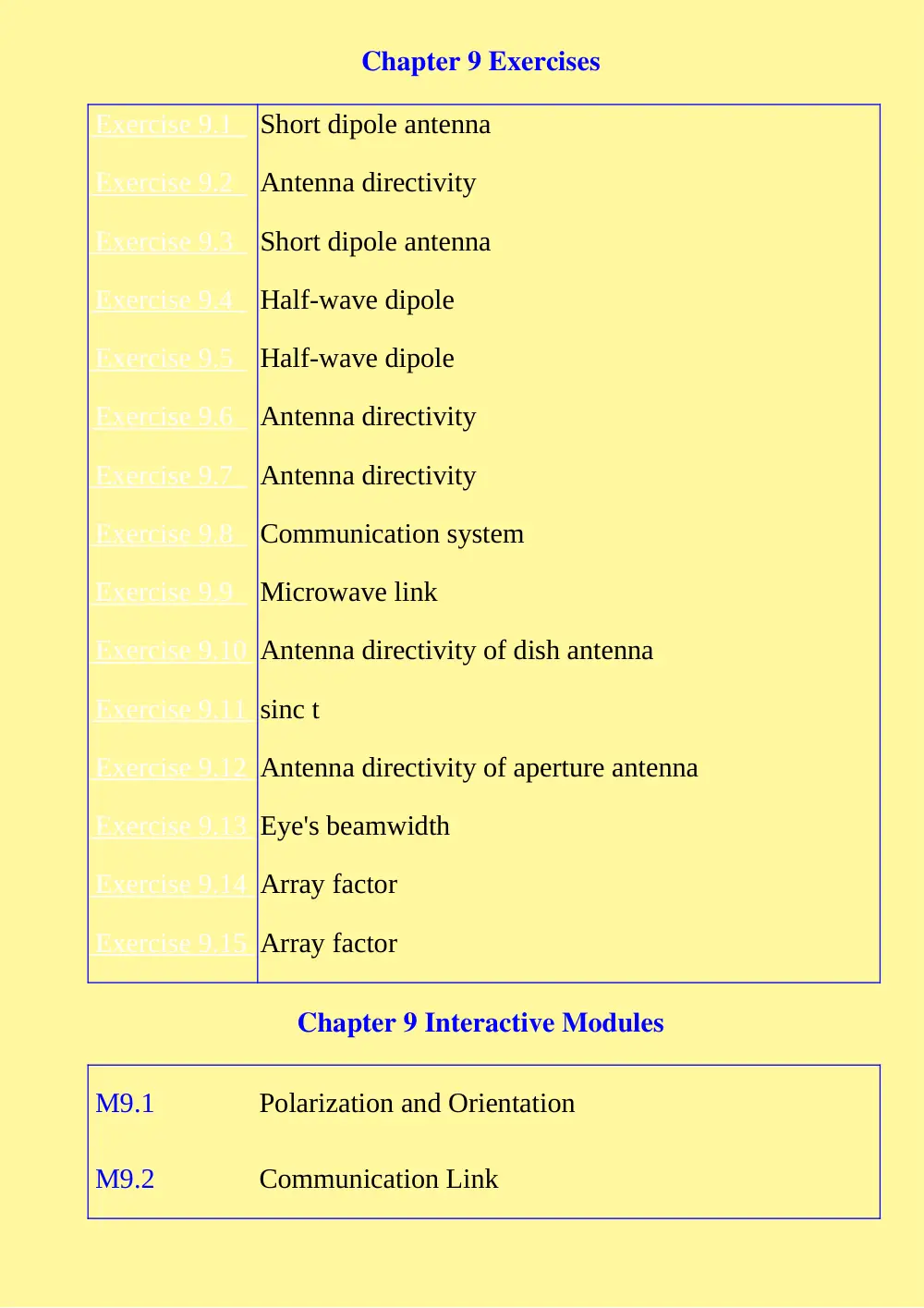
Chapter 9 Exercises
Exercise 9.1
Short dipole antenna
Exercise 9.2
Antenna directivity
Exercise 9.3
Short dipole antenna
Exercise 9.4
Half-wave dipole
Exercise 9.5
Half-wave dipole
Exercise 9.6
Antenna directivity
Exercise 9.7
Antenna directivity
Exercise 9.8
Communication system
Exercise 9.9
Microwave link
Exercise 9.10
Antenna directivity of dish antenna
Exercise 9.11
sinc t
Exercise 9.12
Antenna directivity of aperture antenna
Exercise 9.13
Eye's beamwidth
Exercise 9.14
Array factor
Exercise 9.15
Array factor
Chapter 9 Interactive Modules
M9.1
Polarization and Orientation
M9.2
Communication Link
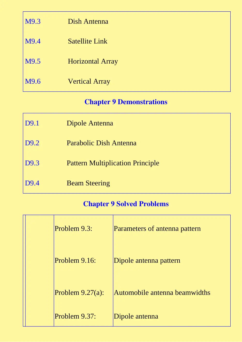
M9.3
Dish Antenna
M9.4
Satellite Link
M9.5
Horizontal Array
M9.6
Vertical Array
Chapter 9 Demonstrations
D9.1
Dipole Antenna
D9.2
Parabolic Dish Antenna
D9.3
Pattern Multiplication Principle
D9.4
Beam Steering
Chapter 9 Solved Problems
Problem 9.3:
Parameters of antenna pattern
Problem 9.16:
Dipole antenna pattern
Problem 9.27(a):
Automobile antenna beamwidths
Problem 9.37:
Dipole antenna
Problem 9.38:
Communication system
Problem 9.39:
Half-wave dipole antenna
Problem 9.40:
Five-element antenna array
Antenna Pattern
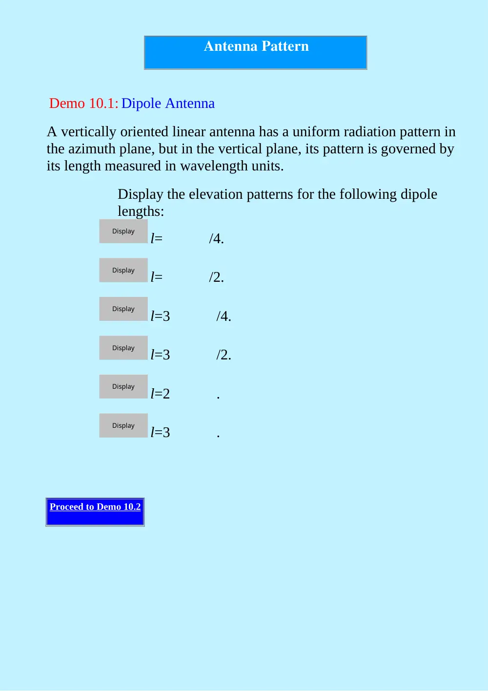
Demo 10.1: Dipole Antenna
A vertically oriented linear antenna has a uniform radiation pattern in
the azimuth plane, but in the vertical plane, its pattern is governed by
its length measured in wavelength units.
Display the elevation patterns for the following dipole
lengths:
l=
/4.
l=
/2.
l=3
/4.
l=3
/2.
l=2
.
l=3
.
Proceed to Demo 10.2
Display
Display
Display
Display
Display
Display
Antenna Pattern
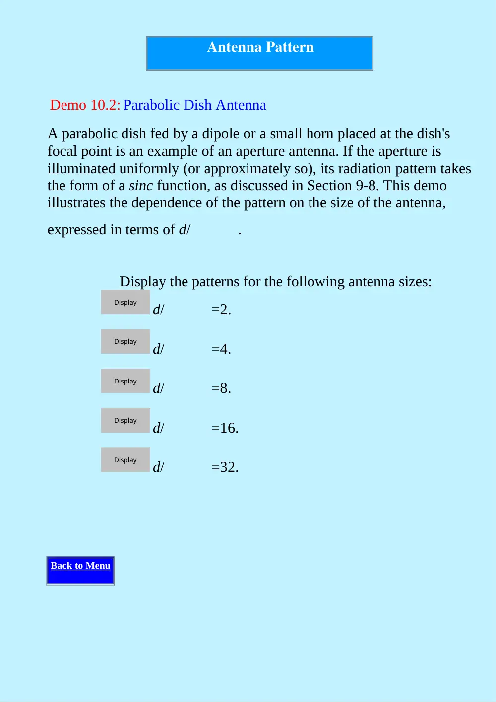
Demo 10.2: Parabolic Dish Antenna
A parabolic dish fed by a dipole or a small horn placed at the dish's
focal point is an example of an aperture antenna. If the aperture is
illuminated uniformly (or approximately so), its radiation pattern takes
the form of a sinc function, as discussed in Section 9-8. This demo
illustrates the dependence of the pattern on the size of the antenna,
expressed in terms of d/
.
Display the patterns for the following antenna sizes:
d/
=2.
d/
=4.
d/
=8.
d/
=16.
d/
=32.
Back to Menu
Display
Display
Display
Display
Display
Chapter 10 Demonstrations
D10.1
Dipole Antenna
D10.2
Parabolic Dish Antenna
Chapter 10 Exercises
Exercise 10.1
Short dipole antenna
Exercise 10.2
Antenna directivity
Exercise 10.3
Short dipole antenna
Exercise 10.4
Half-wave dipole
Exercise 10.5
Half-wave dipole
Exercise 10.6
Antenna directivity
Exercise 10.7
Antenna directivity
Exercise 10.8
Communication system
Exercise 10.9
Microwave link
Exercise
10.10
Antenna directivity of dish antenna
One reason that cell towers might not have been designed with
circularly polarized antennas is because of polarization mismatch: you
are guaranteed not to receive half the tranmitted power when you are
sending a signal from a linearly polarized to a circularly polarized
antenna. In the case of the cell phone itself, that would increase power
consumption and make the whole phone bigger.
The reception would be pretty poor. Although he has oriented his cell-
phone antenna such that the power transmitted towards the base
station is maximized, the polarizations of the transmitting and
receiving antennas are orthogonal to one another. Hence, no signal
would be intercepted.
There would be no reception because both the recieving antenna and transmitting antenna have nulls in
their patterns along the dipole axis. Thus, no signal would be received.
If you try these experiments you may well discover that you do not get
zero reception with different orientations of the phone. This is because
we have not considered the effects of the signal bouncing off the
ground and other surrounding objects (multipath) and the cross
polarization effects that come with that.
Although the use of a circularly polarized antenna on the cell-phone
tower would solve the polarization mismatch problem with a linearly
polarized cell-phone antenna, the cell-phone antenna can intercept no
more than half of the circularly polarized power incident upon it.
Hence, to maintain the same signal level, it would require the tower
antenna to radiate twice as much power as it would with a dipole, and
the same is true for the cell-phone antenna when it operates in a
transmitting mode. Making both antennas circularly polarized
introduces a different set of orientation losses.
Dipole Antenna
Module 10.1: Polarization and Orientation
Given: A cellular phone base station with a vertical dipole antenna at
the top, and a cellular phone user nearby.
Q1. Imagine someone in his backyard pool, talking on the phone
and sunning himself. His cell phone is oriented such that the
antenna is horizontal, as shown in the figure. Is his reception:
Q2. Now consider the same person, who has stood up so that his cell
phone is oriented vertically, and moved his location so that he is
now directly under the base station antenna, as shown in the
figure. Note that the tip of his antenna is pointing directly
towards the tip of the base station antenna. Is his reception:
Q3. Why is it that cell-phone towers do not use circularly polarized
Good
Bad
explain
Good
Bad
explain
antennas?
power consumption/polarization issues
mutual impedance/pattern issues
Proceed to Module 10.2
select
select
explain
Dipole Antenna
Module 10.2: Communication Link
Given: A 300-MHz communication system that utilizes vertically
oriented half-wavelength long dipoles on both the transmitter and
receiver ends of a 10-km link.
Q1. How long are the dipole antennas?
l=
m
Q2. Assuming the transmitter source is a sinusoidal voltage generator with
300 V, and assuming that each dipole is tuned to exhibit an approxima
impedance of 75
, what is the amplitude of the current exiting
dipole antenna?
It0=
A
Q3. What is the average power density of the wave incident upon the recei
antenna?
Si=
W/m2
Q4. What is the corresponding power intercepted by the receiving dipole a
Pint=
nW
Q5. If the receiver circuit is designed to exhibit an equivalent input impeda
, so as to match it to the receiving antenna and the in-between
what is the amplitude of the current flowing through ZL?
check answer
help
I give up
check answer
help
I give up
check answer
help
I give up
check answer
help
I give up
IL0=
A
Proceed to Module 10.3
check answer
help
I give up
Antenna Properties
Module 10.3: Dish Antenna
Given: A parabolic dish antenna of diameter d1 operating at frequency
f1.
Q1. If the antenna is operated at a higher frequency, namely f2=10f1,
how will the antenna beamwidth and directivity change?
(a) Beamwidth will:
Increase by a factor of 10.
Increase by a factor of 100.
Not change.
Decrease by a factor of 10.
Decrease by a factor of 100.
(b) Directivity will:
Increase by a factor of 10.
Increase by a factor of 100.
Not change.
select
select
select
select
select
explain
select
select
select
Decrease by a factor of 10.
Decrease by a factor of 100.
Q2. If the frequency is increased from f1 to f2=10f1 and
simultaneously the antenna is reduced in size to a new diameter
d2=d1/10, what will become of the beamwidth and directivity?
(a) Beamwidth will:
Increase by a factor of 10.
Increase by a factor of 100.
Not change.
Decrease by a factor of 10.
Decrease by a factor of 100.
(b) Directivity will:
Increase by a factor of 10.
Increase by a factor of 100.
Not change.
select
select
explain
select
select
select
select
select
explain
select
select
select
Decrease by a factor of 10.
Decrease by a factor of 100.
Proceed to Module 10.4
select
select
explain
Communication System
Module 10.4: Satellite Link
Given: A 6-GHz satellite to Earth communication link. The satellite, at
40,000 km above Earth's surface, transmits 100 W through a lossless
2-m diameter dish antenna.
Q1. How large in area is the 3-dB footprint of the satellite beam on the sur
Earth?
A=
x105km2
Q2. What is the power intercepted by a small, ground-based, 15 cm diame
antenna pointed toward the satellite?
Pint=
x10-12W
Q3. If the receiver is characterized by a system noise temperature of 100 K
receiver bandwidth is 5 MHz, what is the receiver noise power?
Pn=
x10-15W
Q4. What is the receiver signal-to-noise ratio?
Sn=
dB
Back to Menu
check answer
help
I give up
check answer
help
I give up
check answer
help
I give up
check answer
help
I give up
Chapter 10 Interactive Modules
M10.1
Polarization and Orientation
M10.2
Communication Link
M10.3
Dish Antenna
M10.4
Satellite Link
Chapter 10 Solved Problems
Problem 10.3:
Parameters of antenna pattern
Problem 10.20:
Dipole antenna
Problem 10.21:
Communication system
Problem 10.22:
Half-wave dipole antenna
THIS IS THE MAPPING BETWEEN MakeImages IMAGES AND CH3 MODULES/DEMOS:
source1/img1a.gif --> ~/ch3/demo3.1a.gifsource1/img1b.gif -->
~/ch3/demo3.1b.gifsource1/img2a.gif --> ~/ch3/demo3.2a.gifsource1/img2b.gif
--> ~/ch3/demo3.2b.gifsource1/img3a.gif --> ~/ch3/demo3.3a.gif
source1/img3b.gif --> ~/ch3/demo3.3b.gifsource1/img4a.gif -->
~/ch3/demo3.5a.gifsource1/img4b.gif --> ~/ch3/demo3.5b.gifsource1/img5a.gif
--> ~/ch3/demo3.6a.gifsource1/img5b.gif --> ~/ch3/demo3.6b.gif
source1/img6a.gif --> ~/ch3/demo3.8a.gifsource1/img6b.gif -->
~/ch3/demo3.8b.gifsource1/img7a.gif --> ~/ch3/demo3.7a.gifsource1/img7b.gif
--> ~/ch3/demo3.7b.gifsource1/img8a.gif --> ~/ch3/demo3.9a.gif
source1/img8b.gif --> ~/ch3/demo3.9b.gifsource1/img9a.gif -->
~/ch3/demo3.4a.gifsource1/img9b.gif --> ~/ch3/demo3.4b.gifsource2/img1a.gif
--> ~/ch3/demo3.10b.gifsource2/img1b.gif --> ~/ch3/demo3.10a.gif
source2/img2a.gif --> NOT USEDsource2/img2b.gif --> NOT USED
source2/img3a.gif --> ~/ch3/demo3.11b.gifsource2/img3b.gif -->
~/ch3/demo3.11a.gifsource2/img4a.gif --> ~/ch3/demo3.14b.gifsource2/img4b.gif
--> ~/ch3/demo3.14a.gifsource2/img5a.gif --> ~/ch3/demo3.15b.gif
source2/img5b.gif --> ~/ch3/demo3.15a.gifsource2/img6a.gif -->
~/ch3/mod3.7b.gifsource2/img6b.gif --> ~/ch3/mod3.7a.gifsource2/img7a.gif
--> ~/ch3/mod3.10b.gifsource2/img7b.gif --> ~/ch3/mod3.10a.gif
source2/img8a.gif --> ~/ch3/mod3.9b.gifsource2/img8b.gif -->
~/ch3/mod3.9a.gifsource2/img9a.gif --> ~/ch3/mod3.8b.gifsource2/img9b.gif
--> ~/ch3/mod3.8a.gifsource2/img10a.gif --> ~/ch3/mod3.11b.gif
source2/img10b.gif --> ~/ch3/mod3.11a.gifsource2/img11a.gif -->
~/ch3/demo3.12b.gifsource2/img11b.gif --> ~/ch3/demo3.12a.gif
source2/img12a.gif --> ~/ch3/demo3.13b.gifsource2/img12b.gif -->
~/ch3/demo3.13a.gif
Chapter 3 Exercises
Exercise 3.1
Distance vector
Exercise 3.2
Vector algebra
Exercise 3.3
Vector algebra
Exercise 3.4
Cylinder volume
Exercise 3.5
Coordinate transformation
Exercise 3.6
Coordinate transformation
Exercise 3.7
Gradient
Exercise 3.8
Directional derivative
Exercise 3.9
Divergence in cartesian cooordinates
Exercise 3.10
Divergence in cylindrical cooordinates
Exercise 3.11
Flux through a surface
Exercise 3.12
Divergence theorem
Exercise 3.13
Curl in cylindrical coordinates
Exercise 3.14
Curl in spherical coordinates
Chapter 3 Interactive Modules
M3.1
Two Parallel Vectors
M3.2
Two Intersecting Vectors
M3.3
Intersecting Vectors 2
M3.4
Dot Product
M3.5
Shining Star
M3.6
Sea-Land Temperature Profile
M3.7
Divergence of
M3.8
Divergence of
M3.9
Divergence of
M3.10
Divergence of
M3.11
Divergence of
Chapter 3 Demonstrations
Gradient of Scalar Fields
D3.1
D3.2
D3.3
D3.4
D3.5
D3.6
D3.7
D3.8
D3.9
Divergence of Vector Fields
D3.10
D3.11
D3.12
D3.13
D3.14
D3.15
Chapter 3 Solved Problems
Problem 3.9:
Unit vector
Problem
3.17(b,e):
Sketching vector fields
Problem 3.19(a):
Converting coordinates from
cartesian to cylindrical and
spherical
Problem 3.21(b): Converting coordinates from
spherical to cylindrical
Problem 3.22(d): Surface area
Problem 3.31(c):
Transform vectors to spherical
coordinates
Problem 3.32(d): Calculating the gradient
Problem 3.41:
Verify the divergence theorem
Problem 3.45:
Verify Stokes's theorem
Problem 3.50:
Vector algebra
Problem 3.51:
Vector algebra
Problem 3.52:
Vector orthogonality
Problem 3.53:
Vector transformation
Problem 3.54:
Line integral
Problem 3.55:
Stokes's theorem
Problem 3.56:
Laplacian
Gradient of Scalar Fields
Demo 3.1: Gradient of Scalar Fields
Given: A scalar field defined by:
The field T is displayed graphically in the figure, wherein the
brightness of the image at a given location is proportional to the
magnitude of T at that location.
the graphical and analytical solution for
T
Proceed to Demo 3.2
Display
Divergence of Vector
Fields
Demo 3.10: Divergence of Vector Fields
Given: A vector field defined by:
The vector A is displayed graphically in the figure, wherein vectors
are used to depict the direction and magnitude of A at any given
location.
the graphical and analytical solution for
. A
Proceed to Demo 3.11
Display
Divergence of Vector
Fields
Demo 3.11: Divergence of Vector Fields
Given: A vector field defined by:
The vector A is displayed graphically in the figure, wherein vectors
are used to depict the direction and magnitude of A at any given
location.
the graphical and analytical solution for
. A
Proceed to Demo 3.12
Display
Divergence of Vector
Fields
Demo 3.12: Divergence of Vector Fields
Given: A vector field defined by:
The vector A is displayed graphically in the figure, wherein vectors
are used to depict the direction and magnitude of A at any given
location.
the graphical and analytical solution for
. A
Proceed to Demo 3.13
Display
Divergence of Vector
Fields
Demo 3.13: Divergence of Vector Fields
Given: A vector field defined by:
The vector A is displayed graphically in the figure, wherein vectors
are used to depict the direction and magnitude of A at any given
location.
the graphical and analytical solution for
. A
Proceed to Demo 3.14
Display
Divergence of Vector
Fields
Demo 3.14: Divergence of Vector Fields
Given: A vector field defined by:
The vector A is displayed graphically in the figure, wherein vectors
are used to depict the direction and magnitude of A at any given
location.
the graphical and analytical solution for
. A
Proceed to Demo 3.15
Display
Divergence of Vector
Fields
Demo 3.15: Divergence of Vector Fields
Given: A vector field defined by:
The vector A is displayed graphically in the figure, wherein vectors
are used to depict the direction and magnitude of A at any given
location.
the graphical and analytical solution for
. A
Back to Menu
Display
Gradient of Scalar Fields
Demo 3.2: Gradient of Scalar Fields
Given: A scalar field defined by:
The field T is displayed graphically in the figure, wherein the
brightness of the image at a given location is proportional to the
magnitude of T at that location.
the graphical and analytical solution for
T
Proceed to Demo 3.3
Display
Gradient of Scalar Fields
Demo 3.3: Gradient of Scalar Fields
Given: A scalar field defined by:
The field T is displayed graphically in the figure, wherein the
brightness of the image at a given location is proportional to the
magnitude of T at that location.
the graphical and analytical solution for
T
Proceed to Demo 3.4
Display
Gradient of Scalar Fields
Demo 3.4: Gradient of Scalar Fields
Given: A scalar field defined by:
The field T is displayed graphically in the figure, wherein the
brightness of the image at a given location is proportional to the
magnitude of T at that location.
the graphical and analytical solution for
T
Proceed to Demo 3.5
Display
Gradient of Scalar Fields
Demo 3.5: Gradient of Scalar Fields
Given: A scalar field defined by:
The field T is displayed graphically in the figure, wherein the
brightness of the image at a given location is proportional to the
magnitude of T at that location.
the graphical and analytical solution for
T
Proceed to Demo 3.6
Display
Gradient of Scalar Fields
Demo 3.6: Gradient of Scalar Fields
Given: A scalar field defined by:
The field T is displayed graphically in the figure, wherein the
brightness of the image at a given location is proportional to the
magnitude of T at that location.
the graphical and analytical solution for
T
Proceed to Demo 3.7
Display
Gradient of Scalar Fields
Demo 3.7 Gradient of Scalar Fields
Given: A scalar field defined by:
The field T is displayed graphically in the figure, wherein the
brightness of the image at a given location is proportional to the
magnitude of T at that location.
the graphical and analytical solution for
T
Proceed to Demo 3.8
Display