
EECE 380 Lecture, Fall 2003
American University of Beirut · Engineering Electromagnetics · 2 pages

More EECE 380 files
Show the text of this lab
102
TECHNOLOGY BRIEF: CAPACITIVE SENSORS
Capacitive Sensors
To sense is to respond to a stimulus. (See
Resistive Sensors.) A capacitor can function as
a sensor if the stimulus changes the capacitor’s
geometry — usually the spacing between its
conductive elements — or the dielectric properties
of the insulating material situated between them.
Capacitive sensors are used in a multitude of
applications. A few examples follow.
Fluid Gauge
The two metal electrodes in (A), usually rods or
plates, form a capacitor whose capacitance is di-
rectly proportional to the permittivity of the material
between them. If the fluid section is of height Hf and
A. Fluid tank
Air
To capacitive bridge circuit
C2
Fluid
Tank
d
H − Hf
Hf
the height of the empty space above it is (H − Hf ),
then the overall capacitance is equivalent to two ca-
pacitors in parallel, or
C2 = Cf + Ca = εf
(wHf )
d
+ εa
(H − Hf
d
,
where w is the electrode plate width, d is the
spacing between electrodes, and εf and εa are the
permittivities of the fluid and air, respectively. Rear-
ranging the expression as a linear equation yields
C2 = kHf + C0,
where the constant k = (εf − εa)w/d and C0 is the
capacitance of the tank when totally empty. Using
the linear equation, the fluid height can be deter-
mined by measuring C2, which can be realized by
using a bridge circuit (B). The output voltage Vout is
proportional to the deviation between C1 and C2. By
setting C1 = C0 (a fixed capacitor) and by connect-
ing the tank electrodes to the bridge circuit to form
C2, Vout becomes proportional to the fluid height.
Vg
Vout
+
−
C1
C2
R
R
+
−
B. Bridge circuit with 150 kHz ac source
TECHNOLOGY BRIEF: CAPACITIVE SENSORS
103
Silicon substrate
Electrodes
C. Interdigital capacitor
Humidity Sensor
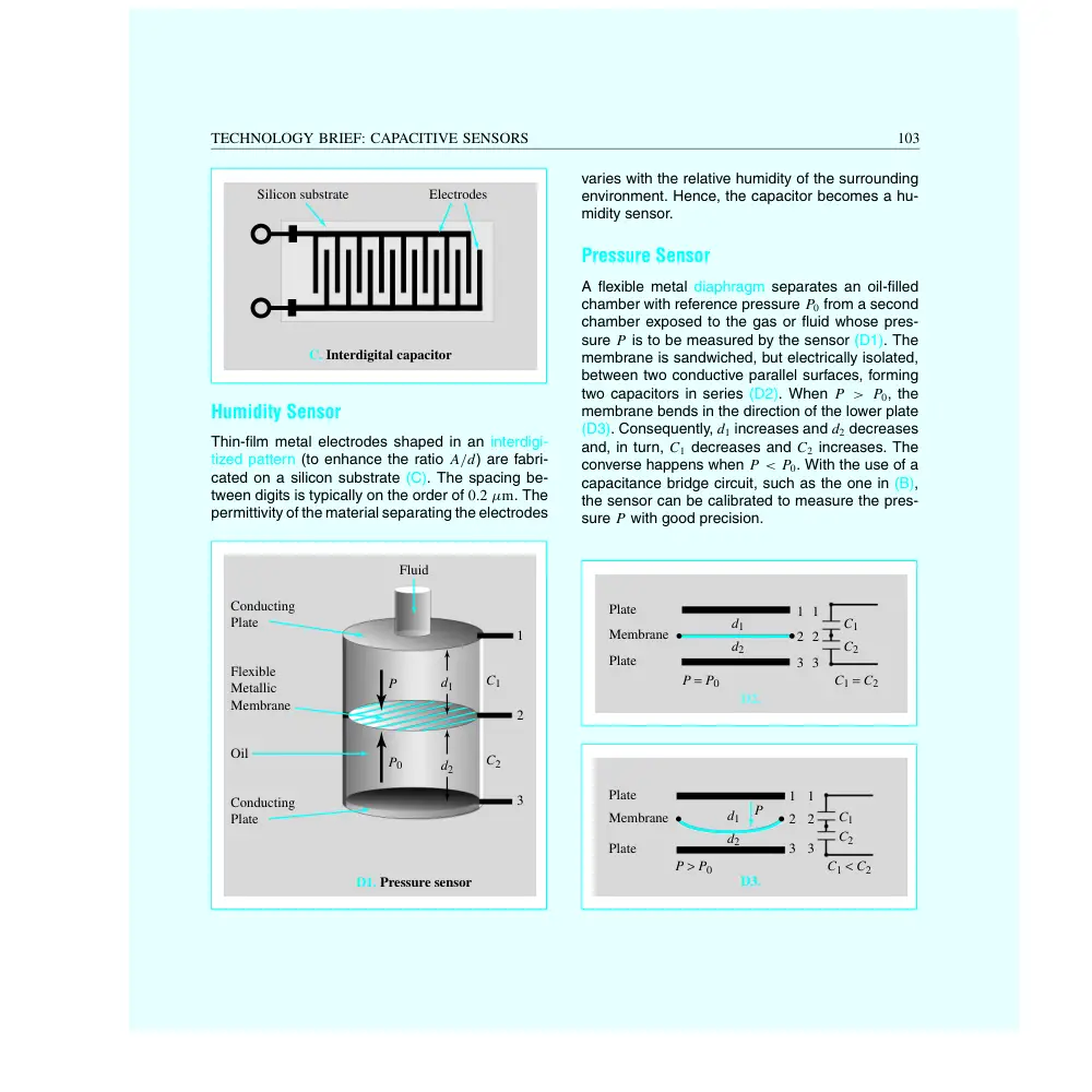
Thin-film metal electrodes shaped in an interdigi-
tized pattern (to enhance the ratio A/d) are fabri-
cated on a silicon substrate (C). The spacing be-
tween digits is typically on the order of 0.2 µm. The
permittivity of the material separating the electrodes
D1. Pressure sensor
Fluid
Conducting
Plate
Flexible
Metallic
Membrane
Oil
Conducting
Plate
1
2
3
C1
d1
C2
P
P0
d2
varies with the relative humidity of the surrounding
environment. Hence, the capacitor becomes a hu-
midity sensor.
Pressure Sensor
A flexible metal diaphragm separates an oil-filled
chamber with reference pressure P0 from a second
chamber exposed to the gas or fluid whose pres-
sure P is to be measured by the sensor (D1). The
membrane is sandwiched, but electrically isolated,
between two conductive parallel surfaces, forming
two capacitors in series (D2). When P > P0, the
membrane bends in the direction of the lower plate
(D3). Consequently, d1 increases and d2 decreases
and, in turn, C1 decreases and C2 increases. The
converse happens when P < P0. With the use of a
capacitance bridge circuit, such as the one in (B),
the sensor can be calibrated to measure the pres-
sure P with good precision.
D2.
Plate
Membrane
Plate
1
2
C1
C2
d1
d2
3
1
2
3
C1 = C2
P = P0
D3.
Plate
Membrane
Plate
1
2
C1
P
C2
d1
d2
3
1
2
3
C1 < C2
P > P0