
MECH 320 Final, Spring 2014
American University of Beirut · Mechanics of Materials · 5 pages

More MECH 320 files
- Final · Summer 2011Final examView
- Final with Solution · Spring 2010Final exam · with solutionView
- Midterm · Spring 2012ExamView
- Exam 1 Solution · Spring 2011Exam · with solutionView
- Exam 1 · Spring 2011ExamView
- Exam 1 · Summer 2011ExamView
- Questions Ch 4 & 2.1 Hints for Exam · Summer 2011ProblemsView
- Exam 2 · Summer 2011ExamView
Show the text of this final exam
STUDENT NAME:
ID:
Final Exam
May 15, 2013
Spring semester 2012-2013
Instructor: Mutasem Shehadeh, Amer El Souri
Two Hours
1
MECH 320-Mechanics of Materials
AMERICAN UNIVERSITY OF BEIRUT
Problem 1: 15 pts
For each of the plane stress states below, draw a Mohr’s circle diagram properly labeled,
find the
Principal normal stresses, the maximum in-plane shear stress, and the absolute maximum
shear stress
a)
x= 12 MPa,
y= 6 MPa,
xy= 4 MPa cw (clockwise)
b)
x= 6 MPa,
y= -5 MPa,
xy=8 MPa ccw (counter clockwise)
Problem 2: 15 pts
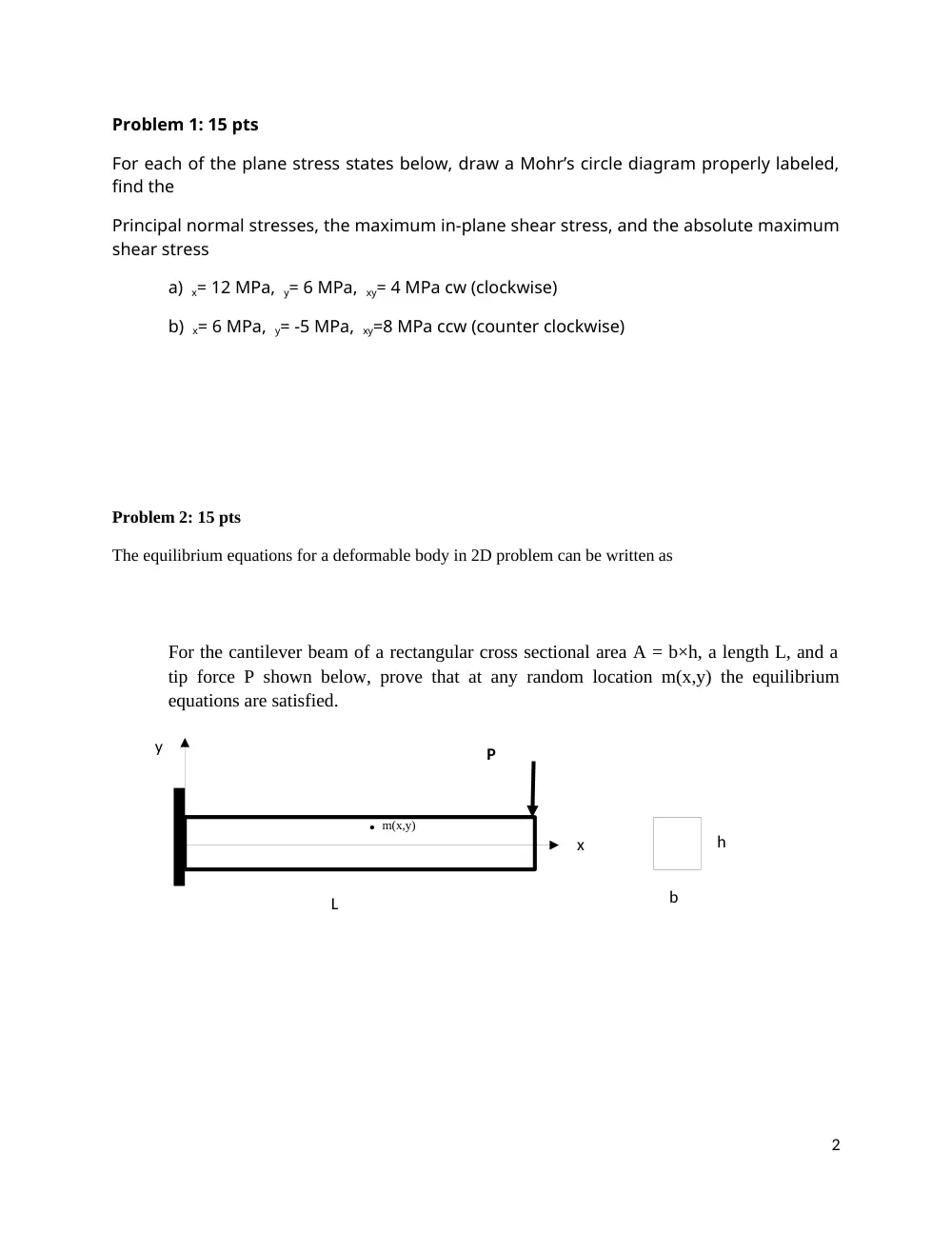
The equilibrium equations for a deformable body in 2D problem can be written as
For the cantilever beam of a rectangular cross sectional area A = b×h, a length L, and a
tip force P shown below, prove that at any random location m(x,y) the equilibrium
equations are satisfied.
2
L
h
. m(x,y)
P
x
y
b
P
T
6m
6m
a
a
Problem 3: 20 pts
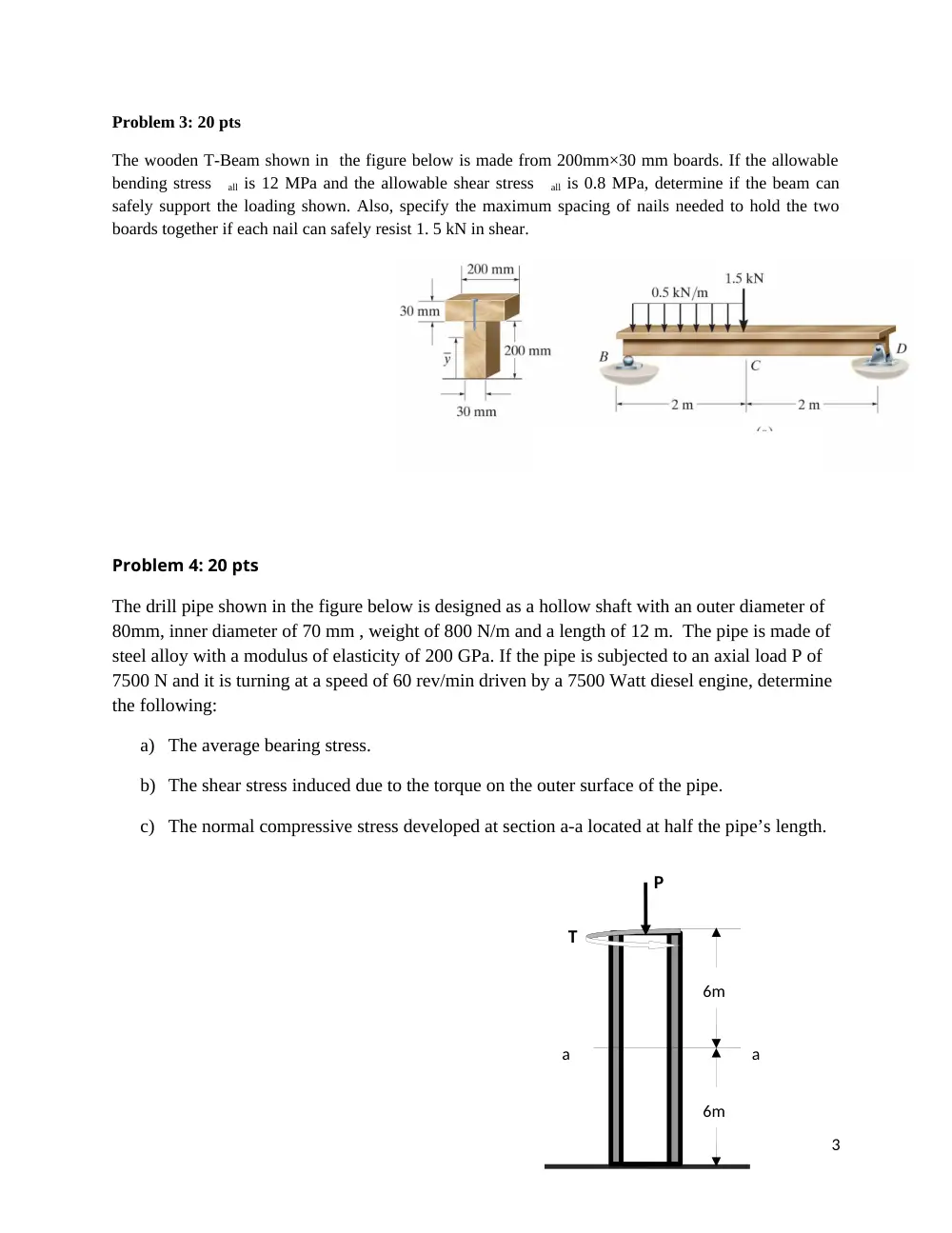
The wooden T-Beam shown in the figure below is made from 200mm×30 mm boards. If the allowable
bending stress all is 12 MPa and the allowable shear stress all is 0.8 MPa, determine if the beam can
safely support the loading shown. Also, specify the maximum spacing of nails needed to hold the two
boards together if each nail can safely resist 1. 5 kN in shear.
Problem 4: 20 pts
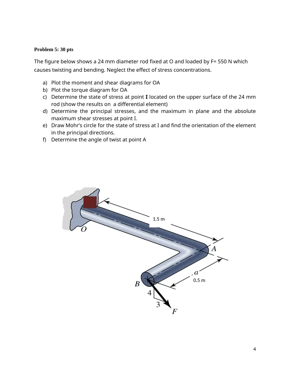
The drill pipe shown in the figure below is designed as a hollow shaft with an outer diameter of
80mm, inner diameter of 70 mm , weight of 800 N/m and a length of 12 m. The pipe is made of
steel alloy with a modulus of elasticity of 200 GPa. If the pipe is subjected to an axial load P of
7500 N and it is turning at a speed of 60 rev/min driven by a 7500 Watt diesel engine, determine
the following:
a) The average bearing stress.
b) The shear stress induced due to the torque on the outer surface of the pipe.
c) The normal compressive stress developed at section a-a located at half the pipe’s length.
3
Problem 5: 30 pts
The figure below shows a 24 mm diameter rod fixed at O and loaded by F= 550 N which
causes twisting and bending. Neglect the effect of stress concentrations.
a) Plot the moment and shear diagrams for OA
b) Plot the torque diagram for OA
c)
Determine the state of stress at point I located on the upper surface of the 24 mm
rod (show the results on a differential element)
d) Determine the principal stresses, and the maximum in plane and the absolute
maximum shear stresses at point I.
e) Draw Mohr’s circle for the state of stress at I and find the orientation of the element
in the principal directions.
f)
Determine the angle of twist at point A
4
I
1.5 m
0.5 m
5