
MECH 320 Final with Solution, Spring 2010
American University of Beirut · Mechanics of Materials · 9 pages · Dr. Mohamad Nassereddine · with solution

More MECH 320 files
- Final · Spring 2014Final examView
- Final · Summer 2011Final examView
- Midterm · Spring 2012ExamView
- Exam 1 Solution · Spring 2011Exam · with solutionView
- Exam 1 · Spring 2011ExamView
- Exam 1 · Summer 2011ExamView
- Questions Ch 4 & 2.1 Hints for Exam · Summer 2011ProblemsView
- Exam 2 · Summer 2011ExamView
Show the text of this final exam
MECH 320-Mechanics of Materials
AMERICAN UNIVERSITY OF BEIRUT
STUDENT NAME:
ID:
Spring semester 2009-2010
Instructors: Shehadeh M., and Nasser-Eddin M.
TIME ALLOWED: 2H
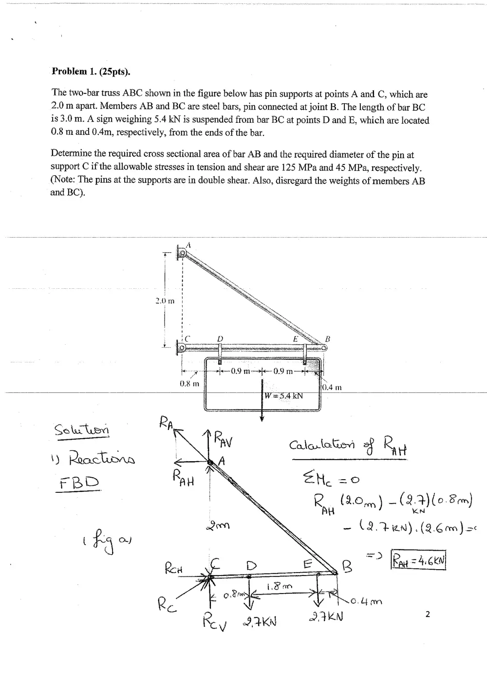
Problem 1. (25pts).
The two-bar truss ABC shown in the figure below has pin supports at points A and C, which are
2.0 m apart. Members AB and BC are steel bars, pin connected at joint B. The length of bar BC
is 3.0 m. A sign weighing 5.4 KN is suspended from bar BC at points D and E, which are located
0.8 m and 0.4m, respectively, from the ends of the bar.
Determine the required cross sectional area of bar AB and the required diameter of the pin at
support C if the allowable stresses in tension and shear are 125 MPa and 45 MPa, respectively.
(Note: The pins at the supports are in double shear. Also, disregard the weights of members AB
and BC).
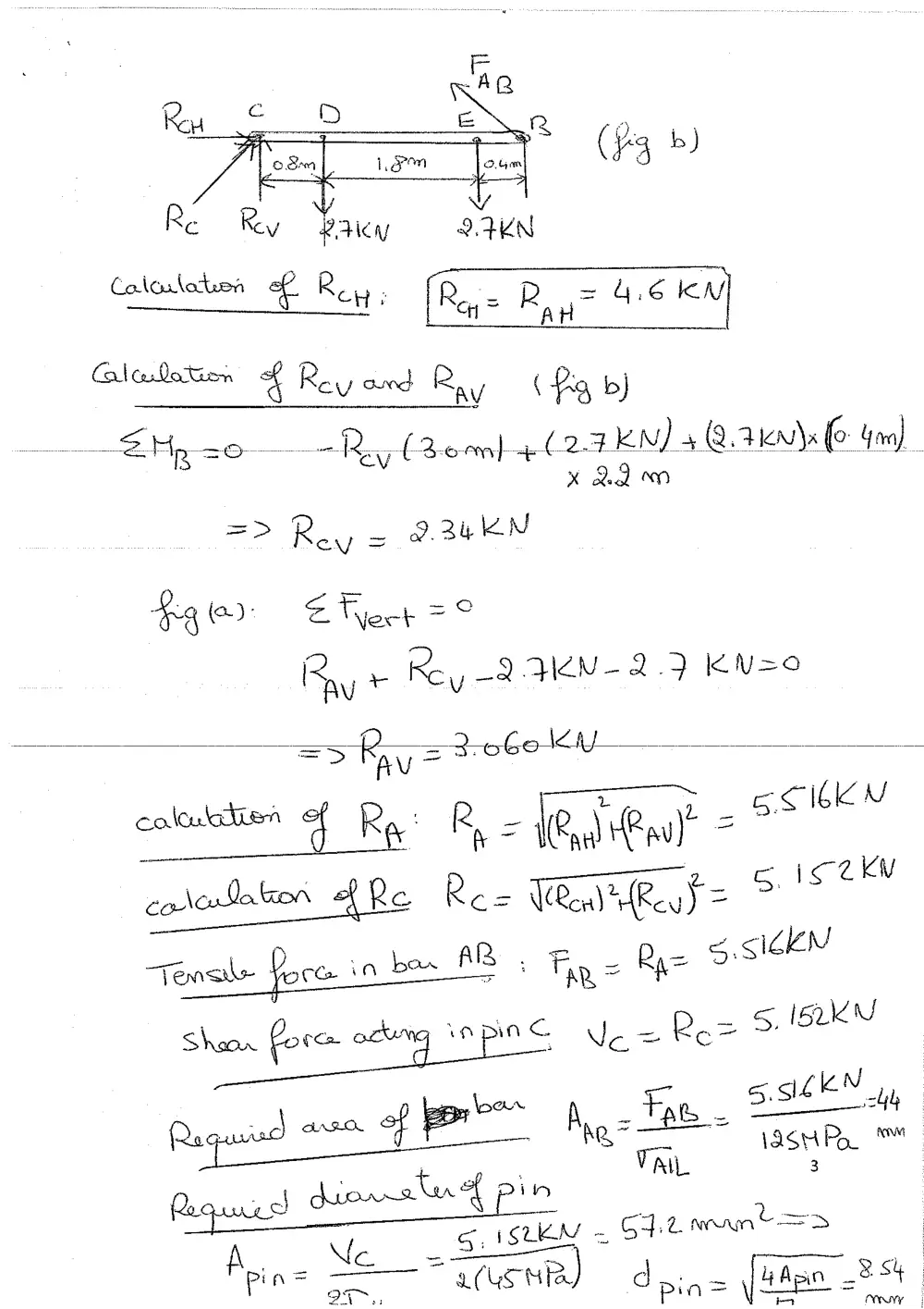
Caladation 4 Rey cued Ray (Pg b)
SE Hp co Ry, (Remmmh 4 (24 EN) 4 QAM br
x 2Qom
; _ reas
coloration fe Re= TR iReuS= >
| = _ 2 siZeN
“Tense feces in ben PDs Thy = Bee °
| _ 5, ISkKN
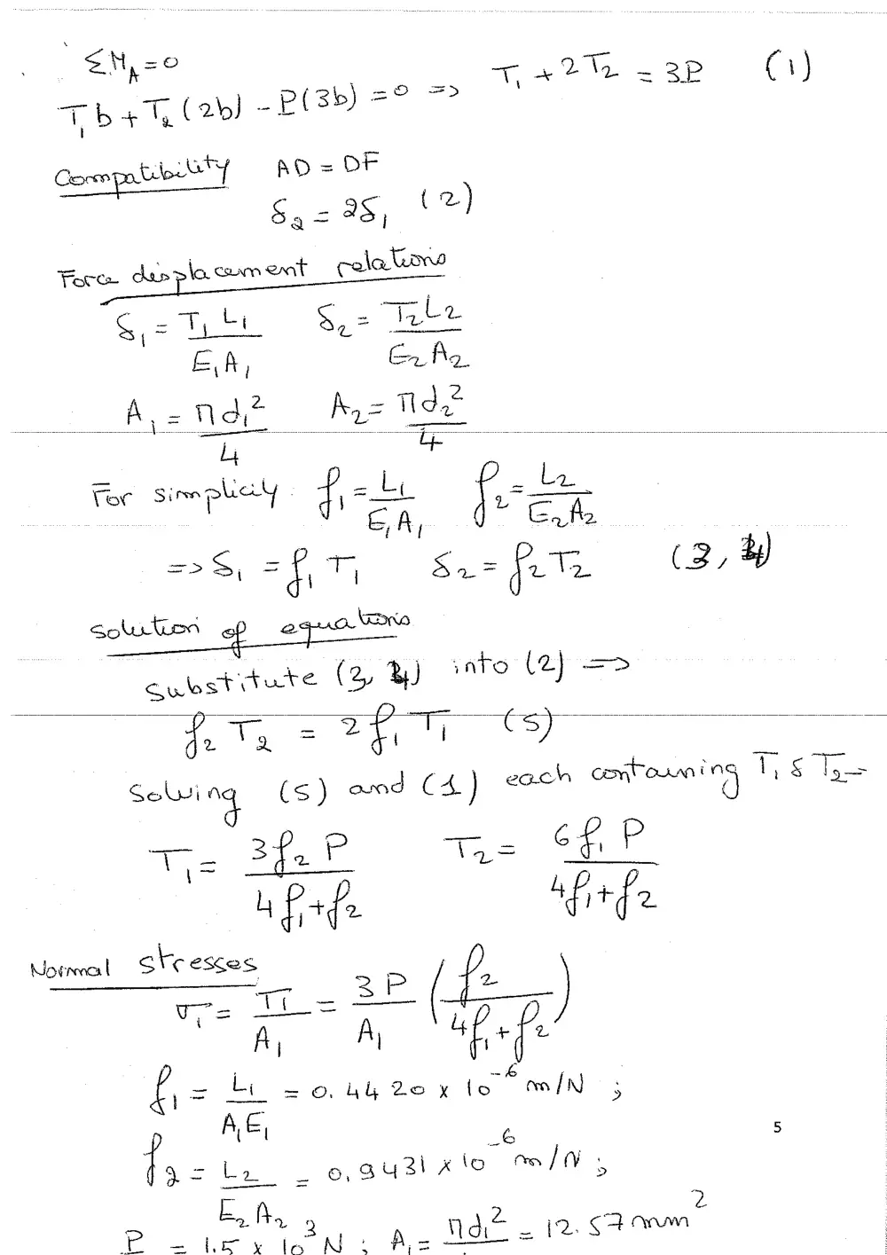
- Problem 2.(25 pts)
A horizontal rigid bar AB is pinned at end A and supported by two wires CD and EF at points D
and F as shown in the figure below. A vertical load P=1.5 KN acts at end B of the bar. The bar
has a length =3b. The wires CD and EF have length L,=0.40m and L.=0.30 m. Also the wires
CD and EF have diameters of 4 mm and 3mm respectively. The wire CD is made of aluminum
with E4i=72 GPa while the wire EF is made of Magnesium with Eye=45 GPa knowing that the
allowable stresses in the Aluminum and Magnesium wires are 200 MPa and 175 MPa
respectively
a-Calculate the normal stresses in bars EF and CD.
adequate.
—b-By-reference-to-the-values-found-in-part-a; determine if the materials used-itt “the design are
. ~&
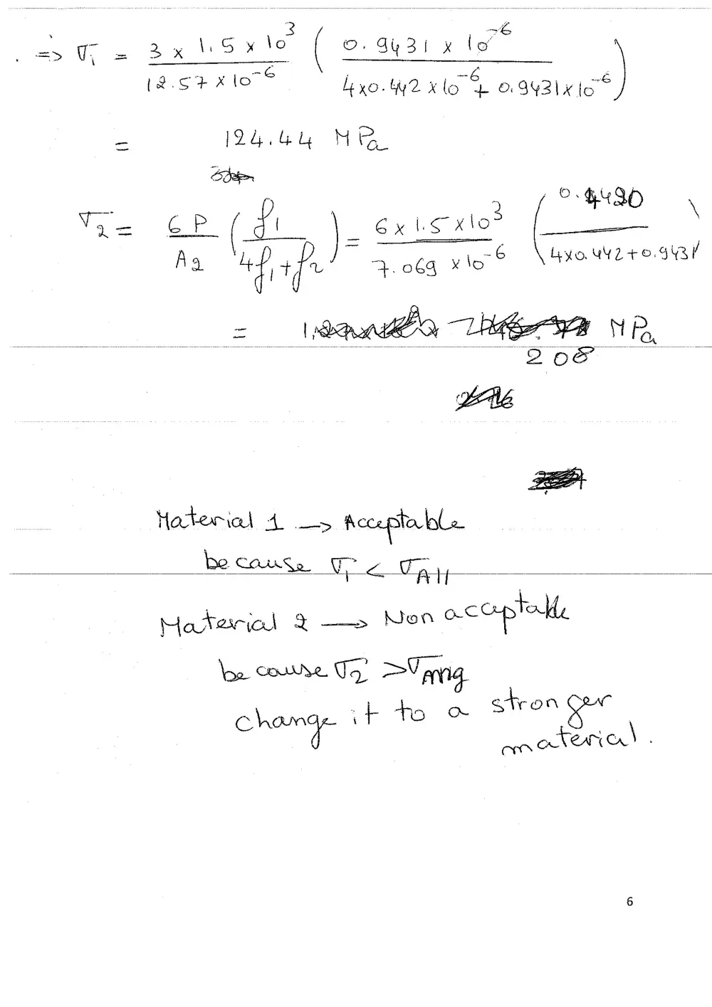
= = Bx lsxte ( ©. 4431 x lo
a ee:
lexo. 42 x lo pase’)
[24.4 Mi
. p 2 OHIO \
Vo= > Je. Gx io xlo (—
lor corre Tq’ >Varnig
; 7 As foe oty On
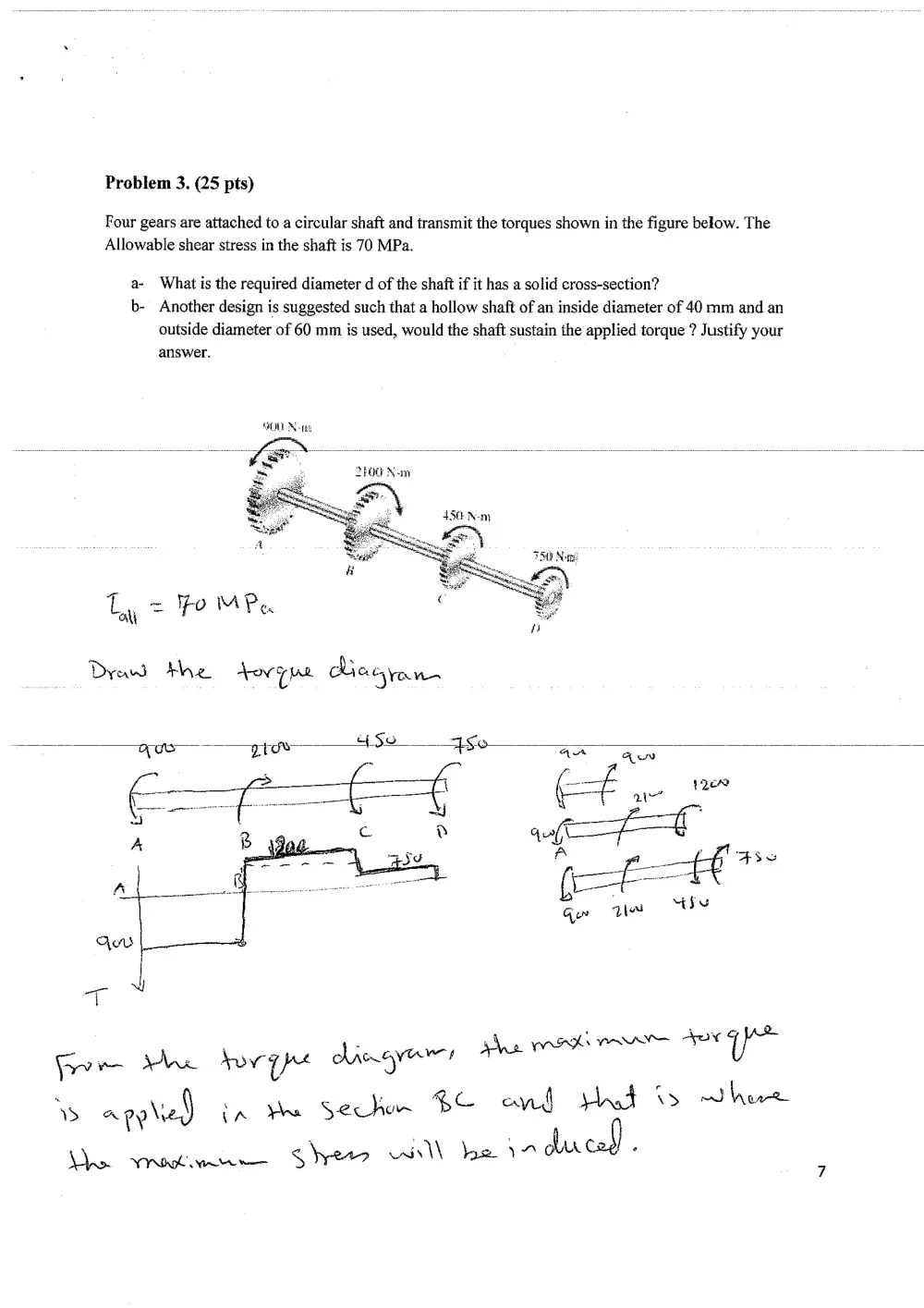
Problem 3. (25 pts)
Four gears are attached to a circular shaft and transmit the torques shown in the figure below. The
Allowable shear stress in the shaft is 70 MPa.
a- What is the required diameter d of the shaft if it has a solid cross-section?
b- Another design is suggested such that a hollow shaft of an inside diameter of 40 mm and an
outside diameter of 60 mm is used, would the shaft sustain the applied torque ? Justify your
answer.
t
aly
= Yom Pa
Draw dhe joven Ces hone
aw SZ
. .
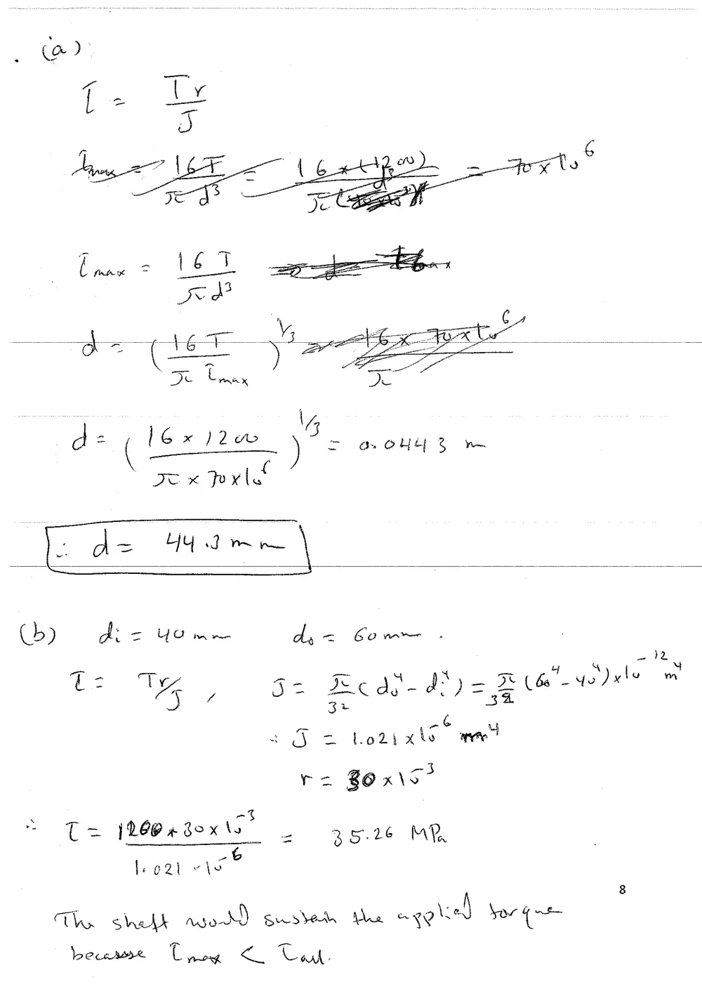
TI: Ty ee Ke Qh. My = Rw ve) xle om
u A y Jt Ec del FS) = at
U6
Sz tots xhs mee
ra BO x\S°
_ =F
C= 126@sbex's 2 35.26 MR
x
le e2t ie
&
The shel asorX) susteth We aid sor Qe
pece C poe < ere
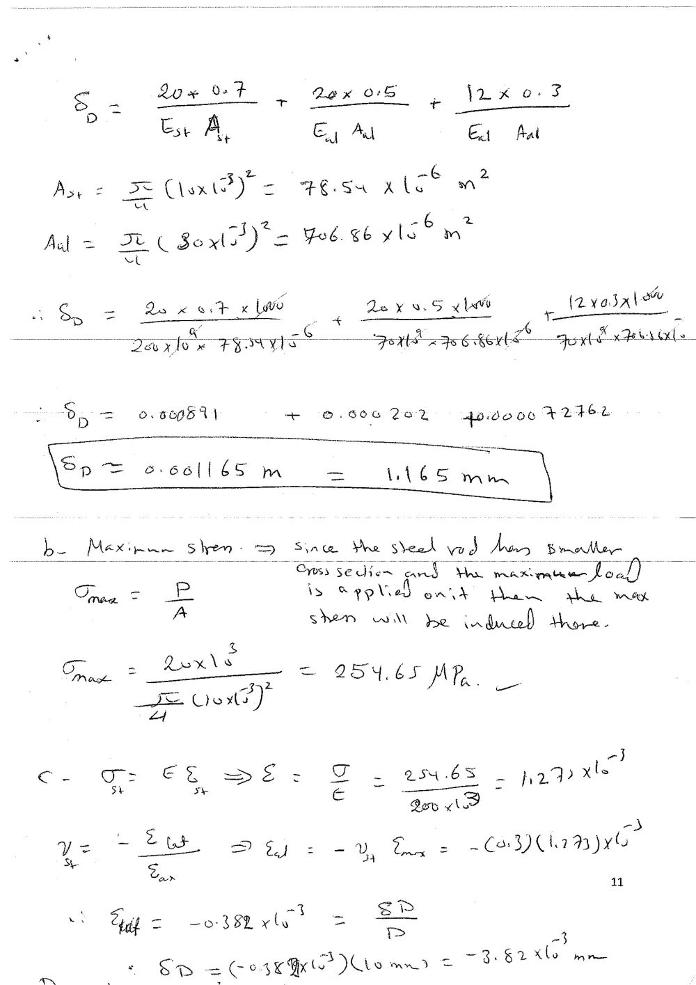
D> ¢ (2% OP
Est A, Gy Au Ext fat
3 -~& 2
As = Se Cloxt®) = FES XLET
oe
5 mm
Aal = C 3 i ee = Yos. 6 vlc
7
So = 2xet «we Lexy 9.5 yl izvasalow
° : G ‘ . A r “
28 x, Te oe EPI —" Fett Fs 6h Fort Rama - ac Los 2
oe => oO. b66f574 + ©.606 2e2 4o.dooe F24EL
be Mex: Toca Shen: 2D See re sveok wa Aes Bethe
~ Oyys5 se ew cand Sas many mw foal)
Orne — PP is seo ef on > ina Paar Wek
ps SHED wt be induced) Move -
&
- al .
Troe = AES = 954.65 MP
_ -3 2 a. VW"
SE Vent?)
Ld
- ‘> <3
c- GO EG >aeE- F = 2H 6S. hey xls
5h sy ‘oom ne) -
Qos ve
ye 2 Sey su, Ey -CoCrayye
. San
11
; - Zp
‘ ep = 0 382 xle = = 3
_ ~3.§2 xo mre
sD = C 6 4X Gx Ue a