
PHY 201 Lecture Chapter 5, Fall 2015
Lebanese American University · Electricit and Magnetism · 32 pages · Dr. Jimmy Romanos



Showing the first 10 of 32 pages. Download the PDF to see all of it.
More PHY 201 files
Show the text of this lab
1115
Chapter 25
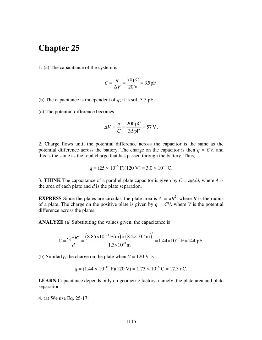
1. (a) The capacitance of the system is
C
q
V
70
20
35
pC
V
. pF.
(b) The capacitance is independent of q; it is still 3.5 pF.
(c) The potential difference becomes
V
q
C
200
35
57
pC
pF
V.
.
2. Charge flows until the potential difference across the capacitor is the same as the
potential difference across the battery. The charge on the capacitor is then q = CV, and
this is the same as the total charge that has passed through the battery. Thus,
q = (25 10–6 F)(120 V) = 3.0 10–3 C.
3. THINK The capacitance of a parallel-plate capacitor is given by C = 0A/d, where A is
the area of each plate and d is the plate separation.
EXPRESS Since the plates are circular, the plate area is A = R2, where R is the radius
of a plate. The charge on the positive plate is given by q = CV, where V is the potential
difference across the plates.
ANALYZE (a) Substituting the values given, the capacitance is
2
12
2
2
10
0
3
8.85 10
F m
8.2 10 m
1.44 10
F 144 pF.
1.3 10 m
R
C
d
(b) Similarly, the charge on the plate when V = 120 V is
q = (1.44 10–10 F)(120 V) = 1.73 10–8 C = 17.3 nC.
LEARN Capacitance depends only on geometric factors, namely, the plate area and plate
separation.
4. (a) We use Eq. 25-17:
CHAPTER 25
1116
2
2
0
9 N m
C
40.0mm
38.0mm
4
84.5 pF.
8.99 10
40.0mm 38.0mm
ab
C
b
a
(b) Let the area required be A. Then C = 0A/(b – a), or
2
12
2
2
0
84.5pF
40.0mm
38.0mm
191cm .
8.85 10
C /N m
C b
a
A
5. Assuming conservation of volume, we find the radius of the combined spheres, then
use C = 40R to find the capacitance. When the drops combine, the volume is doubled. It
is then V = 2(4/3)R3. The new radius R' is given by
3
3
4
2 4
3
3
R
R
p
p
R
21 3 R
.
The new capacitance is
1 3
0
0
0
4
4
2
5.04
.
C
R
R
R
p
p
p
With R = 2.00 mm, we obtain
12
3
13
5.04
8.85 10
F m
2.00 10 m
2.80 10
F
C
.
6. (a) We use C = A0/d. The distance between the plates is
2
12
2
2
12
0
1.00m
8.85 10
C /N m
8.85 10
m.
1.00F
A
d
C
(b) Since d is much less than the size of an atom ( 10–10 m), this capacitor cannot be
constructed.
7. For a given potential difference V, the charge on the surface of the plate is
(
)
q
Ne
nAd e
where d is the depth from which the electrons come in the plate, and n is the density of
conduction electrons. The charge collected on the plate is related to the capacitance and
the potential difference by q
CV
(Eq. 25-1). Combining the two expressions leads to
C
ne d
A
V
.
With
14
/
/
5.0 10
m/V
s
s
d V
d
V
and
28
n 8.49 10 / m3
(see, for example, Sample
Problem 25.01 — “Charging the plates in a parallel-plate capacitor”), we obtain
1117
28
3
19
4
2
(8.49 10
/ m )(1.6 10
C)(5.0 10 14 m/V)
6.79 10 F/m
C
A
.
8. The equivalent capacitance is given by Ceq = q/V, where q is the total charge on all the
capacitors and V is the potential difference across any one of them. For N identical
capacitors in parallel, Ceq = NC, where C is the capacitance of one of them. Thus,
/
NC
q V
and
3
6
1 00C
9 09 10
110V
1 00 10 F
q
.
N
.
.
VC
.
9. The charge that passes through meter A is
q
C V
CV
eq
F
V
C.
3
3 250
4200
0315
.
.
b
gb
g
10. The equivalent capacitance is
C
C
C C
C
C
eq
F
F
F
F
F
F.
3
1
2
1
2
4 00
100
500
100
500
7 33
.
.
.
.
.
.
b
gb
g
11. The equivalent capacitance is
1
2
3
eq
1
2
3
10.0 F
5.00 F
4.00 F
3.16 F.
10.0 F
5.00 F
4.00 F
C
C
C
C
C
C
C
12. The two 6.0 F capacitors are in parallel and are consequently equivalent to
eq
12 F
C
. Thus, the total charge stored (before the squeezing) is
total
eq
12 F (10 0V) 120 C.
q
C V
.
(a) and (b) As a result of the squeezing, one of the capacitors is now 12 F (due to the
inverse proportionality between C and d in Eq. 25-9), which represents an increase of
6.0 F
and thus a charge increase of
total
eq
6 0 F (10 0V)
60 C .
q
C V
.
.
13. THINK Charge remains conserved when a fully charged capacitor is connected to an
uncharged capacitor.
EXPRESS The charge initially on the charged capacitor is given by q = C1V0, where C1
= 100 pF is the capacitance and V0 = 50 V is the initial potential difference. After the
battery is disconnected and the second capacitor wired in parallel to the first, the charge
CHAPTER 25
1118
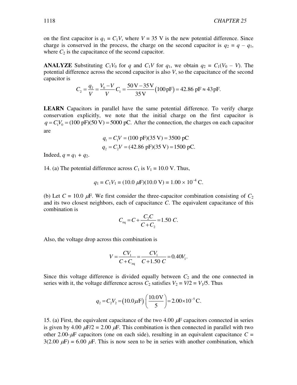
on the first capacitor is q1 = C1V, where V = 35 V is the new potential difference. Since
charge is conserved in the process, the charge on the second capacitor is q2 = q – q1,
where C2 is the capacitance of the second capacitor.
ANALYZE Substituting C1V0 for q and C1V for q1, we obtain q2 = C1(V0 – V). The
potential difference across the second capacitor is also V, so the capacitance of the second
capacitor is
0
2
2
1
50V
35V 100pF
42.86 pF
43pF.
35V
V
V
q
C
C
V
V
LEARN Capacitors in parallel have the same potential difference. To verify charge
conservation explicitly, we note that the initial charge on the first capacitor is
1 0
(100 pF)(50 V)
5000 pC.
q
CV
After the connection, the charges on each capacitor
are
1
1
2
2
(100 pF)(35 V)
3500 pC
(42.86 pF)(35 V)
1500 pC.
q
CV
q
C V
Indeed, q = q1 + q2.
14. (a) The potential difference across C1 is V1 = 10.0 V. Thus,
q1 = C1V1 = (10.0 F)(10.0 V) = 1.00 10–4 C.
(b) Let C = 10.0 F. We first consider the three-capacitor combination consisting of C2
and its two closest neighbors, each of capacitance C. The equivalent capacitance of this
combination is
2
eq
2
1 50
C C
C
C
.
C.
C
C
Also, the voltage drop across this combination is
1
1
1
eq
0 40
1 50
CV
CV
V
.
V .
C
C
C
.
C
Since this voltage difference is divided equally between C2 and the one connected in
series with it, the voltage difference across C2 satisfies V2 = V/2 = V1/5. Thus
5
2
2
2
10 0V
10 0 F
2 00 10 C.
5
.
q
C V
.
.
15. (a) First, the equivalent capacitance of the two 4.00 F capacitors connected in series
is given by 4.00 F/2 = 2.00 F. This combination is then connected in parallel with two
other 2.00-F capacitors (one on each side), resulting in an equivalent capacitance C =
3(2.00 F) = 6.00 F. This is now seen to be in series with another combination, which
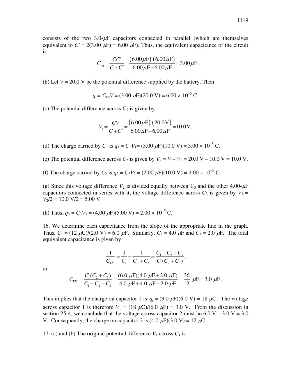
1119
consists of the two 3.0-F capacitors connected in parallel (which are themselves
equivalent to C' = 2(3.00 F) = 6.00 F). Thus, the equivalent capacitance of the circuit
is
eq
6 00 F
6 00 F
3 00 F.
6 00 F 6 00 F
.
.
CC
C
.
C
C
.
.
(b) Let V = 20.0 V be the potential difference supplied by the battery. Then
q = CeqV = (3.00 F)(20.0 V) = 6.00 10–5 C.
(c) The potential difference across C1 is given by
1
6 00 F
20 0V
10 0V
6 00 F 6 00 F
.
.
CV
V
.
.
C
C
.
.
(d) The charge carried by C1 is q1 = C1V1= (3.00 F)(10.0 V) = 3.00 10–5 C.
(e) The potential difference across C2 is given by V2 = V – V1 = 20.0 V – 10.0 V = 10.0 V.
(f) The charge carried by C2 is q2 = C2V2 = (2.00 F)(10.0 V) = 2.00 10–5 C.
(g) Since this voltage difference V2 is divided equally between C3 and the other 4.00-F
capacitors connected in series with it, the voltage difference across C3 is given by V3 =
V2/2 = 10.0 V/2 = 5.00 V.
(h) Thus, q3 = C3V3 = (4.00 F)(5.00 V) = 2.00 10–5 C.
16. We determine each capacitance from the slope of the appropriate line in the graph.
Thus, C1 = (12 C)/(2.0 V) = 6.0 F. Similarly, C2 = 4.0 F and C3 = 2.0 F. The total
equivalent capacitance is given by
1
2
3
123
1
2
3
1
2
3
1
1
1
(
)
C
C
C
C
C
C
C
C C
C
,
or
1
2
3
123
1
2
3
(
)
(6.0 F)(4.0 F
2.0 F)
36 F
3.0 F
6.0 F
4.0 F
2.0 F
12
C C
C
C
C
C
C
.
This implies that the charge on capacitor 1 is
1q (3.0 F)(6.0 V) = 18 C. The voltage
across capacitor 1 is therefore V1 = (18 C)/(6.0 F) = 3.0 V. From the discussion in
section 25-4, we conclude that the voltage across capacitor 2 must be 6.0 V – 3.0 V = 3.0
V. Consequently, the charge on capacitor 2 is (4.0 F)(3.0 V) = 12 C.
17. (a) and (b) The original potential difference V1 across C1 is
CHAPTER 25
1120
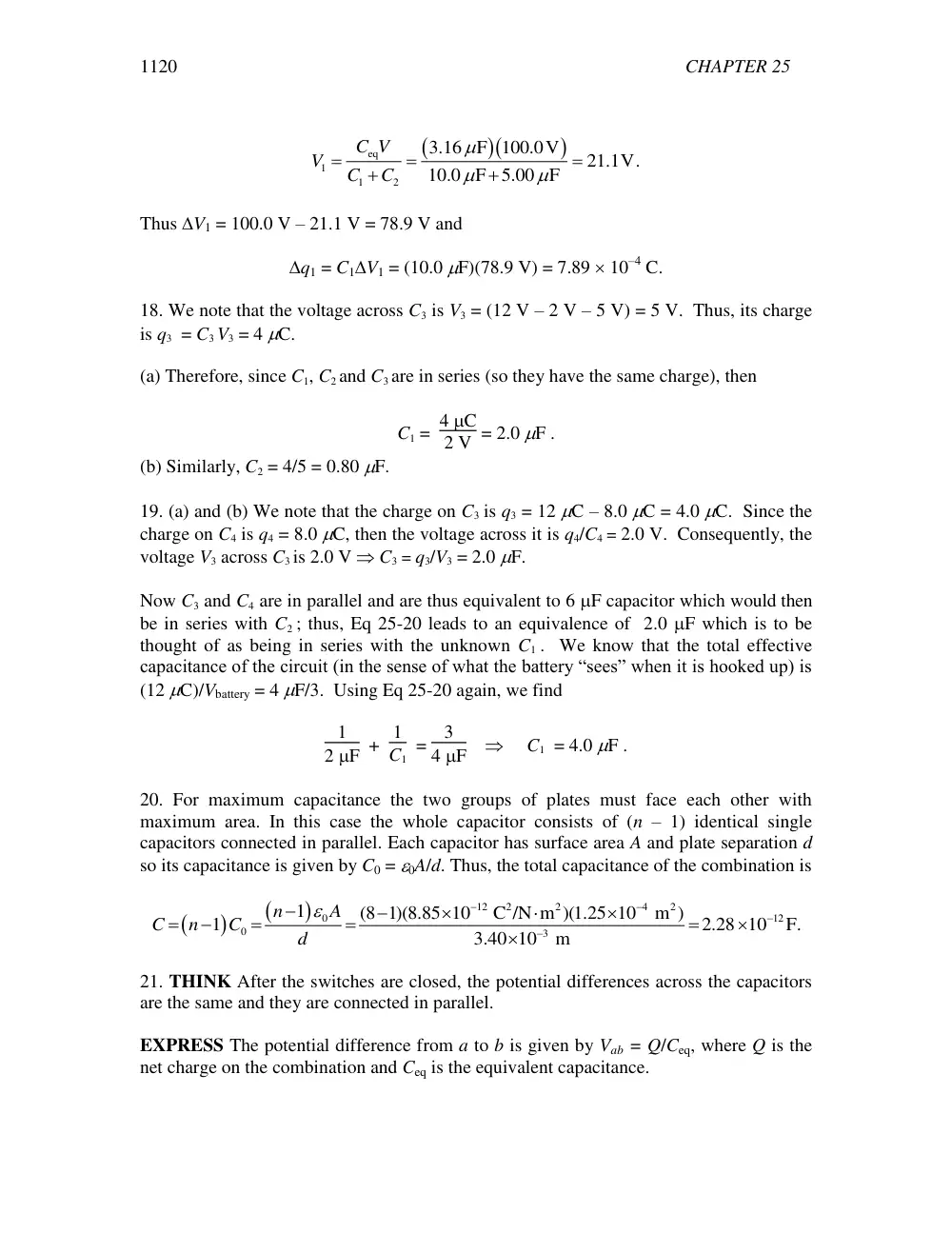
eq
1
1
2
3.16 F 100.0V
21.1V.
10.0 F
5.00 F
C V
V
C
C
Thus V1 = 100.0 V – 21.1 V = 78.9 V and
q1 = C1V1 = (10.0 F)(78.9 V) = 7.89 10–4 C.
18. We note that the voltage across C3 is V3 = (12 V – 2 V – 5 V) = 5 V. Thus, its charge
is q3 = C3 V3 = 4 C.
(a) Therefore, since C1, C2 and C3 are in series (so they have the same charge), then
C1 = 4 C
2 V = 2.0 F .
(b) Similarly, C2 = 4/5 = 0.80 F.
19. (a) and (b) We note that the charge on C3 is q3 = 12 C – 8.0 C = 4.0 C. Since the
charge on C4 is q4 = 8.0 C, then the voltage across it is q4/C4 = 2.0 V. Consequently, the
voltage V3 across C3 is 2.0 V C3 = q3/V3 = 2.0 F.
Now C3 and C4 are in parallel and are thus equivalent to 6 F capacitor which would then
be in series with C2 ; thus, Eq 25-20 leads to an equivalence of 2.0 F which is to be
thought of as being in series with the unknown C1 . We know that the total effective
capacitance of the circuit (in the sense of what the battery “sees” when it is hooked up) is
(12 C)/Vbattery = 4 F/3. Using Eq 25-20 again, we find
1
2F + 1
C1 = 3
4F C1 = 4.0 F .
20. For maximum capacitance the two groups of plates must face each other with
maximum area. In this case the whole capacitor consists of (n – 1) identical single
capacitors connected in parallel. Each capacitor has surface area A and plate separation d
so its capacitance is given by C0 = 0A/d. Thus, the total capacitance of the combination is
12
2
2
4
2
0
12
0
3
1
(8 1)(8.85 10
C /N m )(1.25 10 m )
1
2.28 10
F.
3.40 10 m
n
A
C
n
C
d
21. THINK After the switches are closed, the potential differences across the capacitors
are the same and they are connected in parallel.
EXPRESS The potential difference from a to b is given by Vab = Q/Ceq, where Q is the
net charge on the combination and Ceq is the equivalent capacitance.
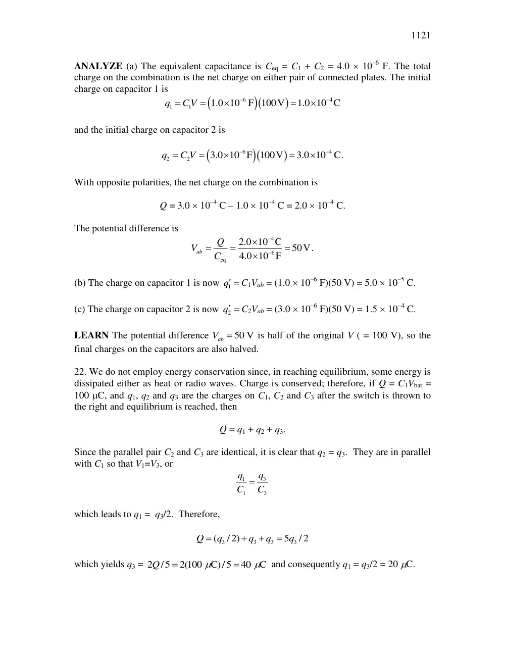
1121
ANALYZE (a) The equivalent capacitance is Ceq = C1 + C2 = 4.0 10–6 F. The total
charge on the combination is the net charge on either pair of connected plates. The initial
charge on capacitor 1 is
6
4
1
1
1.0 10
F 100V
1.0 10 C
q
CV
and the initial charge on capacitor 2 is
6
4
2
2
3.0 10 F 100V
3.0 10
C.
q
C V
With opposite polarities, the net charge on the combination is
Q = 3.0 10–4 C – 1.0 10–4 C = 2.0 10–4 C.
The potential difference is
4
6
eq
2.0 10 C
50V.
4.0 10 F
ab
Q
V
C
(b) The charge on capacitor 1 is now
1q C1Vab = (1.0 10–6 F)(50 V) = 5.0 10–5 C.
(c) The charge on capacitor 2 is now
2q C2Vab = (3.0 10–6 F)(50 V) = 1.5 10–4 C.
LEARN The potential difference
50 V
Vab
is half of the original V ( = 100 V), so the
final charges on the capacitors are also halved.
22. We do not employ energy conservation since, in reaching equilibrium, some energy is
dissipated either as heat or radio waves. Charge is conserved; therefore, if Q = C1Vbat =
100 C, and q1, q2 and q3 are the charges on C1, C2 and C3 after the switch is thrown to
the right and equilibrium is reached, then
Q = q1 + q2 + q3.
Since the parallel pair C2 and C3 are identical, it is clear that q2 = q3. They are in parallel
with C1 so that V1=V3, or
3
1
1
3
q
q
C
C
which leads to q1 = q3/2. Therefore,
3
3
3
3
(
/ 2)
5
/ 2
Q
q
q
q
q
which yields q3 = 2
/5
2(100 C)/5
40 C
Q
and consequently q1 = q3/2 = 20 C.
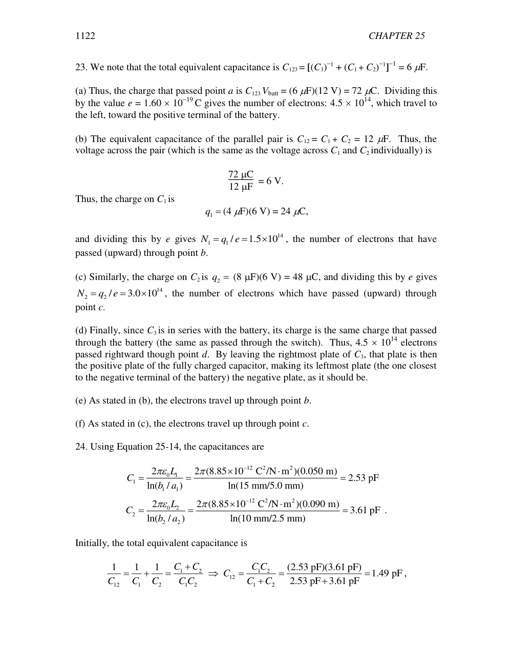
CHAPTER 25
1122
23. We note that the total equivalent capacitance is C123 = [(C3)1 + (C1 + C2)1]1 = 6 F.
(a) Thus, the charge that passed point a is C123 Vbatt = (6 F)(12 V) = 72 C. Dividing this
by the value e = 1.60 1019 C gives the number of electrons: 4.5 1014, which travel to
the left, toward the positive terminal of the battery.
(b) The equivalent capacitance of the parallel pair is C12 = C1 + C2 = 12 F. Thus, the
voltage across the pair (which is the same as the voltage across C1 and C2 individually) is
72 C
12 F = 6 V.
Thus, the charge on C1 is
1q (4 F)(6 V) = 24 C,
and dividing this by e gives
14
1
1 /
1.5 10
N
q
e
, the number of electrons that have
passed (upward) through point b.
(c) Similarly, the charge on C2 is
2q (8 F)(6 V) = 48 C, and dividing this by e gives
14
2
2 /
3.0 10
N
q
e
, the number of electrons which have passed (upward) through
point c.
(d) Finally, since C3 is in series with the battery, its charge is the same charge that passed
through the battery (the same as passed through the switch). Thus, 4.5 1014 electrons
passed rightward though point d. By leaving the rightmost plate of C3, that plate is then
the positive plate of the fully charged capacitor, making its leftmost plate (the one closest
to the negative terminal of the battery) the negative plate, as it should be.
(e) As stated in (b), the electrons travel up through point b.
(f) As stated in (c), the electrons travel up through point c.
24. Using Equation 25-14, the capacitances are
12
2
2
0
1
1
1
1
12
2
2
0
2
2
2
2
2
2 (8.85 10
C /N m )(0.050 m)
2.53 pF
ln(
/
)
ln(15 mm/5.0 mm)
2
2 (8.85 10
C /N m )(0.090 m)
3.61 pF .
ln(
/
)
ln(10 mm/2.5 mm)
L
C
b
a
L
C
b
a
Initially, the total equivalent capacitance is
1
2
1
2
12
12
1
2
1
2
1
2
1
1
1
(2.53 pF)(3.61 pF)
1.49 pF
2.53 pF
3.61 pF
C
C
C C
C
C
C
C
C C
C
C
,
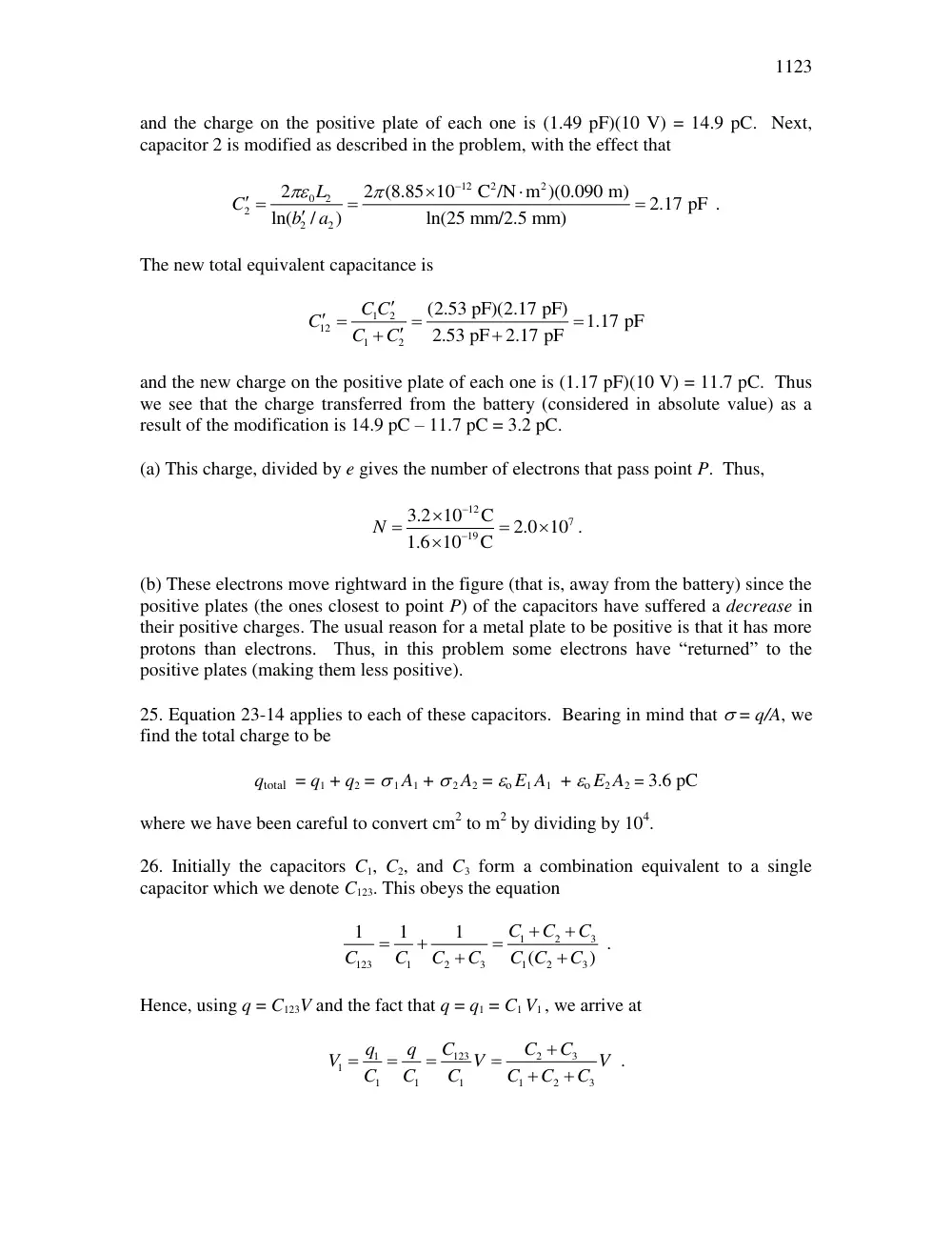
1123
and the charge on the positive plate of each one is (1.49 pF)(10 V) = 14.9 pC. Next,
capacitor 2 is modified as described in the problem, with the effect that
12
2
2
0
2
2
2
2
2
2 (8.85 10
C /N m )(0.090 m)
2.17 pF .
ln(
/
)
ln(25 mm/2.5 mm)
L
C
b
a
The new total equivalent capacitance is
1
2
12
1
2
(2.53 pF)(2.17 pF)
1.17 pF
2.53 pF
2.17 pF
C C
C
C
C
and the new charge on the positive plate of each one is (1.17 pF)(10 V) = 11.7 pC. Thus
we see that the charge transferred from the battery (considered in absolute value) as a
result of the modification is 14.9 pC – 11.7 pC = 3.2 pC.
(a) This charge, divided by e gives the number of electrons that pass point P. Thus,
12
7
19
3.2 10
C
2.0 10
1.6 10
C
N
.
(b) These electrons move rightward in the figure (that is, away from the battery) since the
positive plates (the ones closest to point P) of the capacitors have suffered a decrease in
their positive charges. The usual reason for a metal plate to be positive is that it has more
protons than electrons. Thus, in this problem some electrons have “returned” to the
positive plates (making them less positive).
25. Equation 23-14 applies to each of these capacitors. Bearing in mind that = q/A, we
find the total charge to be
qtotal = q1 + q2 = 1 A1 + 2 A2 = o E1 A1 + o E2 A2 = 3.6 pC
where we have been careful to convert cm2 to m2 by dividing by 104.
26. Initially the capacitors C1, C2, and C3 form a combination equivalent to a single
capacitor which we denote C123. This obeys the equation
1
2
3
123
1
2
3
1
2
3
1
1
1
(
)
C
C
C
C
C
C
C
C C
C
.
Hence, using q = C123V and the fact that q = q1 = C1 V1 , we arrive at
123
2
3
1
1
1
1
1
1
2
3
C
C
C
q
q
V
V
V
C
C
C
C
C
C
.
CHAPTER 25
1124
(a) As C3 this expression becomes V1 = V. Since the problem states that V1
approaches 10 volts in this limit, so we conclude V = 10 V.
(b) and (c) At C3 = 0, the graph indicates V1 = 2.0 V. The above expression consequently
implies C1 = 4C2. Next we note that the graph shows that, at C3 = 6.0 F, the voltage
across C1 is exactly half of the battery voltage. Thus,
1
2 =
C2 + 6.0 F
C1 + C2 + 6.0 F =
C2 + 6.0 F
4C2 + C2 + 6.0 F
which leads to C2 = 2.0 F. We conclude, too, that C1 = 8.0 F.
27. (a) In this situation, capacitors 1 and 3 are in series, which means their charges are
necessarily the same:
1
3
1
3
1
3
1.00 F
3.00 F
12.0V
9.00 C.
1.00 F+3.00 F
C C V
q
q
C
C
(b) Capacitors 2 and 4 are also in series:
2
4
2
4
2
4
2.00 F
4.00 F
12.0V
16.0 C.
2.00 F 4.00 F
C C V
q
q
C
C
(c)
3
1
9.00 C.
q
q
(d)
4
2
16.0 C.
q
q
(e) With switch 2 also closed, the potential difference V1 across C1 must equal the
potential difference across C2 and is
3
4
1
1
2
3
4
3.00 F 4.00 F 12.0V
8.40 V.
1.00 F 2.00 F 3.00 F 4.00 F
C
C
V
V
C
C
C
C
Thus, q1 = C1V1 = (1.00 F)(8.40 V) = 8.40 C.
(f) Similarly, q2 = C2V1 = (2.00 F)(8.40 V) = 16.8 C.
(g) q3 = C3(V – V1) = (3.00 F)(12.0 V – 8.40 V) = 10.8 C.
(h) q4 = C4(V – V1) = (4.00 F)(12.0 V – 8.40 V) = 14.4 C.
28. The charges on capacitors 2 and 3 are the same, so these capacitors may be replaced
by an equivalent capacitance determined from
1125
1
1
1
2
3
2
3
2
3
C
C
C
C
C
C C
eq
.
Thus, Ceq = C2C3/(C2 + C3). The charge on the equivalent capacitor is the same as the
charge on either of the two capacitors in the combination, and the potential difference
across the equivalent capacitor is given by q2/Ceq. The potential difference across
capacitor 1 is q1/C1, where q1 is the charge on this capacitor. The potential difference
across the combination of capacitors 2 and 3 must be the same as the potential difference
across capacitor 1, so q1/C1 = q2/Ceq.
Now, some of the charge originally on capacitor 1 flows to the combination of 2 and 3. If
q0 is the original charge, conservation of charge yields q1 + q2 = q0 = C1 V0, where V0 is
the original potential difference across capacitor 1.
(a) Solving the two equations
1
2
1
eq
1
2
1
0
q
q
C
C
q
q
CV
for q1 and q2, we obtain
2
2
2
1
2
3
0
1
0
1
0
1
2
3
eq
1
1
2
1
3
2
3
1
2
3
.
C
C
C V
C V
C V
q
C C
C
C
C C
C C
C C
C
C
C
With V0 = 12.0 V, C1= 4.00 F, C2= 6.00 F and C3 =3.00 F, we find Ceq = 2.00 F and
q1 = 32.0 C.
(b) The charge on capacitors 2 is
2
1 0
1
(4.00 F)(12.0 V) 32.0
C 16.0
C
q
CV
q
.
(c) The charge on capacitor 3 is the same as that on capacitor 2:
3
1 0
1
(4.00
F)(12.0 V) 32.0
C 16.0
C
q
CV
q
.
29. The energy stored by a capacitor is given by U
CV
1
2
2 , where V is the potential
difference across its plates. We convert the given value of the energy to Joules. Since
1 J
1 W s,
we multiply by (103 W/kW)(3600 s/h) to obtain
7
10 kW h
3.6 10 J
. Thus,
C
U
V
2
2 36 10
1000
72
2
7
2
.
J
V
F.
c
h
b
g
CHAPTER 25
1126
30. Let = 1.00 m3. Using Eq. 25-25, the energy stored is
2
2
2
12
3
8
0
2
1
1
C
8.85 10
150V m
1.00m
9.96 10
J.
2
2
N m
U
u
E
31. THINK The total electrical energy is the sum of the energies stored in the individual
capacitors.
EXPRESS The energy stored in a charged capacitor is
2
2
1
.
2
2
q
U
CV
C
Since we have two capacitors that are connected in parallel, the potential difference V
across the capacitors is the same and the total energy is
2
tot
1
2
1
2
1
.
2
U
U
U
C
C V
ANALYZE Substituting the values given, we have
2
2
6
6
1
2
1
1 2.0 10
F
4.0 10
F
300V
0.27J.
2
2
U
C
C V
LEARN The energy stored in a capacitor is equal to the amount of work required to
charge the capacitor.
32. (a) The capacitance is
12
2
2
4
2
11
0
3
8.85 10
C /N m
40 10
m
3.5 10
F
35pF.
1.0 10 m
A
C
d
(b) q = CV = (35 pF)(600 V) = 2.1 10–8 C = 21 nC.
(c) U
CV
1
2
2
1
2
2
6
35
21
63 10
pF
nC
J = 6.3 J.
b
gb
g
.
(d) E = V/d = 600 V/1.0 10–3 m = 6.0 105 V/m.
(e) The energy density (energy per unit volume) is
1127
6
3
4
2
3
6.3 10 J
1.6 J m .
40 10 m
1.0 10 m
U
u
Ad
33. We use
2
0
/ 4
/
E
q
R
V R
. Thus
2
2
2
2
12
3
0
0
2
1
1
1
C
8000V
8.85 10
0.11 J/m .
2
2
2
N m
0.050 m
V
u
E
R
34. (a) The charge q3 in the figure is
4
3
3
(4.00 F)(100 V)
4.00 10
C
q
C V
.
(b) V3 = V = 100 V.
(c) Using U
CV
i
i
i
1
2
2 , we have
2
2
1
3
3
3
2
2.00 10 J
U
C V
.
(d) From the figure,
4
1
2
1
2
1
2
(10.0 F)(5.00 F)(100 V)
3.33 10 C.
10.0 F
5.00 F
C C V
q
q
C
C
(e) V1 = q1/C1 = 3.33 10–4 C/10.0 F = 33.3 V.
(f)
2
3
1
1
2 1 1
5.55 10 J
U
CV
.
(g) From part (d), we have
4
2
1
3.33 10 C.
q
q
(h) V2 = V – V1 = 100 V – 33.3 V = 66.7 V.
(i)
2
2
1
2
2
2
2
1.11 10 J
U
C V
.
35. The energy per unit volume is
u
E
e
r
e
r
FHG
IKJ
1
2
1
2
4
32
0
2
0
2
2
2
0
4
.
(a) At
3
1.00 10 m
r
, with
1.60 10 19
C
e
and
12
2
2
0
8.85 10
C /N m
, we have
18
3
9.16 10
J/m
u
.
(b) Similarly, at
6
1.00 10 m
r
,
6
9.16 10 J/m3
u
.
(c) At
9
1.00 10 m
r
,
6
u 9.16 10 J/m3
.
CHAPTER 25
1128
(d) At
1.00 10 12
m
r
,
18
u 9.16 10 J/m3
.
(e) From the expression above, u r–4. Thus, for r 0, the energy density u .
36. (a) We calculate the charged surface area of the cylindrical volume as follows:
2
2
2
2
2
m)(0.10 m)
m)
0.25 m
A
rh
r
where we note from the figure that although the bottom is charged, the top is not.
Therefore, the charge is q = A = –0.50 C on the exterior surface, and consequently
(according to the assumptions in the problem) that same charge q is induced in the
interior of the fluid.
(b) By Eq. 25-21, the energy stored is
U
q
C
2
7
12
3
2
50 10
2 35 10
36 10
( .
(
.
C)
F)
J.
2
(c) Our result is within a factor of three of that needed to cause a spark. Our conclusion is
that it will probably not cause a spark; however, there is not enough of a safety factor to
be sure.
37. THINK The potential difference between the plates of a parallel-plate capacitor
depends on their distance of separation.
EPXRESS Let q be the charge on the positive plate. Since the capacitance of a parallel-
plate capacitor is given by
0
,
i
i
C
A d
the charge is
0
i
i
i
i
i
q
CV
AV d
. After the
plates are pulled apart, their separation is
f
d and the final potential difference is Vf. Thus,
the final charge is
0
2
.
f
f
f
q
AV
d
Since charge remains unchanged,
,
i
f
q
q
we have
0
0
0
.
f
f
f
f
f
f
i
i
f
i
i
q
d
d
d
A
V
q
V
V
C
A
A d
d
ANALYZE (a) With
3
3.00 10 m,
id
iV 6.00 V
and
3
8.00 10 m,
df
the final
potential difference is
16.0 V
f
V
.
(b) The initial energy stored in the capacitor is
2
12
2
2
4
2
2
2
0
3
11
1
(8.85 10
C /N m )(8.50 10 m )(6.00 V)
2
2
2(3.00 10 m)
4.51 10
J.
i
i
i
i
AV
U
CV
d
1129
(c) The final energy stored is
2
2
2
2
0
0
0
1
1
1
.
2
2
2
f
f
f
i
f
f
f
f
i
i
f
f
i
i
i
i
d
d
d
A
A
AV
U
C V
V
V
U
d
d
d
d
d
d
With
/
8.00/3.00
f
i
d
d
, we have
1.20 10 10
J.
Uf
(d) The work done to pull the plates apart is the difference in the energy:
W = Uf – Ui =
7.52 10 11
J.
LEARN In a parallel-plate capacitor, the energy density (energy per unit volume) is
given by
2
0
/ 2
u
E
(see Eq. 25-25), where E is constant at all points between the plates.
Thus, increasing the plate separation increases the volume (= Ad), and hence the total
energy of the system.
38. (a) The potential difference across C1 (the same as across C2) is given by
3
1
2
1
2
3
15.0 F 100V
50.0V.
10.0 F 5.00 F 15.0 F
C V
V
V
C
C
C
Also, V3 = V – V1 = V – V2 = 100 V – 50.0 V = 50.0 V. Thus,
4
1
1 1
4
2
2
2
4
4
4
3
1
2
10.0 F
50.0V
5.00 10 C
5.00 F
50.0V
2.50 10 C
5.00 10 C
2.50 10 C
7.50 10 C.
q
CV
q
C V
q
q
q
(b) The potential difference V3 was found in the course of solving for the charges in part
(a). Its value is V3 = 50.0 V.
(c) The energy stored in C3 is
2
2
2
3
3
3 / 2
15.0 F
50.0V
/ 2 1.88 10 J.
U
C V
(d) From part (a), we have
4
1
5.00 10 C
q
, and
(e) V1 = 50.0 V, as shown in (a).
(f) The energy stored in C1 is
2
2
2
1
1 1
1
1 10.0 F
50.0V
1.25 10 J.
2
2
U
CV
(g) Again, from part (a),
4
2
2.50 10 C
q
.
CHAPTER 25
1130
(h) V2 = 50.0 V, as shown in (a).
(i) The energy stored in C2 is
2
2
3
2
2
2
1
1 5.00 F
50.0V
6.25 10 J.
2
2
U
C V
39. (a) They each store the same charge, so the maximum voltage is across the smallest
capacitor. With 100 V across 10 F, then the voltage across the 20 F capacitor is 50 V
and the voltage across the 25 F capacitor is 40 V. Therefore, the voltage across the
arrangement is 190 V.
(b) Using Eq. 25-21 or Eq. 25-22, we sum the energies on the capacitors and obtain Utotal
= 0.095 J.
40. If the original capacitance is given by C = 0A/d, then the new capacitance is
0
'
/ 2
C
A
d
. Thus C'/C = /2 or
= 2C'/C = 2(2.6 pF/1.3 pF) = 4.0.
41. THINK Our system, a coaxial cable, is a cylindrical capacitor filled with polystyrene,
a dielectric.
EXPRESS Using Eqs. 25-17 and 25-27, the capacitance of a cylindrical capacitor can be
written as
0
0
2
,
ln( / )
L
C
C
b a
where C0 is the capacitance without the dielectric, is the dielectric constant, L is the
length, a is the inner radius, and b is the outer radius.
ANALYZE With = 2.6 for polystyrene, the capacitance per unit length of the cable is
12
11
0
2
2
F/m)
8.1 10
F/m
81 pF/m.
ln( / )
ln[(0.60 mm)/(0.10 mm)]
C
L
b a
LEARN When the space between the plates of a capacitor is completely filled with a
dielectric material, the capacitor increases by a factor , the dielectric constant
characteristic of the material.
42. (a) We use C = 0A/d to solve for d:
12
2
2
2
2
0
12
8.85 10
C /N m
(0.35 m )
6.2 10
m.
50 10
F
A
d
C
1131
(b) We use C . The new capacitance is
C' = C(/air) = (50 pf)(5.6/1.0) = 2.8102 pF.
43. The capacitance with the dielectric in place is given by C = C0, where C0 is the
capacitance before the dielectric is inserted. The energy stored is given by
U
CV
C V
1
2
2
1
2
0
2
, so
6
2
12
2
0
2
2(7.4 10 J)
4.7.
(7.4 10
F)(652 V)
U
C V
According to Table 25-1, you should use Pyrex.
44. (a) We use Eq. 25-14:
2
2
9 N m
C
(4.7)(0.15 m)
2
0.73 nF.
ln( / )
2 8.99 10
ln(3.8 cm/3.6 cm)
L
C
b a
�������������������������������������������������������������������������������������������
������������������������������������������������
45. Using Eq. 25-29, with = q/A, we have
E
q
A
0
3
200 10 N C
which yields q = 3.3 10–7 C. Eq. 25-21 and Eq. 25-27 therefore lead to
U
q
C
q d
A
2
2
0
5
2
2
66 10
.
.
J
46. Each capacitor has 12.0 V across it, so Eq. 25-1 yields the charge values once we
know C1 and C2. From Eq. 25-9,
C2 =
0A
d
= 2.21 1011 F ,
and from Eq. 25-27,
C1 =
0A
d
= 6.64 1011 F .
This leads to
q1 = C1V1 = 8.00 1010 C, q2 = C2V2 = 2.66 1010 C.
The addition of these gives the desired result: qtot = 1.06 109 C. Alternatively, the
circuit could be reduced to find the qtot.
CHAPTER 25
1132
47. THINK Dielectric strength is the maximum value of the electric field a dielectric
material can tolerate without breakdown.
EXPRESS The capacitance is given by C = C0 = 0A/d, where C0 is the capacitance
without the dielectric, is the dielectric constant, A is the plate area, and d is the plate
separation. The electric field between the plates is given by E = V/d, where V is the
potential difference between the plates. Thus, d = V/E and C = 0AE/V. Therefore, we
find the plate area to be
A
CV
E
0
.
ANALYZE For the area to be a minimum, the electric field must be the greatest it can be
without breakdown occurring. That is,
A
( .
. ( .
.
.
7 0 10
28 885 10
063
8
12
2
F)(4.0 10 V)
F/ m)(18 10 V / m)
m
3
6
LEARN If the area is smaller than the minimum value found above, then electric
breakdown occurs and the dielectric is no longer insulating and will start to conduct.
48. The capacitor can be viewed as two capacitors C1 and C2 in parallel, each with
surface area A/2 and plate separation d, filled with dielectric materials with dielectric
constants 1 and 2, respectively. Thus, (in SI units),
0
1
0
2
0
1
2
1
2
12
2
2
4
2
12
3
(
/ 2)
(
/ 2)
2
(8.85 10
C /N m )(5.56 10 m ) 7.00 12.00
8.41 10
F.
5.56 10 m
2
A
A
A
C
C
C
d
d
d
49. We assume there is charge q on one plate and charge –q on the other. The electric
field in the lower half of the region between the plates is
E
q
A
1
1
0
,
where A is the plate area. The electric field in the upper half is
E
q
A
2
2
0
.
Let d/2 be the thickness of each dielectric. Since the field is uniform in each region, the
potential difference between the plates is
1133
V
E d
E d
qd
A
qd
A
L
NM
O
QP
1
2
0
1
2
0
1
2
1
2
2
2
2
1
1
2
,
so
C
q
V
A
d
2
0
1
2
1
2
.
This expression is exactly the same as that for Ceq of two capacitors in series, one with
dielectric constant 1 and the other with dielectric constant 2. Each has plate area A and
plate separation d/2. Also we note that if 1 = 2, the expression reduces to C = 10A/d,
the correct result for a parallel-plate capacitor with plate area A, plate separation d, and
dielectric constant 1.
With
4
7.89 10 m2
A
,
3
4.62 10 m
d
,
1
11.0,
and
2
12.0,
the capacitance is
12
2
2
4
2
11
3
2(8.85 10
C /N m )(7.89 10 m ) (11.0)(12.0)
1.73 10
F.
4.62 10 m
11.0 12.0
C
50. Let
C1 = 0(A/2)1/2d = 0A1/4d,
C2 = 0(A/2)2/d = 0A2/2d,
C3 = 0A3/2d.
Note that C2 and C3 are effectively connected in series, while C1 is effectively connected
in parallel with the C2-C3 combination. Thus,
0
2
3
2
3
0
1
0
2
3
1
1
2
3
2
3
2
3
2
2
2
.
4
2
2
4
A d
C C