
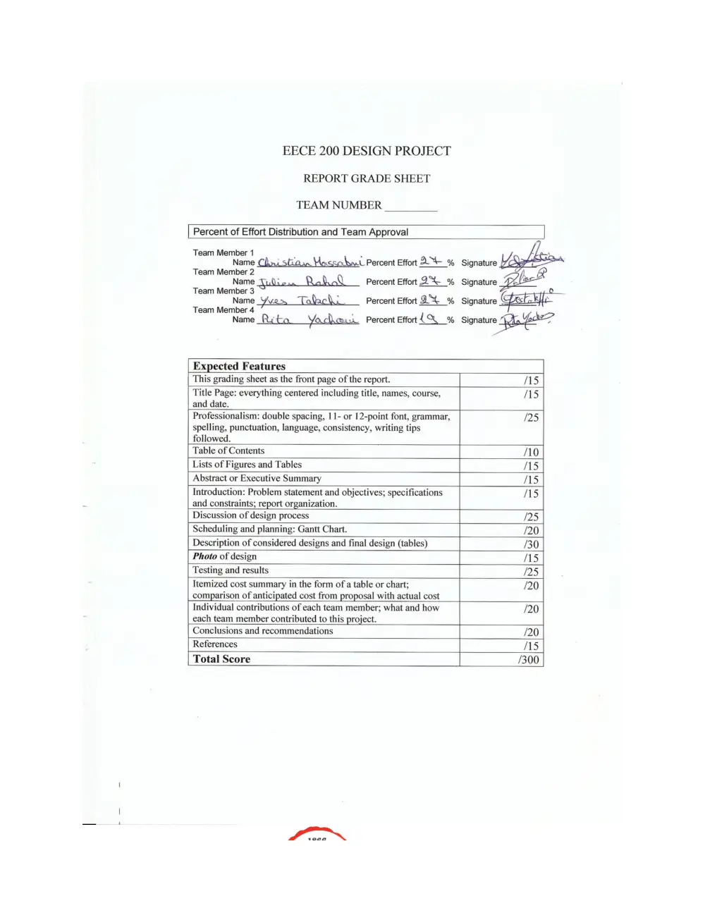
EECE 200 Project Final Report, Fall 2011
American University of Beirut · Introduction to Electrical and Computer Engineering · 23 pages

Showing the first 10 of 23 pages. Download the PDF to see all of it.
More EECE 200 files
- Project Final Presentation · Fall 2011Final examView
- Project Final Report · Fall 2011Final examView
- Project Final Report · Fall 2010Final examView
- Homework 2 · Fall 2014HomeworkView
- Homework 1 · Fall 2014HomeworkView
- Homework 1 Sol · Fall 2014Homework · with solutionView
- Homework 1 with Solution · Fall 2014Homework · with solutionView
- Homework 2 Sol · Fall 2014Homework · with solutionView
Show the text of this final exam
Department of Electrical and Computer
Engineering
EECE 200 – Introduction to Electrical and
Computer Engineering
Design Project Fall 2011-2012
Three-Floor Elevator
- Final Report –
Thursday, January 26th, 2012
Team -11-
Christian Massabni
Julien Rahal
Rita Yachoui
Yves Takchi
Introduction
P
a
g
e
s
1
t
o
6
9
T
a
b
l e
o
f
C
o
n
t
e
n
t
s
Problem Statement
Specifications
Restrictions
Objectives
Report Organization
Work Description
Design Process Discussion
Gantt Chart
Alternative Designs Discussion
Testing conditions and Final Results
Cost Summary
Team Members’ Contribution
Conclusions
References
Appendices
-i-
List of Figures
Fig 1. Hardware overview
Fig 2. Cabin
Fig3. Pulley and small wheels
Fig.4 Lifting System
Fig 5. Door and closing mechanism
Fig6. Door sensor system
Fig 7. Dc fan
Fig. 8 iphone connected to speedy
Fig. 9 Interface Board
Fig. 10 Gantt Chart
Fig. 11 Positioning System
Fig. 12 Door Sensor
Fig. 13 Door System
Fig. 14 Lifting System
-ii-
Anticipated Cost Summary
Final Cost Summary
List of Tables
-iii-
Our aim is to create a functional elevator. Our elevator should go up and down three
floors. It responds to calls made on the different floors and will serve them according to the order
Abstract
in which they are placed. The cabin’s position is permanently indicated on a 7-segment display.
Once the cabin reaches the desired floor, the door opens for 7 seconds. If no obstruction is
detected by the photovoltaic sensor, the door closes automatically after the 7 seconds. Otherwise,
it remains open until the obstruction is cleared. A thermo-sensor is installed inside the cabin.
When this sensor detects an elevation of the ambient temperature, it puts the elevator on
emergency mode. This consists of turning on a dc fan and some red LEDs while turning the
white ones off.
-iv-
Problem Statement
Introduction
The project consisted of programming a 3-floor model elevator, using National Instruments
Labview software, and designing as well its hardware. The program is downloaded to a NI
Speedy-33 DSP board that runs on standalone mode.
This project contributes to a big part of our final grades in EECE 200. Therefore,
for us to pass this course, it is necessary to complete this project.
Specifications
Digital Inputs
Three bump sensors fixed on each floor to indicate the cabin’s position.
Three push buttons on each of the floors to allow the user to call the elevator.
A photo resistor inside the cabin near the door entrance that is constantly hit by a
laser light.
A temperature sensor installed in the cabin.
Analog input
The built in microphones on the speedy 33 board. Three specific tones are
assigned to each level which will allow the program to determine what itinerary to
take.
Digital Outputs :
Two digital outputs to a seven segment display used to display the position of the
elevator.
Three digital outputs that control the motors that opens the doors of each floors.
One digital output controlling the lifting motor.
One digital output controlling the lifting motor's direction.
One digital output that controls a dc fan installed in the elevator.
Restrictions
Since were recently introduced to LabVIEW, we were obliged to do personal researches in order
to overcome some difficulties and weaknesses. Also, the model had to be accomplished and
delivered on time. Moreover, we had to work in a group and try to cope with all the restrictions we
had and limit ourselves to the resources available to us. In fact, we had to do everything on our own,
and hence were constrained to our abilities.
Objectives
This project was assigned to us for different reasons. Its main purpose was to enhance our
LabVIEW programming skills and apply them on a practical application. It’s also intended to
teach us how to figure out solutions to the problems we face. This helped us understanding
the problem solving process. Furthermore, one of the project’s targets is to develop our
ability to work and cooperate in a team of engineers. Finally, the project’s goal was to
familiarize with the design and development of engineering projects.
Report Organization
In this final report concerning our project, we’re going to discuss the whole design process
we went through. We will also represent our time planning in a Gantt chart. Then, we will about
the project.discuss each design alternative, while focusing on the final one. Later, we will analyze
the testing results of the design. In addition, the final cost summary will be compared to the one
anticipated in our proposal. At the end, we will state each member’s contribution to the
completion of this project and the part where he was the most effective. We will then be able to
conclude
Design Process Discussion
Work Description
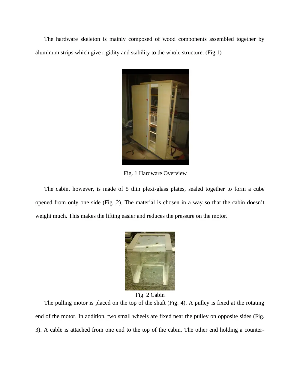
The hardware skeleton is mainly composed of wood components assembled together by
aluminum strips which give rigidity and stability to the whole structure. (Fig.1)
Fig. 1 Hardware Overview
The cabin, however, is made of 5 thin plexi-glass plates, sealed together to form a cube
opened from only one side (Fig .2). The material is chosen in a way so that the cabin doesn’t
weight much. This makes the lifting easier and reduces the pressure on the motor.
Fig. 2 Cabin
The pulling motor is placed on the top of the shaft (Fig. 4). A pulley is fixed at the rotating
end of the motor. In addition, two small wheels are fixed near the pulley on opposite sides (Fig.
3). A cable is attached from one end to the top of the cabin. The other end holding a counter-
weight. The two small wheels were installed in order to reduce and even eliminate the friction
between the cable and the wood.
Fig.3 Pulley and small wheels Fig. 4 Lifting system
3 CD-ROMs fixed at each floor represent the doors. A transparent plastic plate is sealed at
the end of the sliding part of the CD-ROM so that the interior of the cabin is always shown even
when the door is closed.
The motors of the CD-ROMs are only used to open the doors. Therefore, a mechanism should be
constructed to close automatically the doors once the motor has stopped. The mechanism
consists of a metal circular spring fixed between the CD-ROM and the wooden shaft.
Fig. 5 Door and closing mechanism
3 bump sensors are also placed on a vertical rail at each floor in a way that the cabin presses
accurately the sensor corresponding to the floor at which it is.
A laser pointer is fixed at the cabin entrance and hits continuously a photovoltaic resistor
(Fig. 6). If an obstacle prevent the light from reaching the resistor, the door motor remains on
until the obstacle is cleared.
Fig. 6 Door sensor system
In addition, a temperature sensor is installed inside the cabin. If the temperature goes above
the fixed threshold, the cabin goes into an emergency mode: a dc fan is then turned on as well as
some red LEDs.
Fig. 7 dc fan
The cabin can be also called at any of the three floors using a single frequency tone. In
auxiliary cable connects the analog input of Speedy to the output of the iPhone where a tone
simulator is installed.
Fig. 8 iPhone connected to Speedy
All the wires coming out from the different electronic components installed inside the
elevator are connected to an interface board (Fig.9) attached to the Speedy board with a flat
cable.
Fig. 9 Interface Board
Gantt Chart
Planning, Brain Storming & Research
Collecting Different Design Altrnatives
Working on the Proposal
Developping the VI
Collecting Tools and Materials for the Hardware
Building the Hardware Main Parts
Finalising the VI & Testing on Speedy
Adding Extra Features
Testing & Finalising the Hardware
Working on the Presentation
Working on the Final Report
11/16/2011 11/26/2011
12/6/2011
12/16/2011 12/26/2011
1/5/2012
1/15/2012
1/25/2012
Fig. 10 Gantt Chart
Alternative Designs Discussion
First Design
Fig. 11 Positioning System
Three photo resistors are installed on each floor on the inside of the shaft, and
one large radius light bulb is fixed below the elevator cabin (Fig. 11). When the
cabin reaches a level, the light from the light bulb hits the photo resistor and the
sensor circuit is closed, indicating the presence of the cabin on that floor. When no
light hits the sensor the circuit is opened.
Fig. 12 Door Sensor
A single photo resistor is placed in the inside of the cabin with an infrared source
constantly hitting it (Fig. 12). When something obstructs the infrared beam, no
light hits the photo resistor and the circuit is open, preventing the door from
closing.
Fig. 13 Doors System
A motor with gears is attached to the door on each level (Fig. 13), a
command opens half of it with one rotational motion (clockwise) and closes with a
second command that turns it in the opposite rotational motion (counter
clockwise).
Fig. 14 Lifting System
A motor on the top of the shaft pulls and drops a counterweight connected
to the cabin. When the motor isn’t running, the counterweight prevents the cabin
from sliding.
Second Design
The infrared emitter used for the door sensor, is replaced by a laser pointer.
A metal plate is placed underneath the cabin with a piece sticking out, and on
each floor an open circuit that close when the metal piece of the elevator comes in
contact with it, indicating the presence of the elevator on that floor.
Third Design
Bump sensors are places at each floor instead of the photo-resistor.
Anticipated Costs
Cost Summary
inal
Costs Summary
Comparing the effective price with the price we wrote in the proposal, it turns out we paid
slightly more than what we have anticipated on paying. We predicted that we had to pay 714$ but
we paid instead 727$ which is not a big difference.
Article
Quantity
Unit price
Total Price
Speedy 33
1
$600
$600
Big pulling motor
1
$10
$10
Motors for the doors
3
$5
$15
Temperature sensor
1
$2
$2
Photo resistors
Lasers
4
4
$2
$5
$8
$20
LED Lights
6
$1
$6
Cabin + shaft (Aluminum)
Wheels
Pulley + Tracks + Gears
Wiring
1
5
$22
$2
$22
$10
$16
$5
Estimated Total Amount
$714
Article
Quantity
Unit price
Total Price
Speedy 33
1
$600
$600
Big pulling motor
1
$10
$10
CD-ROMs
3
$10
$30
Temperature sensor
1
$2
$2
Photo resistors
Lasers
1
2
$2
$5
$2
$10
LED Lights
6
$1
$6
Wood
Plexi-Glass
Pulley + Tracks + Gears
Wiring
Cutting Fees
2m2
1m2
$8
$15
$16
$15
$16
$10
$10
Estimated Total Amount
$727
Name
Qualifications
Allocated part of the project
Julien Rahal
Great organizational and
cooperative skills. Clear
understanding of the
procedure and project
material. Also has a skill in
illustrating and drawing
sketches.
Assures the complete
interaction between the group
members. Drew the designs
clearly after they have been
presented as essential ideas.
Major role in realizing the
hardware and the final report.
Yves Takchi
Deep understanding of the
material and know-how of the
project realization procedure,
and mastery of the English
writing language.
Presenting the basic ideas
about the project and
knowledge about where to
find each material needed. Did
the initial. Participated in
editing the final draft of the
proposal.
Major role in building the
software and hardware.
Christian Massabni
Very good leadership and
organizational skills. Time
management skills. Basic
understanding of all the
information presented during
group discussions.
Organization of the group
work and control over all the
work done. Time management
for the group. Participated in
editing the final draft of the
proposal.
Major role in building the
software and reports.
Rita Yachoui
Good mastery of the English
Language. Responsible for
typing the proposal report.
Offering creative ideas and
additional aspects and
components for the project.
Doing research on the subject.
Participation in the group
discussions as well as offering
ideas.
Team Members'
Contribution
The project was very useful and had several important benefits.
It taught us how to work in a group and be able to divide the work equally among the group
members. It taught us how to respect the notion of time and deliver all the required before the
deadline. We learned through it how to discover the answers to our problem on our own and face the
challenges as a team. It made us go through all the problem solving steps and prepared us somewhat
for the future.
It was a very important project for us since it was our first and it was our chance to prove
ourselves and show what we’re capable of. It was a very interesting assignment and we enjoyed
working on it and were even more amused with the results. We know now what to expect in the
projects to come and we are now ready to take on the next challenge.
Conclusions
Proposal report:
http://www.ece.rutgers.edu/~marsic/Teaching/SE/proposal.htm
Temperature Sensor
http://www.vernier.com/probes/temperature.html
Photo resistors
http://www.ladyada.net/learn/sensors/cds.html
Creating Gantt Chart
http://www.youtube.com/watch?v=HQwE0Xv1lAA
http://www.youtube.com/watch?v=HQwE0Xv1lAA
http://moodle.aub.edu.lb/course/view.php?id=4260
References