
EECE 210 Exam 1 with Solution, Fall 2011
American University of Beirut · Electric Circuits · 8 pages · with solution


More EECE 210 files
- Exam 1 Fall 2018 Quiz 1 · Fall 2018ExamView
- Exam 2 Fall 2018 Quiz 2 · Fall 2018ExamView
- Exam 2 (Quiz 2) Clean Copy · Fall 2018ExamView
- Exam 1 · Spring 2016ExamView
- Exam PSpice Quiz · Fall 2016ExamView
- Exam 2 · Spring 2016ExamView
- Exam 2 · Spring 2016ExamView
- Exam 2 With Solution · Fall 2016Exam · with solutionView
Show the text of this exam
EECE 210 – Quiz 1
October 22, 2011
1.
The figure shows the assigned voltage drop across a given
circuit element, the current being carried by electrons flowing
through the circuit element in the direction shown. Which of the
following statements is, or are, true? (Note: if a false statement
is marked true, the answer to this Question 1 is considered
incorrect).
A. The circuit element delivers power.
B. The electric potential energy of electrons is higher at terminal a than at terminal b.
C. If the flow of electrons is 3.21019/s, and the charge per electron is -1.610-19 C, the
magnitude of the current is 21038 A.
D. The difference between the electric potential energies of electrons at terminals a and
b is independent of which of these terminals is grounded.
E. If the element is a resistor and power is absorbed by the element, then if the rate of
flow of electrons in particles per second is doubled, the power absorbed by the
element will be doubled.
Answers: A. The direction of conventional current flow is opposite that of electron flow,
because electrons are negatively charged. The current is in the direction of a
voltage drop and power is absorbed by the element.
B. Because of their negative charge, electrons will have a higher electric
potential energy at the more negatively charged terminal, b.
C. The magnitude of the current is 3.210191.610-19 = 5.12 A.
D. The difference in electric potential energy is independent of where the
arbitrary zero of this potential energy is taken.
E. When the rate of flow is doubled, the current is doubled, the voltage drop is
doubled, and the power absorbed is quadrupled.
Only statement D is true.
2.
Which of the following statements is, or are, true of the
1
+
–
v
Direction of
flow of
electrons
a
b
–
+
–
+
5 V
10 V
2 A
1 A
5
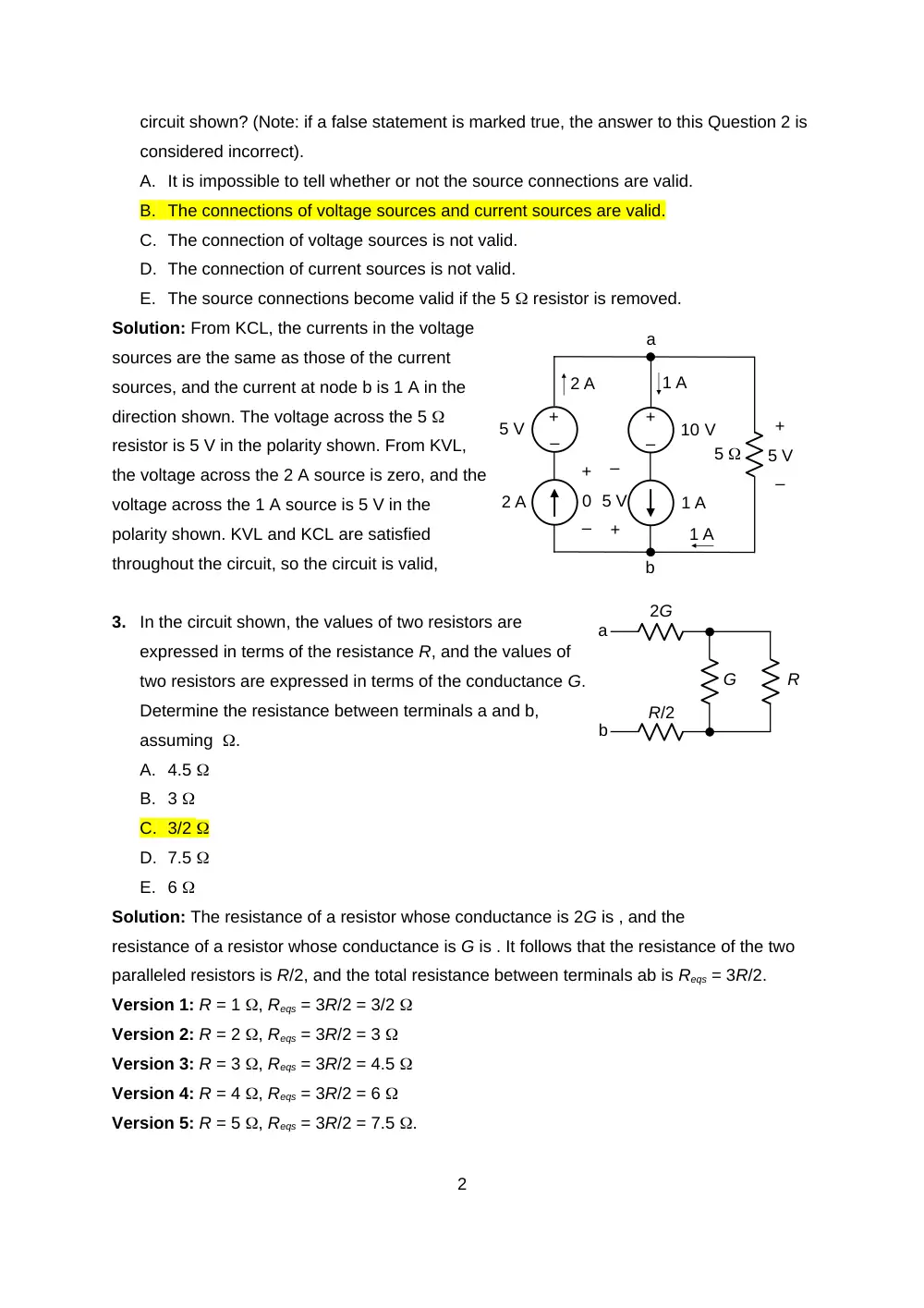
circuit shown? (Note: if a false statement is marked true, the answer to this Question 2 is
considered incorrect).
A. It is impossible to tell whether or not the source connections are valid.
B. The connections of voltage sources and current sources are valid.
C. The connection of voltage sources is not valid.
D. The connection of current sources is not valid.
E. The source connections become valid if the 5 resistor is removed.
Solution: From KCL, the currents in the voltage
sources are the same as those of the current
sources, and the current at node b is 1 A in the
direction shown. The voltage across the 5
resistor is 5 V in the polarity shown. From KVL,
the voltage across the 2 A source is zero, and the
voltage across the 1 A source is 5 V in the
polarity shown. KVL and KCL are satisfied
throughout the circuit, so the circuit is valid,
3.
In the circuit shown, the values of two resistors are
expressed in terms of the resistance R, and the values of
two resistors are expressed in terms of the conductance G.
Determine the resistance between terminals a and b,
assuming .
A. 4.5
B. 3
C. 3/2
D. 7.5
E. 6
Solution: The resistance of a resistor whose conductance is 2G is , and the
resistance of a resistor whose conductance is G is . It follows that the resistance of the two
paralleled resistors is R/2, and the total resistance between terminals ab is Reqs = 3R/2.
Version 1: R = 1 , Reqs = 3R/2 = 3/2
Version 2: R = 2 , Reqs = 3R/2 = 3
Version 3: R = 3 , Reqs = 3R/2 = 4.5
Version 4: R = 4 , Reqs = 3R/2 = 6
Version 5: R = 5 , Reqs = 3R/2 = 7.5 .
2
–
+
–
+
5 V
10 V
2 A
1 A
5
a
b
1 A
–
+
5 V
–
+
0
–
+
5 V
2 A
1 A
2G
R/2
G
a
b
R
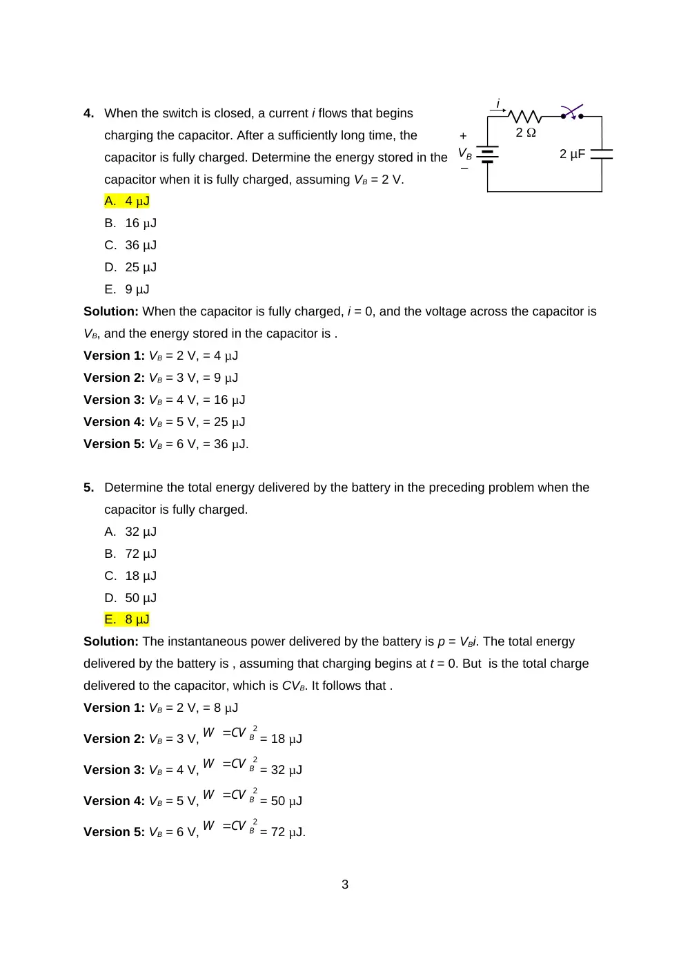
4.
When the switch is closed, a current i flows that begins
charging the capacitor. After a sufficiently long time, the
capacitor is fully charged. Determine the energy stored in the
capacitor when it is fully charged, assuming VB = 2 V.
A. 4 µJ
B. 16 µJ
C. 36 µJ
D. 25 µJ
E. 9 µJ
Solution: When the capacitor is fully charged, i = 0, and the voltage across the capacitor is
VB, and the energy stored in the capacitor is .
Version 1: VB = 2 V, = 4 µJ
Version 2: VB = 3 V, = 9 µJ
Version 3: VB = 4 V, = 16 µJ
Version 4: VB = 5 V, = 25 µJ
Version 5: VB = 6 V, = 36 µJ.
5.
Determine the total energy delivered by the battery in the preceding problem when the
capacitor is fully charged.
A. 32 µJ
B. 72 µJ
C. 18 µJ
D. 50 µJ
E. 8 µJ
Solution: The instantaneous power delivered by the battery is p = VBi. The total energy
delivered by the battery is , assuming that charging begins at t = 0. But is the total charge
delivered to the capacitor, which is CVB. It follows that .
Version 1: VB = 2 V, = 8 µJ
Version 2: VB = 3 V,
= 18 µJ
Version 3: VB = 4 V,
= 32 µJ
Version 4: VB = 5 V,
= 50 µJ
Version 5: VB = 6 V,
= 72 µJ.
3
+
–
VB
2
2 µF
i
CV B2
W
CV B2
W
CV B2
W
W CV B2
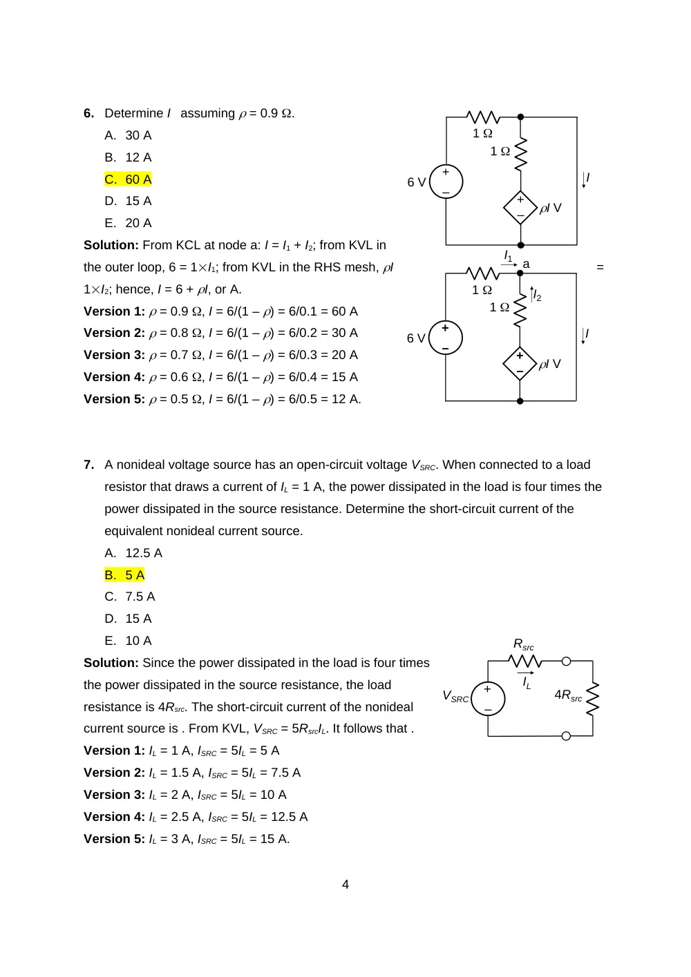
6.
Determine I assuming = 0.9 .
A. 30 A
B. 12 A
C. 60 A
D. 15 A
E. 20 A
Solution: From KCL at node a: I = I1 + I2; from KVL in
the outer loop, 6 = 1I1; from KVL in the RHS mesh, I
=
1I2; hence, I = 6 + I, or A.
Version 1: = 0.9 , I = 6/(1 – ) = 6/0.1 = 60 A
Version 2: = 0.8 , I = 6/(1 – ) = 6/0.2 = 30 A
Version 3: = 0.7 , I = 6/(1 – ) = 6/0.3 = 20 A
Version 4: = 0.6 , I = 6/(1 – ) = 6/0.4 = 15 A
Version 5: = 0.5 , I = 6/(1 – ) = 6/0.5 = 12 A.
7.
A nonideal voltage source has an open-circuit voltage VSRC. When connected to a load
resistor that draws a current of IL = 1 A, the power dissipated in the load is four times the
power dissipated in the source resistance. Determine the short-circuit current of the
equivalent nonideal current source.
A. 12.5 A
B. 5 A
C. 7.5 A
D. 15 A
E. 10 A
Solution: Since the power dissipated in the load is four times
the power dissipated in the source resistance, the load
resistance is 4Rsrc. The short-circuit current of the nonideal
current source is . From KVL, VSRC = 5RsrcIL. It follows that .
Version 1: IL = 1 A, ISRC = 5IL = 5 A
Version 2: IL = 1.5 A, ISRC = 5IL = 7.5 A
Version 3: IL = 2 A, ISRC = 5IL = 10 A
Version 4: IL = 2.5 A, ISRC = 5IL = 12.5 A
Version 5: IL = 3 A, ISRC = 5IL = 15 A.
4
–
+
–
+
I
6 V
1
1
I V
–
+
–
+
I
6 V
1
1
I V
I1
I2
a
–
+
VSRC
IL
Rsrc
4Rsrc
8.
Determine the energy stored in the inductor if L = 1 H
assuming dc conditions, after all voltages and currents
have assumed constant values.
A. 0.75 J
B. 1 J
C. 1.5 J
D. 2 J
E. 0.5 J
Solution: Under dc conditions, the current through the capacitors is zero, and the voltage
across the inductor is zero. From KVL, a current equal to 1A passes through the
upper 5 resistor and through L. The energy stored in the inductor is = L/2 J.
Version 1: L = 1 H, W = L/2 = 0.5 J
Version 2: L = 1.5 H, W = L/2 = 0.75 J
Version 3: L = 2 H, W = L/2 = 1 J
Version 4: L = 3 H, W = L/2 = 1.5 J
Version 5: L = 4 H, W = L/2 = 2 J.
9.
Determine VX, assuming VSRC = 2.5 V.
A. 1 V
B. 5 V
C. 3 V
D. 2 V
E. 4 V
Solution: From KVL, VSRC = 3I + Vx = 5I; I = VSRC/5, and VX = 2VSRC/5 = 0.4VSRC.
Version 1: VSRC = 2.5 V, VX = 0.4VSRC = 1 V
Version 2: VSRC = 5 V, VX = 0.4VSRC = 2 V
Version 3: VSRC = 7.5 V, VX = 0.4VSRC = 3 V
Version 4: VSRC = 10 V, VX = 0.4VSRC = 4 V
Version 5: VSRC = 12.5 V, VX = 0.4VSRC = 5 V.
10. The figure shows the variation with time of the
charge across a capacitor of 0.1 µF. Determine the
average voltage across the capacitor.
A. V
5
–
+
5 V
5
1 µF
5
L
–
+
VSRC
I
3
–
+
2I
–
+
VX
min
q C
4
4
6
-2
B. 2.5 V
C. 2 V
D. 10 V
E. 5 V
Solution: The net area is C-min. The average charge is 6/6 = 1C and the average
voltage is V = (1C)/(C F) = 1/C V.
Version 1: C = 0.1 F, V = 1/C = 10 V
Version 2: C = 0.2 F, V = 1/C = 5 V
Version 3: C = 0.4 F, V = 1/C = 2.5 V
Version 4: C = 0.5 F, V = 1/C = 2 V
Version 5: C = 0.8 F, V = 1/C = 1.25 V.
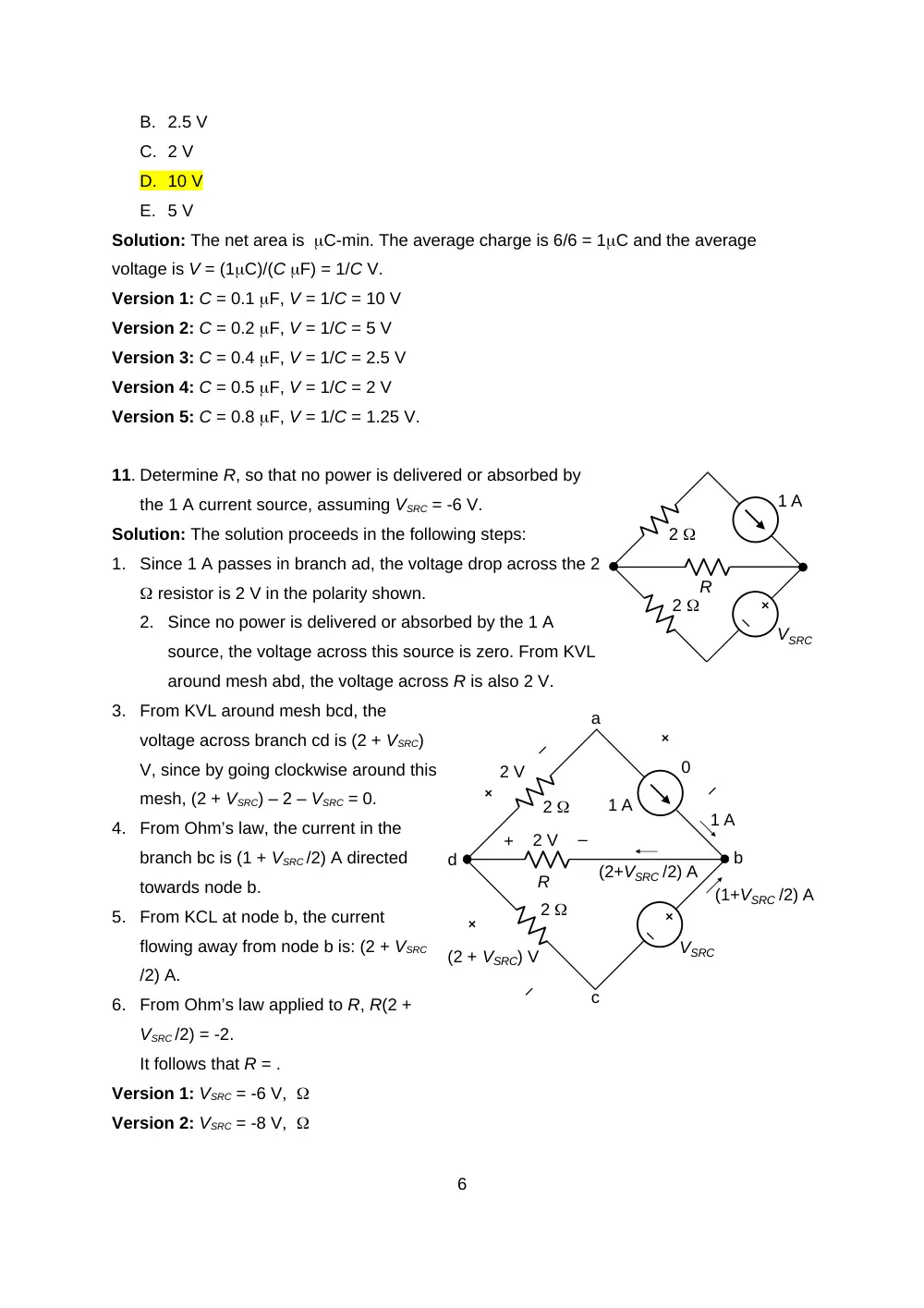
11. Determine R, so that no power is delivered or absorbed by
the 1 A current source, assuming VSRC = -6 V.
Solution: The solution proceeds in the following steps:
1.
Since 1 A passes in branch ad, the voltage drop across the 2
resistor is 2 V in the polarity shown.
2.
Since no power is delivered or absorbed by the 1 A
source, the voltage across this source is zero. From KVL
around mesh abd, the voltage across R is also 2 V.
3.
From KVL around mesh bcd, the
voltage across branch cd is (2 + VSRC)
V, since by going clockwise around this
mesh, (2 + VSRC) – 2 – VSRC = 0.
4.
From Ohm’s law, the current in the
branch bc is (1 + VSRC /2) A directed
towards node b.
5.
From KCL at node b, the current
flowing away from node b is: (2 + VSRC
/2) A.
6.
From Ohm’s law applied to R, R(2 +
VSRC /2) = -2.
It follows that R = .
Version 1: VSRC = -6 V,
Version 2: VSRC = -8 V,
6
1 A
VSRC
2
2
R
a
b
d
c
1 A
VSRC
2
2
R
1 A
2 V
+
–
2 V
(2 + VSRC) V
(1+VSRC /2) A
(2+VSRC /2) A
0
Version 3: VSRC = -10 V,
Version 4: VSRC = -12 V,
Version 5: VSRC = -14 V, .
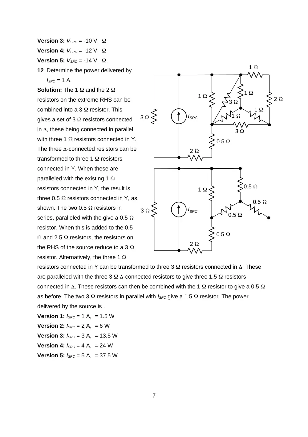
12. Determine the power delivered by
ISRC = 1 A.
Solution: The 1 and the 2
resistors on the extreme RHS can be
combined into a 3 resistor. This
gives a set of 3 resistors connected
in , these being connected in parallel
with three 1 resistors connected in Y.
The three -connected resistors can be
transformed to three 1 resistors
connected in Y. When these are
paralleled with the existing 1
resistors connected in Y, the result is
three 0.5 resistors connected in Y, as
shown. The two 0.5 resistors in
series, paralleled with the give a 0.5
resistor. When this is added to the 0.5
and 2.5 resistors, the resistors on
the RHS of the source reduce to a 3
resistor. Alternatively, the three 1
resistors connected in Y can be transformed to three 3 resistors connected in . These
are paralleled with the three 3 -connected resistors to give three 1.5 resistors
connected in . These resistors can then be combined with the 1 resistor to give a 0.5
as before. The two 3 resistors in parallel with ISRC give a 1.5 resistor. The power
delivered by the source is .
Version 1: ISRC = 1 A, = 1.5 W
Version 2: ISRC = 2 A, = 6 W
Version 3: ISRC = 3 A, = 13.5 W
Version 4: ISRC = 4 A, = 24 W
Version 5: ISRC = 5 A, = 37.5 W.
7
2
1
1
1
1
1
3
3
2
0.5
3
ISRC
0.5
1
2
0.5
3
ISRC
0.5
0.5
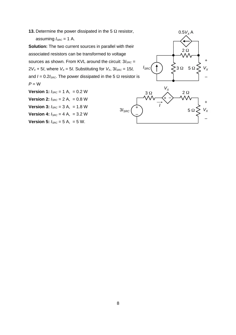
13. Determine the power dissipated in the 5 resistor,
assuming ISRC = 1 A.
Solution: The two current sources in parallel with their
associated resistors can be transformed to voltage
sources as shown. From KVL around the circuit: 3ISRC =
2VX + 5I, where VX = 5I. Substituting for VX, 3ISRC = 15I,
and I = 0.2ISRC. The power dissipated in the 5 resistor is
P = W
Version 1: ISRC = 1 A, = 0.2 W
Version 2: ISRC = 2 A, = 0.8 W
Version 3: ISRC = 3 A, = 1.8 W
Version 4: ISRC = 4 A, = 3.2 W
Version 5: ISRC = 5 A, = 5 W.
8
3
2
ISRC
5
0.5VX A
–
+
VX
–
+
–
+
–
+
VX
3
2
5
VX
3ISRC
I