
EECE 210 Exam 2, Fall 2000
American University of Beirut · Electric Circuits · 6 pages
More EECE 210 files
- Exam 1 Fall 2018 Quiz 1 · Fall 2018ExamView
- Exam 2 Fall 2018 Quiz 2 · Fall 2018ExamView
- Exam 2 (Quiz 2) Clean Copy · Fall 2018ExamView
- Exam 1 · Spring 2016ExamView
- Exam PSpice Quiz · Fall 2016ExamView
- Exam 2 · Spring 2016ExamView
- Exam 2 · Spring 2016ExamView
- Exam 2 With Solution · Fall 2016Exam · with solutionView
Show the text of this exam
www.amal-aub.org
Profs, N. Sabah FACULTY OF ENGINEERING FALL TERM 2¢
R. Chedid & ARCHITECTURE
L. Chaar
i. Mougharbel
NOV’ , 20
=]
={
Ww
“sj
ea
se]
NS
>
>
oS
(ELEG 310) ELECTRIC CIRCUITS
CLOSED BOOK (1% HRS)
Programmable Calculators are not allowed
Provide your answers on the computer’s card only
Return the computer’s card attached to the question sheet
Mark with a pencil your name and your ID-No
Use pencil for marking your answers
When using eraser, be sure that you have erased well
it PENALTY IS6 TO t
Test ID 2000- 1/5
www.amal-aub.org
Profs. N. Sabah FACULTY OF ENGINEERING
R. Chedid & ARCHITECTURE
iL. Chaar
I. Mougharbel
(ELEG 310) ELECTRIC CIRCUITS
CLOSED BOOK (1 % HRS)
Programmable Calculators are not allowed
Provide your answers on the computer’s card only
Return the computer’s card attached to the question sheet
Mark with a pencil your name and your ID-No
Use pencil for marking your answers
When using eraser, be sure that you have erased well
it! PENALTY IS6TO1
Mm!
FALL TERM 2¢
NOV ,20
Test ID 2000- 1/5
www.amal-aub.org
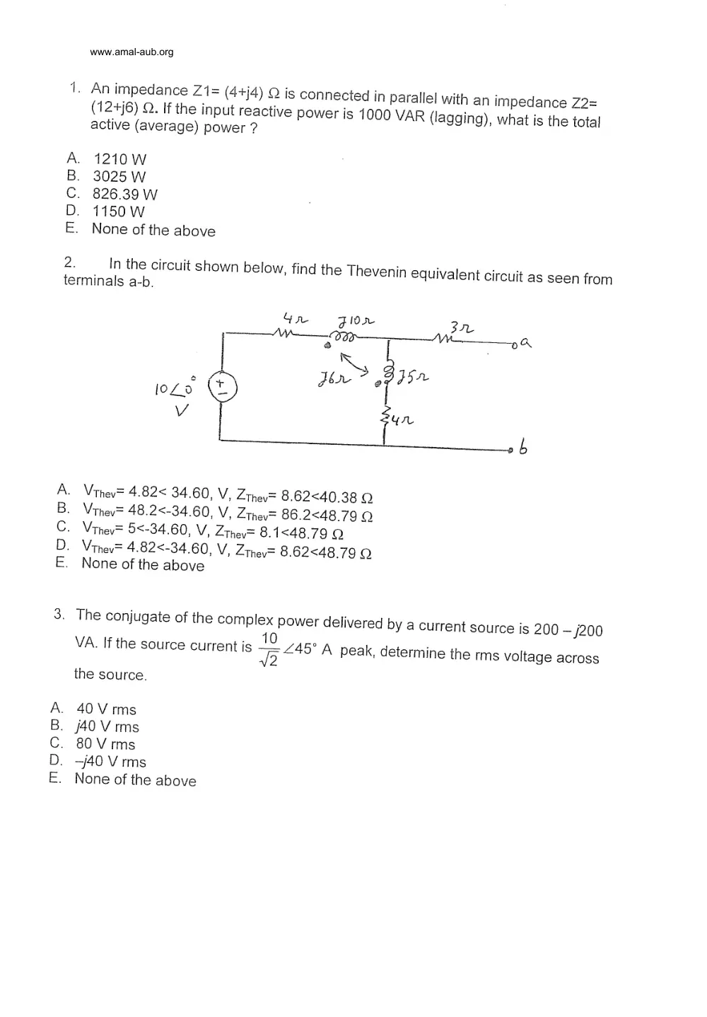
1. An impedance Z1= (4+)4) Q is connected in parallel with an impedance Z2=
(12+)6) ©. If the input reactive power is 1000 VAR (lagging), what is the total
active (average) power ?
A. 1210 W
B. 3025 Ww
C. 826.39 W
D. 1150 W
E. None of the above
2. In the circuit shown below, find the Thevenin equivalent circuit as seen from
terminals a-b.
Gre Flo Pr
WW {at— ae AN
o a phe > ‘Bose
jogo (e |
V i
ab
Vrhev= 4.82< 34.60, V, Zthev= 8.62<40.38 Q
Vthev= 48.2<-34.60, V, Zthev= 86.2<48.79 Q
Vrhev= 5<-34.60, V, Zthev= 8.1<48.79 Q
Vthev= 4.82<-34.60, V, Zthev= 8.62<48.79 Q
None of the above
MOOm>
3. The conjugate of the complex power delivered by a current source is 200 ~/200
VA. If the source current is 88 A peak, determine the rms voltage across
the source.
40 Vrms
/40 V rms
80 V rms
—j40 V rms
None of the above
MOOD
www.amal-aub.org
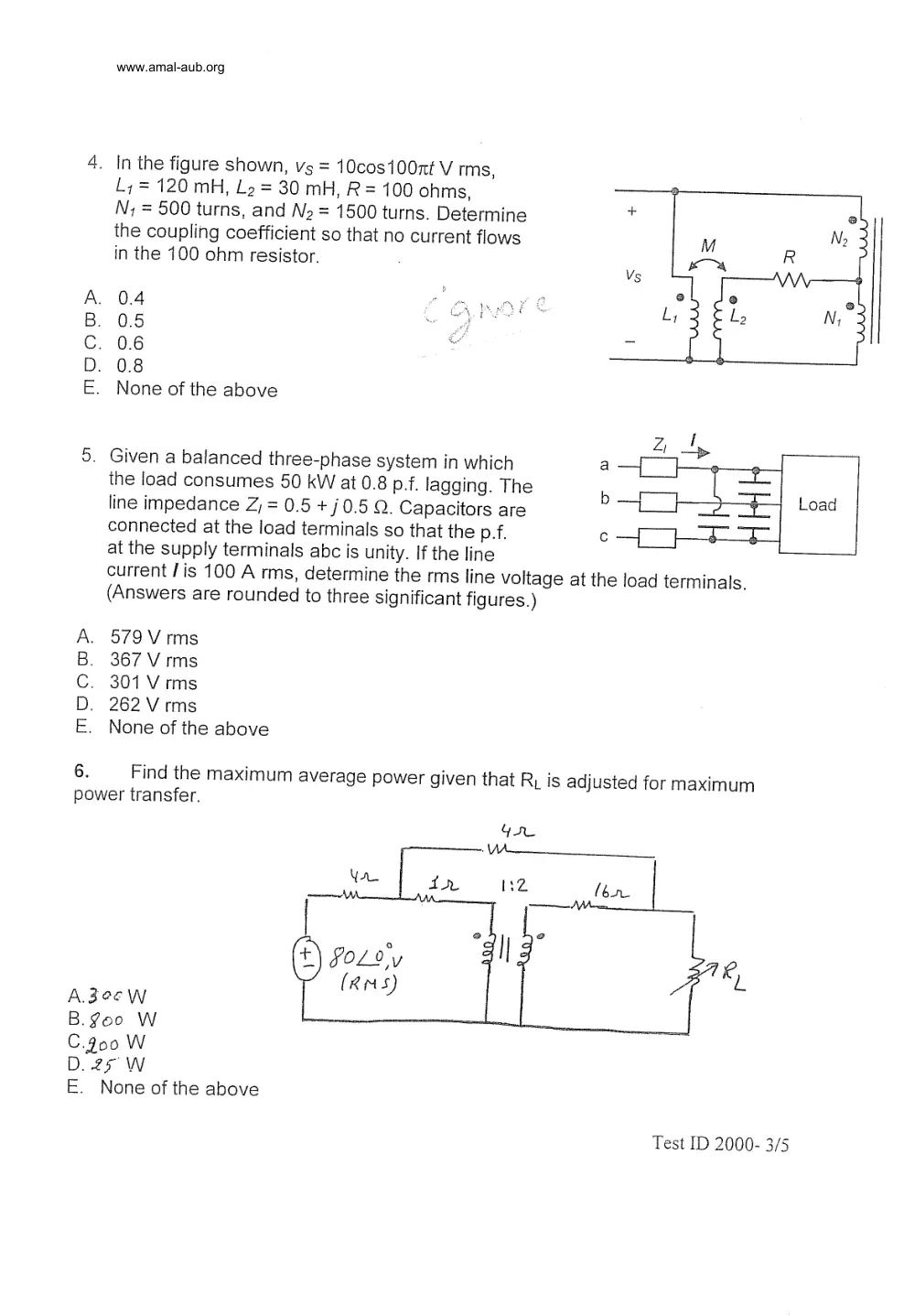
4. In the figure shown, vs = 10cos100nt V rms,
>
L1= 120 mH, Lo = 30 mH, R= 100 ohms,
N; = 500 turns, and Nz = 1500 turns. Determine +
the coupling coefficient so that no current flows M R No
in the 100 ohm resistor. ; Vs =" NA,
. wea e )
A. 0.4 CA PIOES Lr 2 EL, Ny
B. 0.5 a: _
C. 0.6 ~
D. 0.8
E. None of the above
Zz ty
5. Given a balanced three-phase system in which a a
the load consumes 50 kW at 0.8 p.f. lagging. The b lL TI} boad
line impedance Z, = 0.5 + / 0.5 Q. Capacitors are ee aa on
connected at the load terminals so that the p.f. c oe a
at the supply terminals abc is unity. If the line
current / is 100 A rms, determine the rms line voltage at the load terminals.
(Answers are rounded to three significant figures.)
A. 579V rms
B. 367 Vrms
C. 301 Vrms
D. 262 Vrms
E. None of the above
6. Find the maximum average power given that R, is adjusted for maximum
power transfer.
A.3e6W
B. goo W
C.900 W
D. 25 W
E. None of the above
Test ID 2000- 3/5
www.amal-aub.org
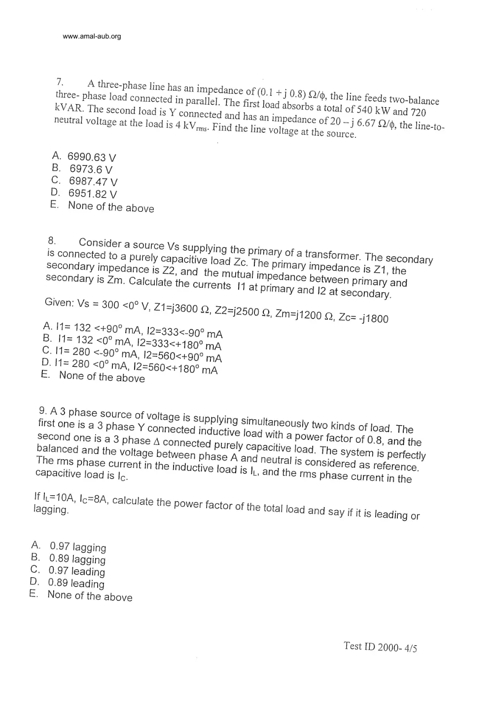
7. A three-phase line has an impedance of (0.1 +] 0.8) £2/, the line feeds two-balance
three- phase load connected in parallel. The first load absorbs a total of 540 kW and 720
KVAR. The second load is Y connected and has an impedance of 20 ~—] 6.67 Q/6, the line-to-
neutral voltage at the load is 4 KV ims. Find the line voltage at the source.
. 6990.63 V
6973.6 V
6987.47 V
6951.82 V
None of the above
MOoOm>s
Given: Vs = 300 <0° V, Z1=j3600 Q, Z2=j2500 Q, Zm=j1200 Q, Zc= -}1800
A. I1= 132 <+99° mA, 12=333<-90° mA
B. I1= 132 <9° MA, 12=333<+189° mA
C. I1= 280 <-g9° MA, 12=560<+90° mA
D. I1= 280 <9? MA, 12=560<+180° mA
E. None of the above
A. 0.97 lagging
B. 0.89 lagging
C. 0.97 leading
D. 0.89 leading
E. None of the above
Test ID 2000- 4/5
www.amal-aub.org
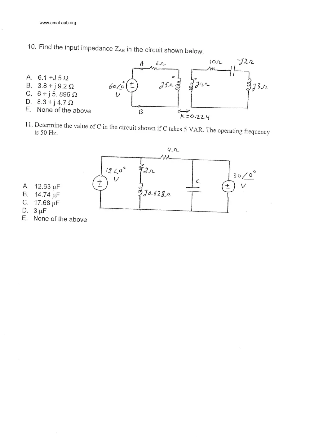
10. Find the input impedance Zag in the circuit shown below.
(or Jar
A ban
oe MM.
Raa y
A. 6.14+35Q : *
B. 38+j920 G0L0 da” ae Jor
C. 6+j5.8969 v
D. 83+j479 e
E. None of the above gB “K20.224
11. Determine the value of C in the circuit shown if C takes 5 VAR. The operating frequency
is 50 Hz.
Gu
VA.
(220° SL 30/0
Vv cam Vv
A. 12.63 uF Q
62
B. 14.74 uF J°-628.2
C. 17.68 uF _
D. 3 uF
E. None of the above