
EECE 210 Exam 2, Fall 2004
American University of Beirut · Electric Circuits · 5 pages
More EECE 210 files
- Exam 1 Fall 2018 Quiz 1 · Fall 2018ExamView
- Exam 2 Fall 2018 Quiz 2 · Fall 2018ExamView
- Exam 2 (Quiz 2) Clean Copy · Fall 2018ExamView
- Exam 1 · Spring 2016ExamView
- Exam PSpice Quiz · Fall 2016ExamView
- Exam 2 · Spring 2016ExamView
- Exam 2 · Spring 2016ExamView
- Exam 2 With Solution · Fall 2016Exam · with solutionView
Show the text of this exam
AMERICAN UNIVERSITY OF BEIRUT
Department of Electrical and Computer Engineering
EECE210 Fall 2004
Quiz 2, December 15, 2004
Prof Karameh
Directions:
- NO PROGRAMMABLE CALCULATORS ARE ALLOWED.
- You will have 1.5 hrs for this quiz.
- Write down your initials in ink on all the pages. DO IT NOW!
- Answers must be explained or derived. DO NOT just write down an answer.
- It is a good idea to read the whole test before you begin. Some problems are divided into
several parts with percentages indicated.
You might be able to solve different parts
independently.
- DO NOT talk to any of your colleagues under any circumstances. You will be penalized
without warning.
YOUR NAME HERE:
EECE210 - Quiz 2- Fall 2004.
NAME:
PROBLEM 1
(15%)
Consider the network shown in figure 1. The Switch was at the 20 Ω for a long time for
t < 0. At t=0, switch is moved to the 10 Ω resistor.
(a) (12 %) Find the current in the inductor iL(t), t ≥ 0.
(b) (3 %) Find the maximum energy stored in the inductor.
−
i (t)
L
.
20 Ω
Ω
Ω
Ω
0.1 H
2.5
5
100 V
+
t=0
.
.
.
15
Figure 1: Problem 1
PROBLEM 2
(12%)
Consider the network shown in figure 2. Find the values of resistors R1, R3 so that the
current supplied by the voltage source Vs is zero for all time. All op-amps are ideal.
R1
Ω
K
Ω
K
Ω
K
Ω
K
Ω
K
Ω
K
Vs
R3
.
_
+
+
_
40
10
5
10
15
30
+
_
.
.
.
.
.
.
.
Figure 2: Problem 2
EECE210 - Quiz 2- Fall 2004.
NAME:
PROBLEM 3
(18%)
Consider the network shown in figure 3.
(a) (4%) Write the differential equations necessary to compute the voltage in the resistor R
for any source voltage v(t).
(b) (4%) If v(t) = 12 − 201e−t, which, if any, of the following currents might actually have
came from the circuit?
(1) i1(t) = 0.24 − 2e−t, i2(t) = 4e−t.
(2) i1(t) = 0.12 − 4e−t, i2(t) = 3e−t.
(3) i1(t) = 0.24 − 4e−t, i2(t) = 3e−t.
(c) (10%) Find the Thevenin equivalent circuit for the network to the left of terminals a,b of
the resistor. (v(t) = 100cos100t volts).
−
.
.
.
+
50 Ω
2 H
5 H
3 H
100 cos(100t) V
a
b
v(t)=
.
.
R=1Ω
i (t)
i (t)
2
1
Figure 3: Problem 3
Problem 4
(15%)
Find the output voltages v1 and v2 of the ideal op-amps shown in figure 4.
Ω
K
Ω
K
Ω
K
Ω
K
Ω
K
2
v
v1
Ω
K
.
+_
_+
.
.
.
.
.
+
+
8 V
12 V
2
2
4
1
2
0.2
Figure 4: Problem 4
EECE210 - Quiz 2- Fall 2004.
NAME:
PROBLEM 5
(20%)
For the network shown in figure 5, find the current i2(t). Show all your work.
i (t)
2
.
Ω
Ω
1Ω
1
0.67 I1
I1
1
1Ω
5sin2t
+
+
1 Amps
volts
.
.
.
.
.
1 H
1 F
Figure 5: Problem 5
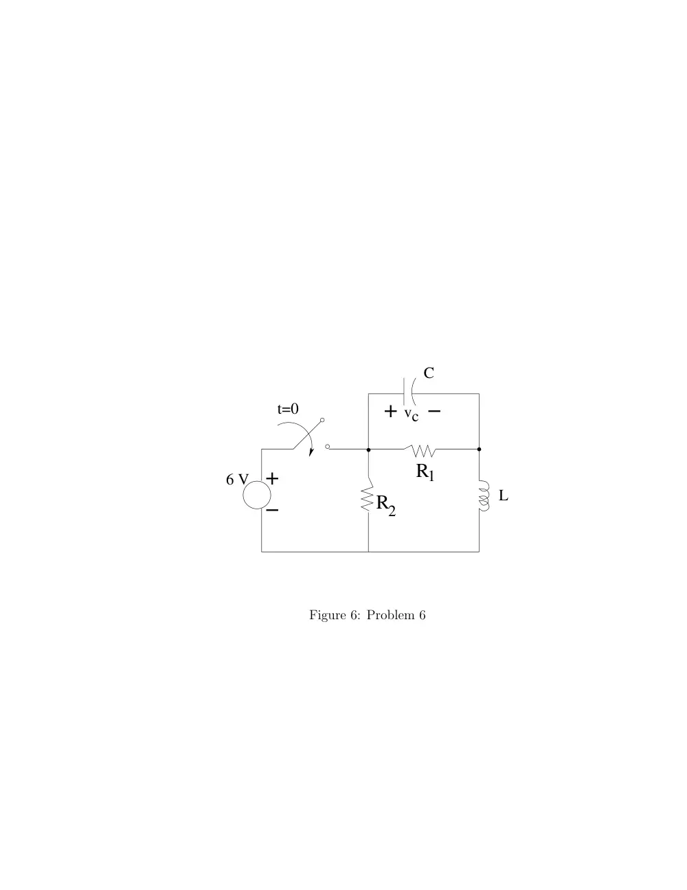
PROBLEM 6
(20%)
Consider the circuit shown in figure 6 below. The switch was open for a very long time
t < 0. At t=0, switch is closed.
(a) (12 %) Given:
L=5 H, C=4 F, R1 = 3Ω, and R2 = 2Ω. Find the voltage in the capacitor
vc(t) for t ≥ 0.
(b) (3 %) Is the circuit response you obtained in part (a) underdamped, critically damped, or
overdamped? explain.
(c) (5 %) If L= 5 H, C=4 F, find R1, R2 such that the circuit response is critically damped.
−
vc −
R
.
+
1
R2
L
C
t=0
6 V
+
.
.
Figure 6: Problem 6