
EECE 210 Exam 2 with Solution, Fall 2010
American University of Beirut · Electric Circuits · 6 pages · with solution

More EECE 210 files
- Exam 1 Fall 2018 Quiz 1 · Fall 2018ExamView
- Exam 2 Fall 2018 Quiz 2 · Fall 2018ExamView
- Exam 2 (Quiz 2) Clean Copy · Fall 2018ExamView
- Exam 1 · Spring 2016ExamView
- Exam PSpice Quiz · Fall 2016ExamView
- Exam 2 · Spring 2016ExamView
- Exam 2 · Spring 2016ExamView
- Exam 2 With Solution · Fall 2016Exam · with solutionView
Show the text of this exam
EECE 210
Quiz 2 – Nov 20, 2010
4%
1. The current components in a resistor R, as found from superposition, are -8 A and +4 A.
Determine the power dissipated in the resistor if R = 2 Ω.
Solution: The magnitude of the current through R is 4 A. The power dissipated in R is 16R.
Version 1: R = 2 Ω, P = 16R = 32 W
Version 2: R = 3 Ω, P = 16R = 48 W
Version 3: R = 4 Ω, P = 16R = 64 W
Version 4: R = 5 Ω, P = 16R = 80 W
Version 5: R = 6 Ω, P = 16R = 96 W.
4%
1
2. Determine IO if VS = 1 V.
Solution: The two terminals
of the 5 Ω resistor are at the
same voltage. Hence, this
resistor carries no current and
can be removed. The 1 Ω in
series with VS can be split into
two parallel branches, each of
2 Ω in series with VS. The
circuit can then be split into two halves as shown. It
follows that
4
5
S
O
V
I
−
=
A.
–
+
5 V
–
+
–
+
5 V
VS
4 Ω
4 Ω
1 Ω
2 Ω
2 Ω
5 Ω
IO
–
+
–
+
5 V
VS
4 Ω
2 Ω
2 Ω
IO
Version 1: VS = 1 V,
1
4
1
5
=
−
=
OI
A
Version 2: VS = 2 V,
0.75
4
2
5
=
−
=
OI
A
Version 3: VS = 3 V,
0.5
4
3
5
=
−
=
OI
A
Version 4: VS = 4 V,
0.25
4
4
5
=
−
=
OI
A
Version 5: VS = 5 V,
0
4
5
5
=
−
=
OI
A.
4%
10 Ω
5 Ω
ISRC
–
+
αISRC
a
b
R
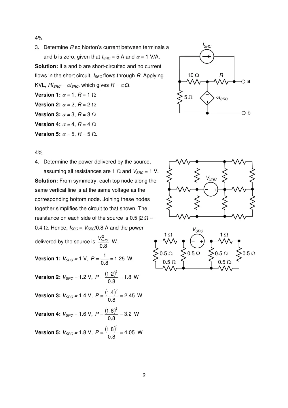
3. Determine R so Norton’s current between terminals a
and b is zero, given that ISRC = 5 A and α = 1 V/A.
Solution: If a and b are short-circuited and no current
flows in the short circuit, ISRC flows through R. Applying
KVL, RISRC = αISRC, which gives R = α Ω.
Version 1: α = 1, R = 1 Ω
Version 2: α = 2, R = 2 Ω
Version 3: α = 3, R = 3 Ω
Version 4: α = 4, R = 4 Ω
Version 5: α = 5, R = 5 Ω.
4%
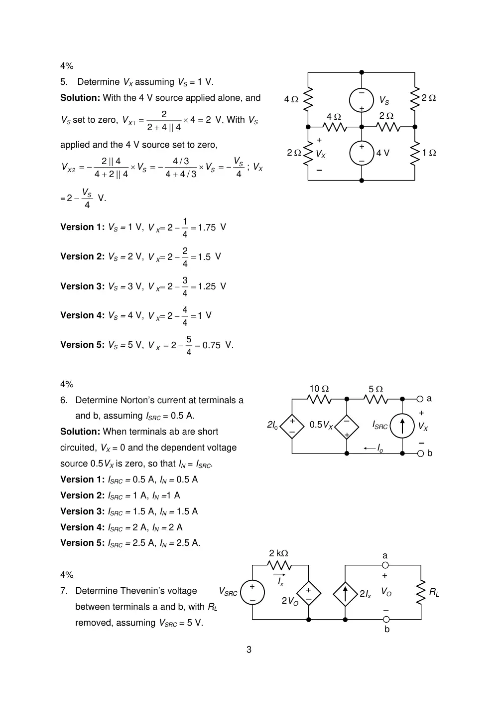
4. Determine the power delivered by the source,
assuming all resistances are 1 Ω and VSRC = 1 V.
–
+
VSRC
2
er
Solution: From symmetry, each top node along the
same vertical line is at the same voltage as the
corresponding bottom node. Joining these nodes
together simplifies the circuit to that shown. The
resistance on each side of the source is 0.5||2 Ω =
0.4 Ω. Hence, ISRC = VSRC/0.8 A and the pow
delivered by the source is
.8
0
2
VSRC
W.
–
+
VSRC
1 Ω
1 Ω
0.5 Ω
0.5 Ω
0.5 Ω
0.5 Ω
0.5 Ω
0.5 Ω
Version 1: VSRC = 1 V,
1.25
0.8
1 =
P =
W
Version 2: VSRC = 1.2 V,
(
)
1.8
0.8
1.2
2
=
P =
W
Version 3: VSRC = 1.4 V,
(
)
2.45
0.8
1.4
2
=
P =
W
Version 4: VSRC = 1.6 V,
(
)
3.2
0.8
1.6
2
=
P =
W
Version 5: VSRC = 1.8 V,
(
)
4.05
0.8
1.8
2
=
P =
W
4%
–
+
2 Ω
2 Ω
4 Ω
4 Ω
1 Ω
–
+
2 Ω
4 V
VS
+
–
VX
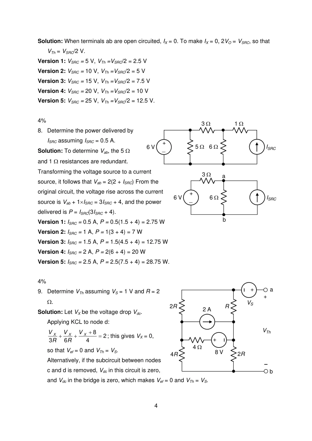
5. Determine VX assuming VS = 1 V.
Solution: With the 4 V source applied alone, and
VS set to zero,
2
4
4 || 4
2
2
1
=
×
+
VX =
V. With VS
applied and the 4 V source set to zero,
4
4 / 3
4
4 / 3
2 || 4
4
2 || 4
2
S
S
S
X
V
V
V
V
= −
×
+
= −
×
+
= −
; VX
=
4
2
− VS
V.
Version 1: VS = 1 V,
1.75
4
1
2
=
−
V X=
V
Version 2: VS = 2 V,
1.5
4
2
2
=
−
V X=
V
Version 3: VS = 3 V,
1.25
4
3
2
=
−
V X=
V
Version 4: VS = 4 V,
1
4
4
2
=
−
V X=
V
Version 5: VS = 5 V,
0.75
4
5
2
=
−
V X =
V.
4%
ISRC
–
+
0.5VX
–
+
5 Ω
10 Ω
2Io
Io
a
b
+
–
VX
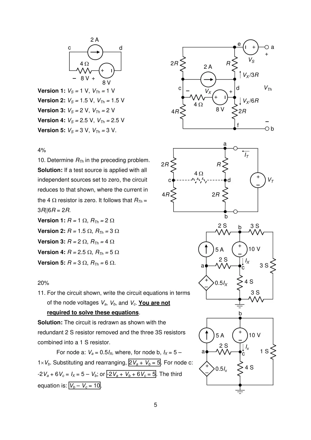
6. Determine Norton’s current at terminals a
and b, assuming ISRC = 0.5 A.
Solution: When terminals ab are short
circuited, VX = 0 and the dependent voltage
source 0.5VX is zero, so that IN = ISRC.
Version 1: ISRC = 0.5 A, IN = 0.5 A
Version 2: ISRC = 1 A, IN =1 A
Version 3: ISRC = 1.5 A, IN = 1.5 A
Version 4: ISRC = 2 A, IN = 2 A
Version 5: ISRC = 2.5 A, IN = 2.5 A.
2 kΩ
3
–
+
VSRC
–
+
+
–
a
b
4%
2Ix
2VO
RL
Ix
VO
7. Determine Thevenin’s voltage
between terminals a and b, with RL
removed, assuming VSRC = 5 V.
Solution: When terminals ab are open circuited, IX = 0. To make IX = 0, 2VO = VSRC, so that
VTh = VSRC/2 V.
Version 1: VSRC = 5 V, VTh =VSRC/2 = 2.5 V
Version 2: VSRC = 10 V, VTh =VSRC/2 = 5 V
Version 3: VSRC = 15 V, VTh =VSRC/2 = 7.5 V
Version 4: VSRC = 20 V, VTh =VSRC/2 = 10 V
Version 5: VSRC = 25 V, VTh =VSRC/2 = 12.5 V.
4%
4
8. Determine the power delivered by
ISRC assuming ISRC = 0.5 A.
Solution: To determine Vab, the 5 Ω
and 1 Ω resistances are redundant.
Transforming the voltage source to a current
source, it follows that Vab = 2(2 + ISRC) From the
original circuit, the voltage rise across the current
source is Vab + 1×ISRC = 3ISRC + 4, and the power
delivered is P = ISRC(3ISRC + 4).
_
+
6 V
6 Ω
3 Ω
5 Ω
ISRC
1 Ω
_
+
6 V
6 Ω
3 Ω
ISRC
a
b
Version 1: ISRC = 0.5 A, P = 0.5(1.5 + 4) = 2.75 W
Version 2: ISRC = 1 A, P = 1(3 + 4) = 7 W
Version 3: ISRC = 1.5 A, P = 1.5(4.5 + 4) = 12.75 W
Version 4: ISRC = 2 A, P = 2(6 + 4) = 20 W
Version 5: ISRC = 2.5 A, P = 2.5(7.5 + 4) = 28.75 W.
4%
9. Determine VTh assuming VS = 1 V and R = 2
Ω.
Solution: Let VX be the voltage drop Vdc.
Applying KCL to node d:
2
4
8
6
3
=
+
+
+
X
X
X
V
R
V
R
V
; this gives VX = 0,
so that Vef = 0 and VTh = VS.
Alternatively, if the subcircuit between nodes
c and d is removed, Vdc in this circuit is zero,
and Vdc in the bridge is zero, which makes Vef = 0 and VTh = VS.
+
–
+
–
a
b
+
–
VTh
4 Ω
2 A
8 V
VS
R
2R
2R
4R
+
–
4 Ω
2 A
8 V
+
–
8 V
c
d
+
–
+
–
a
b
+
–
VTh
4 Ω
2 A
8 V
VS
R
2R
2R
4R
+
–
VX
VX /6R
VX /3R
d
c
e
f
Version 1: VS = 1 V, VTh = 1 V
Version 2: VS = 1.5 V, VTh = 1.5 V
Version 3: VS = 2 V, VTh = 2 V
Version 4: VS = 2.5 V, VTh = 2.5 V
Version 5: VS = 3 V, VTh = 3 V.
R
2R
2R
4R
d
c
a
b
4 Ω
–
+
VT
IT
4%
10. Determine RTh in the preceding problem.
Solution: If a test source is applied with all
independent sources set to zero, the circuit
reduces to that shown, where the current in
the 4 Ω resistor is zero. It follows that RTh =
3R||6R = 2R.
Version 1: R = 1 Ω, RTh = 2 Ω
10 V
+
–
5 A
–
+
0.5IX
2 S
2 S
4 S
3 S
3 S
3 S
IX
a
b
c
Version 2: R = 1.5 Ω, RTh = 3 Ω
Version 3: R = 2 Ω, RTh = 4 Ω
Version 4: R = 2.5 Ω, RTh = 5 Ω
Version 5: R = 3 Ω, RTh = 6 Ω.
20%
11. For the circuit shown, write the circuit equations in terms
of the node voltages Va, Vb, and Vc. You are not
required to solve these equations.
10 V
+
–
5 A
–
+
0.5Ix
2 S
4 S
1 S
Ix
a
b
c
Solution: The circuit is redrawn as shown with the
redundant 2 S resistor removed and the three 3S resistors
combined into a 1 S resistor.
For node a: Va = 0.5IX, where, for node b, IX = 5 –
1×Vb. Substituting and rearranging, 2Va + Vb = 5. For node c:
-2Va + 6Vc = IX = 5 – Vb; or -2Va + Vb + 6Vc = 5. The third
equation is: Vb – Vc = 10.
5
20%
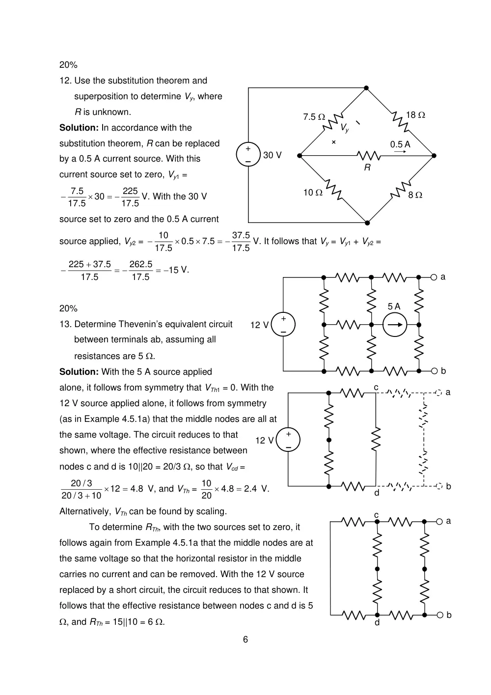
12. Use the substitution theorem and
superposition to determine Vy, where
R is unknown.
Solution: In accordance with the
substitution theorem, R can be replaced
by a 0.5 A current source. With this
current source set to zero, Vy1 =
17.5
225
30
17.5
7.5
= −
×
−
V. With the 30 V
source set to zero and the 0.5 A current
source applied, Vy2 =
17.5
37.5
7.5
0.5
17.5
10
= −
×
×
−
V. It follows that Vy = Vy1 + Vy2 =
15
17.5
262.5
17.5
37.5
225
= −
= −
+
−
V.
30 V
–
+
0.5 A
18 Ω
8 Ω
10 Ω
7.5 Ω
R
Vy
6
–
+
12 V
a
b
c
d
20%
13. Determine Thevenin’s equivalent circuit
between terminals ab, assuming all
resistances are 5 Ω.
Solution: With the 5 A source applied
alone, it follows from symmetry that VTh1 = 0. With the
12 V source applied alone, it follows from symmetry
(as in Example 4.5.1a) that the middle nodes are all at
the same voltage. The circuit reduces to that
shown, where the effective resistance between
nodes c and d is 10||20 = 20/3 Ω, so that Vcd =
4.8
12
10
20 / 3
20 / 3
=
×
+
V, and VTh =
2.4
4.8
20
10
=
×
V.
Alternatively, VTh can be found by scaling.
a
–
+
b
12 V
5 A
a
b
c
d
To determine RTh, with the two sources set to zero, it
follows again from Example 4.5.1a that the middle nodes are at
the same voltage so that the horizontal resistor in the middle
carries no current and can be removed. With the 12 V source
replaced by a short circuit, the circuit reduces to that shown. It
follows that the effective resistance between nodes c and d is 5
Ω, and RTh = 15||10 = 6 Ω.