
EECE 210 Exam 2 with Solution, Fall 2011
American University of Beirut · Electric Circuits · 9 pages · with solution

More EECE 210 files
- Exam 1 Fall 2018 Quiz 1 · Fall 2018ExamView
- Exam 2 Fall 2018 Quiz 2 · Fall 2018ExamView
- Exam 2 (Quiz 2) Clean Copy · Fall 2018ExamView
- Exam 1 · Spring 2016ExamView
- Exam PSpice Quiz · Fall 2016ExamView
- Exam 2 · Spring 2016ExamView
- Exam 2 · Spring 2016ExamView
- Exam 2 With Solution · Fall 2016Exam · with solutionView
Show the text of this exam
EECE 210 – Quiz 2
November 12, 2011
4%
1.
A circuit has 20 essential branches, 11 essential nodes and 10 meshes. How many
independent KCL equations can be written for this circuit?
A. 8
B. 6
C. 7
D. 10
E. 9
Answer: The number of independent KCL equations is one less than the number of
essential nodes.
Version 1: N = 11, number independent KCL equations = 10
Version 2: N = 10, number independent KCL equations = 9
Version 3: N = 9, number independent KCL equations = 8
Version 4: N = 8, number independent KCL equations = 7
Version 5: N = 7, number independent KCL equations = 6.
4%
2.
How many independent KVL equations can be written for the circuit of the preceding
question?
A. 11
B. 10
C. 9
D. 12
E. 13
Answer: The number of independent KVL equations is same as the number of meshes.
Version 1: L = 10, number independent KVL equations = 10
Version 2: L = 11, number independent KVL equations = 11
Version 3: L = 12, number independent KVL equations = 12
Version 4: L = 13, number independent KVL equations = 13
Version 5: L = 14, number independent KVL equations = 14.
1
4%
3.
Determine VO.
A. 2 V
B. 4 V
C. 0
D. 1.5 V
E. 2.5 V
Solution: Since the circuit does not have any
independent sources, VO = 0. This can also be
shown by analyzing the circuit. Thus, 1.25Vx =
VO, so I1 = Vx/1 = VO/1.25 = 0.8VO; I2 = 0.5VO/2 =
0.25VO; IO = VO/5 = 0.2VO. Applying KCL, 0.8VO +
0.25VO + 0.2VO = 0, or 1.25VO = 0, so VO = 0.
4%
4.
Given that Va = 25 V and Vb = 12 V. Determine Va if
node b is grounded instead of c.
A. 13 V
B. 37 V
C. 14 V
D. 15 V
E. 16 V
Solution: When node b is grounded, Vb = 0. Hence, 12 V
is subtracted from all node voltages, and Va = 25 – 12 = 13 V. Alternatively, it can be argued
that the voltage drop from a to b is 13 V irrespective of which node is grounded.
Version 1: Vb = 12, Va = 13 V
Version 2: Vb = 11, Va = 14 V
Version 3: Vb = 10, Va = 15 V
Version 4: Vb = 9, Va = 16 V
Version 5: Vb = 8, Va = 17 V.
4%
5.
The power dissipated in R is 8 W if ISRC is
applied alone, with VSRC set to zero, and is 0.5
W if VSRC is applied alone, with ISRC set to zero.
Determine the power dissipated in R if both
sources are applied together, with polarities that will give the largest current in R.
2
–
+
–
+
–
+
VO
0.5VO
–
+
Vx
0.25Vx
5
2
1
–
+
–
+
–
+
VO
0.5VO
–
+
Vx
0.25Vx
5
2
1
I1
I2
IO
–
+
VSRC
2
R
ISRC
2
A. 8.5 W
B. 18 W
C. 24.5 W
D. 32 W
E. 12.5 W
Solution: When ISRC source is applied alone, with VSRC set to zero, the current in R is A.
When VSRC is applied alone, with ISRC set to zero, the current in R is . With both sources
applied together to to give the largest current in R, the total current in R is and the power
dissipated in R is .
Version 1: PV = 0.5 W, PT = 8 + 4 + 0.5 = 12.5 W
Version 2: PV = 2 W, PT = 8 + 8 + 2 = 18 W
Version 3: PV = 4.5 W, PT = 8 + 12 + 4.5 = 24.5 W
Version 4: PV = 8 W, PT = 8 + 16 + 8 = 32 W
Version 5: PV = 12.5 W, PT = 8 + 20 + 12.5 = 40.5 W.
4%
6.
Determine Thevenin’s equivalent circuit (TEC)
looking into terminals ab, assuming VSRC = 5 V and
ISRC = 2 A.
A. VTh = 12 V, RTh = 2
B. VTh = 15 V, RTh = 6
C. VTh = 12 V, RTh = 6
D. VTh = 15 V, RTh = 2
E. TEC does not exist
Solution: On open circuit, ISCR flows through the 6
resistor, so that VTh = 6ISRC. If a test source is applied with the voltage source replaced by
short circuit and the current source replaced by an open circuit, the resistance looking into
terminals ab is RTh = 6 .
Version 1: ISRC = 2 A, VTh = 6ISRC = 12 V; RTh = 6
Version 2: ISRC = 2.5 A, VTh = 6ISRC = 15 V; RTh = 6
Version 3: ISRC = 3 A, VTh = 6ISRC = 18 V; RTh = 6
Version 4: ISRC = 3.5 A, VTh = 6ISRC = 21 V; RTh = 6
Version 5: ISRC = 4 A, VTh = 6ISRC = 24 V; RTh = 6 .
4%
3
–
+
VSRC
3
6
a
b
ISRC
VSRC
–
+
ISRC
5
a
b
7.
Determine Norton’s equivalent circuit (NEC) looking into terminals ab, assuming VSRC = 5
V and ISRC = 2 A.
A. IN = 2 A, RN = 5
B. NEC does not exist
C. IN = 3 A, RN = 5
D. IN = 4 A, RN = 5
E. IN = 2 A, RN = 0
Solution: On open circuit, VTh = VSRC. If VSRC and ISRC are set to zero, the resistance looking
into terminals ab is that of a short circuit, so RTh = 0. If terminals ab are short-circuited, IN
. Hence, TEC is the ideal voltage source VSRC, and NEC does not exist.
4%
8.
Determine TEC looking into
terminals ab, assuming VSRC = 4 V.
A. VTh = 4 V, RTh = 75
B. VTh = 4 V, RTh = 300
C. VTh = 4 V, RTh = 100
D. VTh = 3 V, RTh = 300
E. VTh = 3 V, RTh = 75
Solution: The 1 k resistor and the dependent current source are redundant because they
are in parallel with an ideal voltage source. The circuit reduces to a voltage source
connected to a 100 -300 voltage divider with terminals ab across the 300 resistor. It
follows that VTh = VSRC300/400 = 3VSRC/4. If a test source is applied with VSRC replaced by a
short circuit, the resistance looking into terminals ab is RTh = 100||300 = 75 .
Alternatively, if Ix is the current flowing in the 100 resistor toward node a, with the output
open circuited, then V = VSRC – 100Ix and V = 300Ix. Eliminating Ix gives VTh = V = 3VSRC/4.
Version 1: VSRC = 4 V, VTh = 3VSRC/4 = 3 V, RTh = 75
Version 2: VSRC = 8 V, VTh = 3VSRC/4 = 6 V, RTh = 75
Version 3: VSRC = 12 V, VTh = 3VSRC/4 = 9 V, RTh = 75
Version 4: VSRC = 16 V, VTh = 3VSRC/4 = 12 V, RTh = 75
Version 5: VSRC = 20 V, VTh = 3VSRC/4 = 15 V, RTh = 75
4%
9.
Determine, according to the substitution theorem,
which of the following ideal circuit elements can
replace the dependent source without affecting the
4
–
+
2 V
Ix
2Ix
3 A
2
–
+
VSRC
0.5V
1k
a
b
100
300
–
+
V
currents and voltages in the rest of the circuit (Mark all correct answers if you believe
that more than one answer is correct).
A. Independent 4 V source
B. Dependent 4 V source
C. Dependent 2 A source
D. Independent 2 A source
E. 2 resistor
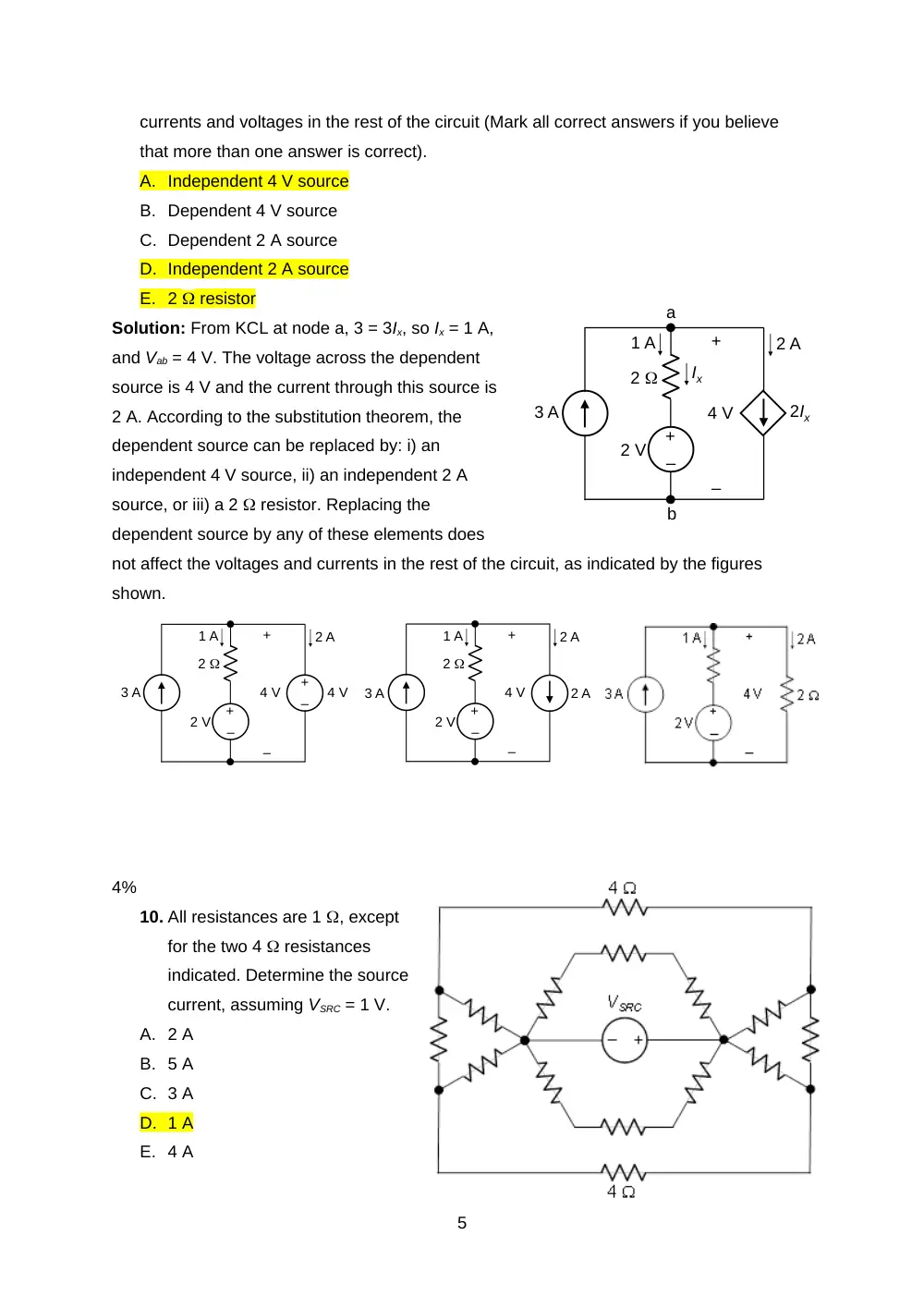
Solution: From KCL at node a, 3 = 3Ix, so Ix = 1 A,
and Vab = 4 V. The voltage across the dependent
source is 4 V and the current through this source is
2 A. According to the substitution theorem, the
dependent source can be replaced by: i) an
independent 4 V source, ii) an independent 2 A
source, or iii) a 2 resistor. Replacing the
dependent source by any of these elements does
not affect the voltages and currents in the rest of the circuit, as indicated by the figures
shown.
4%
10. All resistances are 1 , except
for the two 4 resistances
indicated. Determine the source
current, assuming VSRC = 1 V.
A. 2 A
B. 5 A
C. 3 A
D. 1 A
E. 4 A
5
–
+
2 V
Ix
2Ix
3 A
2
1 A
2 A
–
+
4 V
a
b
–
+
2 V
3 A
2
1 A
2 A
–
+
4 V
–
+
4 V
–
+
2 V
2 A
2
1 A
2 A
–
+
4 V
3 A
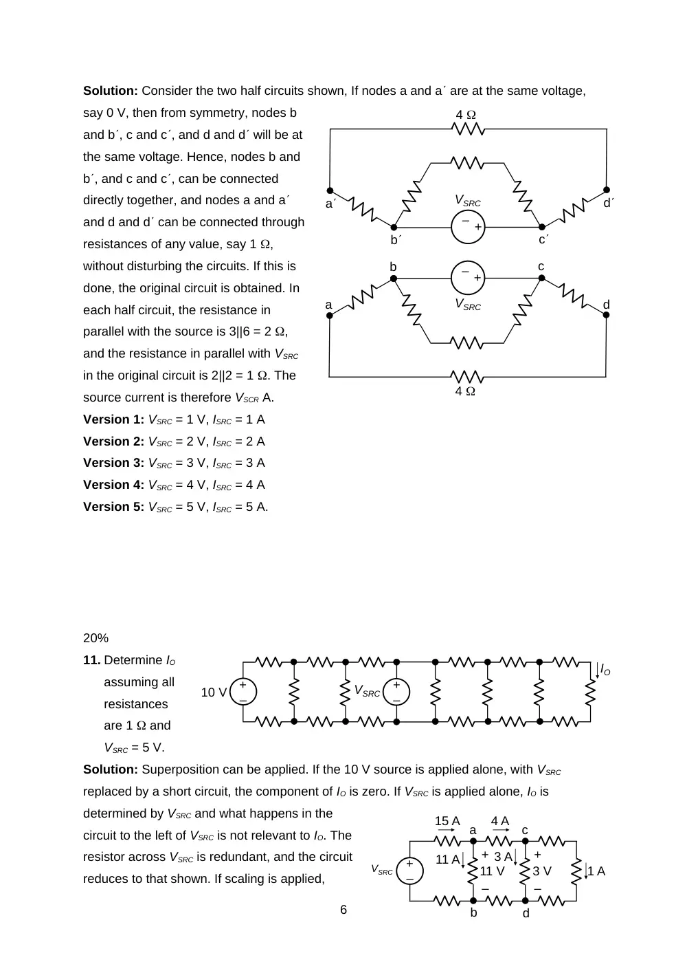
Solution: Consider the two half circuits shown, If nodes a and a are at the same voltage,
say 0 V, then from symmetry, nodes b
and b, c and c, and d and d will be at
the same voltage. Hence, nodes b and
b, and c and c, can be connected
directly together, and nodes a and a
and d and d can be connected through
resistances of any value, say 1 ,
without disturbing the circuits. If this is
done, the original circuit is obtained. In
each half circuit, the resistance in
parallel with the source is 3||6 = 2 ,
and the resistance in parallel with VSRC
in the original circuit is 2||2 = 1 . The
source current is therefore VSCR A.
Version 1: VSRC = 1 V, ISRC = 1 A
Version 2: VSRC = 2 V, ISRC = 2 A
Version 3: VSRC = 3 V, ISRC = 3 A
Version 4: VSRC = 4 V, ISRC = 4 A
Version 5: VSRC = 5 V, ISRC = 5 A.
20%
11. Determine IO
assuming all
resistances
are 1 and
VSRC = 5 V.
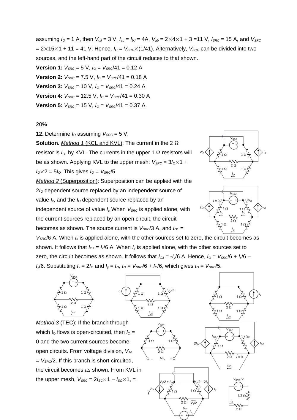
Solution: Superposition can be applied. If the 10 V source is applied alone, with VSRC
replaced by a short circuit, the component of IO is zero. If VSRC is applied alone, IO is
determined by VSRC and what happens in the
circuit to the left of VSRC is not relevant to IO. The
resistor across VSRC is redundant, and the circuit
reduces to that shown. If scaling is applied,
6
–
+
VSRC
1 A
–
+
3 A
3 V
4 A
–
+
11 V
11 A
15 A a
c
b
d
–
+
–
+
10 V
VSRC
IO
–
+
4
VSRC
4
–
+
VSRC
a
a
b
b
c
c
d
d
assuming IO = 1 A, then Vcd = 3 V, Iac = Ibd = 4A, Vab = 241 + 3 =11 V, ISRC = 15 A, and VSRC
= 2151 + 11 = 41 V. Hence, IO = VSRC(1/41). Alternatively, VSRC can be divided into two
sources, and the left-hand part of the circuit reduces to that shown.
Version 1: VSRC = 5 V, IO = VSRC/41 = 0.12 A
Version 2: VSRC = 7.5 V, IO = VSRC/41 = 0.18 A
Version 3: VSRC = 10 V, IO = VSRC/41 = 0.24 A
Version 4: VSRC = 12.5 V, IO = VSRC/41 = 0.30 A
Version 5: VSRC = 15 V, IO = VSRC/41 = 0.37 A.
20%
12. Determine IO assuming VSRC = 5 V.
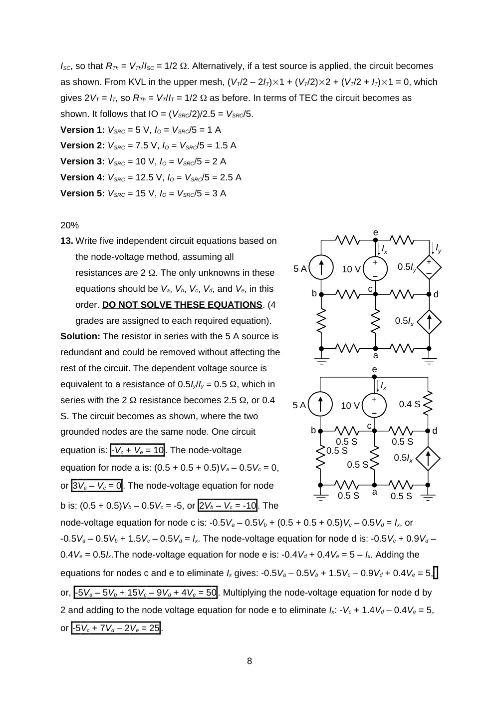
Solution. Method 1
(KCL and KVL)
: The current in the 2
resistor is IO, by KVL. The currents in the upper 1 resistors will
be as shown. Applying KVL to the upper mesh: VSRC = 3IO1 +
IO2 = 5IO. This gives IO = VSRC/5.
Method 2
(Superposition)
: Superposition can be applied with the
2IO dependent source replaced by an independent source of
value Ix, and the IO dependent source replaced by an
independent source of value Iy. When VSRC is applied alone, with
the current sources replaced by an open circuit, the circuit
becomes as shown. The source current is VSRC/3 A, and IO1 =
VSRC/6 A. When Ix is applied alone, with the other sources set to zero, the circuit becomes as
shown. It follows that IO2 = Ix/6 A. When Iy is applied alone, with the other sources set to
zero, the circuit becomes as shown. It follows that IO3 = -Iy/6 A. Hence, IO = VSRC/6 + Ix/6 –
Iy/6. Substituting Ix = 2IO and Iy = IO, IO = VSRC/6 + IO/6, which gives IO = VSRC/5.
Method 3
(TEC)
: If the branch through
which IO flows is open-circuited, then IO =
0 and the two current sources become
open circuits. From voltage division, VTh
= VSRC/2. If this branch is short-circuited,
the circuit becomes as shown. From KVL in
the upper mesh, VSRC = 2ISC1 – ISC1, =
7
–
+
IO
2
1
1
1
1
IO
2IO
VSRC
–
+
IO1
2
1
1
1
1
VSRC
IO2
2
1
1
1
1
Ix
Ix/3
ISC, so that RTh = VTh/ISC = 1/2 . Alternatively, if a test source is applied, the circuit becomes
as shown. From KVL in the upper mesh, (VT/2 – 2IT)1 + (VT/2)2 + (VT/2 + IT)1 = 0, which
gives 2VT = IT, so RTh = VT/IT = 1/2 as before. In terms of TEC the circuit becomes as
shown. It follows that IO = (VSRC/2)/2.5 = VSRC/5.
Version 1: VSRC = 5 V, IO = VSRC/5 = 1 A
Version 2: VSRC = 7.5 V, IO = VSRC/5 = 1.5 A
Version 3: VSRC = 10 V, IO = VSRC/5 = 2 A
Version 4: VSRC = 12.5 V, IO = VSRC/5 = 2.5 A
Version 5: VSRC = 15 V, IO = VSRC/5 = 3 A
20%
13. Write five independent circuit equations based on
the node-voltage method, assuming all
resistances are 2 . The only unknowns in these
equations should be Va, Vb, Vc, Vd, and Ve, in this
order. DO NOT SOLVE THESE EQUATIONS. (4
grades are assigned to each required equation).
Solution: The resistor in series with the 5 A source is
redundant and could be removed without affecting the
rest of the circuit. The dependent voltage source is
equivalent to a resistance of 0.5Iy/Iy = 0.5 , which in
series with the 2 resistance becomes 2.5 , or 0.4
S. The circuit becomes as shown, where the two
grounded nodes are the same node. One circuit
equation is: -Vc + Ve = 10. The node-voltage
equation for node a is: (0.5 + 0.5 + 0.5)Va – 0.5Vc = 0,
or 3Va – Vc = 0. The node-voltage equation for node
b is: (0.5 + 0.5)Vb – 0.5Vc = -5, or 2Vb – Vc = -10. The
node-voltage equation for node c is: -0.5Va – 0.5Vb + (0.5 + 0.5 + 0.5)Vc – 0.5Vd = Ix, or
-0.5Va – 0.5Vb + 1.5Vc – 0.5Vd = Ix. The node-voltage equation for node d is: -0.5Vc + 0.9Vd –
0.4Ve = 0.5Ix.The node-voltage equation for node e is: -0.4Vd + 0.4Ve = 5 – Ix. Adding the
equations for nodes c and e to eliminate Ix gives: -0.5Va – 0.5Vb + 1.5Vc – 0.9Vd + 0.4Ve = 5,
or, -5Va – 5Vb + 15Vc – 9Vd + 4Ve = 50. Multiplying the node-voltage equation for node d by
2 and adding to the node voltage equation for node e to eliminate Ix: -Vc + 1.4Vd – 0.4Ve = 5,
or -5Vc + 7Vd – 2Ve = 25.
8
–
+
b
c
0.5Ix
–
+
0.5Iy
a
d
e
Ix
Iy
10 V
5 A
–
+
b
c
0.5Ix
a
d
e
Ix
10 V
5 A
0.4 S
0.5 S
0.5 S
0.5 S
0.5 S
0.5 S
0.5 S
9