
EECE 210 Exam 3 with Solution, Fall 2011
American University of Beirut · Electric Circuits · 7 pages · with solution

More EECE 210 files
- Exam 1 Fall 2018 Quiz 1 · Fall 2018ExamView
- Exam 2 Fall 2018 Quiz 2 · Fall 2018ExamView
- Exam 2 (Quiz 2) Clean Copy · Fall 2018ExamView
- Exam 1 · Spring 2016ExamView
- Exam PSpice Quiz · Fall 2016ExamView
- Exam 2 · Spring 2016ExamView
- Exam 2 · Spring 2016ExamView
- Exam 2 With Solution · Fall 2016Exam · with solutionView
Show the text of this exam
EECE 210 – Quiz 3
December 10, 2011
4%
1.
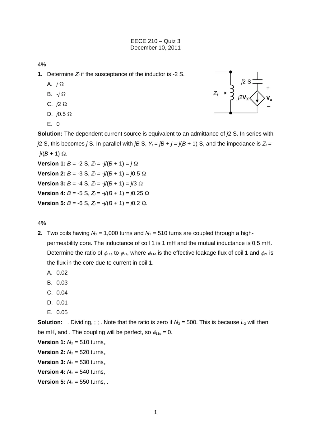
Determine Zi if the susceptance of the inductor is -2 S.
A. j
B. -j
C. j2
D. j0.5
E. 0
Solution: The dependent current source is equivalent to an admittance of j2 S. In series with
j2 S, this becomes j S. In parallel with jB S, Yi = jB + j = j(B + 1) S, and the impedance is Zi =
-j/(B + 1) .
Version 1: B = -2 S, Zi = -j/(B + 1) = j
Version 2: B = -3 S, Zi = -j/(B + 1) = j0.5
Version 3: B = -4 S, Zi = -j/(B + 1) = j/3
Version 4: B = -5 S, Zi = -j/(B + 1) = j0.25
Version 5: B = -6 S, Zi = -j/(B + 1) = j0.2 .
4%
2.
Two coils having N1 = 1,000 turns and N2 = 510 turns are coupled through a high-
permeability core. The inductance of coil 1 is 1 mH and the mutual inductance is 0.5 mH.
Determine the ratio of 11e to 21, where 11e is the effective leakage flux of coil 1 and 21 is
the flux in the core due to current in coil 1.
A. 0.02
B. 0.03
C. 0.04
D. 0.01
E. 0.05
Solution: , . Dividing, ; ; . Note that the ratio is zero if N2 = 500. This is because L2 will then
be mH, and . The coupling will be perfect, so 11e = 0.
Version 1: N2 = 510 turns,
Version 2: N2 = 520 turns,
Version 3: N2 = 530 turns,
Version 4: N2 = 540 turns,
Version 5: N2 = 550 turns, .
1
j2VX
–
+
Vx
j2 S
Zi
4%
3.
Two identical, magnetically coupled coils are connected in series. When the same
current is passed though both coils, but with the connections of one coil reversed, the
magnetic stored energy is multiplied by a factor of 2. Determine the coefficient of
coupling of the coils.
A. 0.33
B. 0.5
C. 0.6
D. 0.67
E. 0.75
Solution: The stored energy is The ratio of the two stored energies is , or, , so
Version 1: = 2,
Version 2: = 3,
Version 3: = 4,
Version 4: = 5,
Version 5: = 7, .
4%
4.
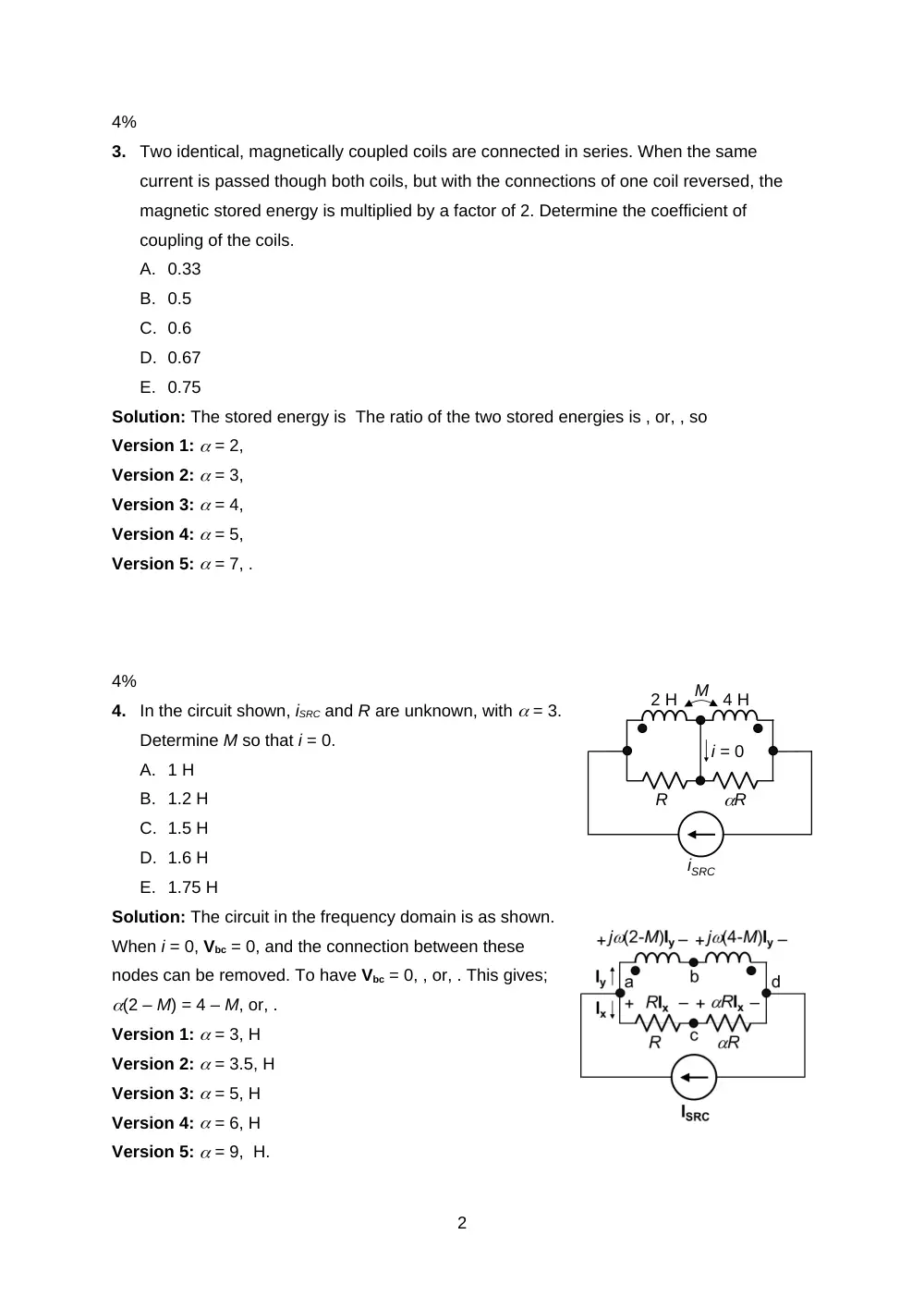
In the circuit shown, iSRC and R are unknown, with = 3.
Determine M so that i = 0.
A. 1 H
B. 1.2 H
C. 1.5 H
D. 1.6 H
E. 1.75 H
Solution: The circuit in the frequency domain is as shown.
When i = 0, Vbc = 0, and the connection between these
nodes can be removed. To have Vbc = 0, , or, . This gives;
(2 – M) = 4 – M, or, .
Version 1: = 3, H
Version 2: = 3.5, H
Version 3: = 5, H
Version 4: = 6, H
Version 5: = 9, H.
2
iSRC
R
R
M
2 H
4 H
i = 0
4%
5.
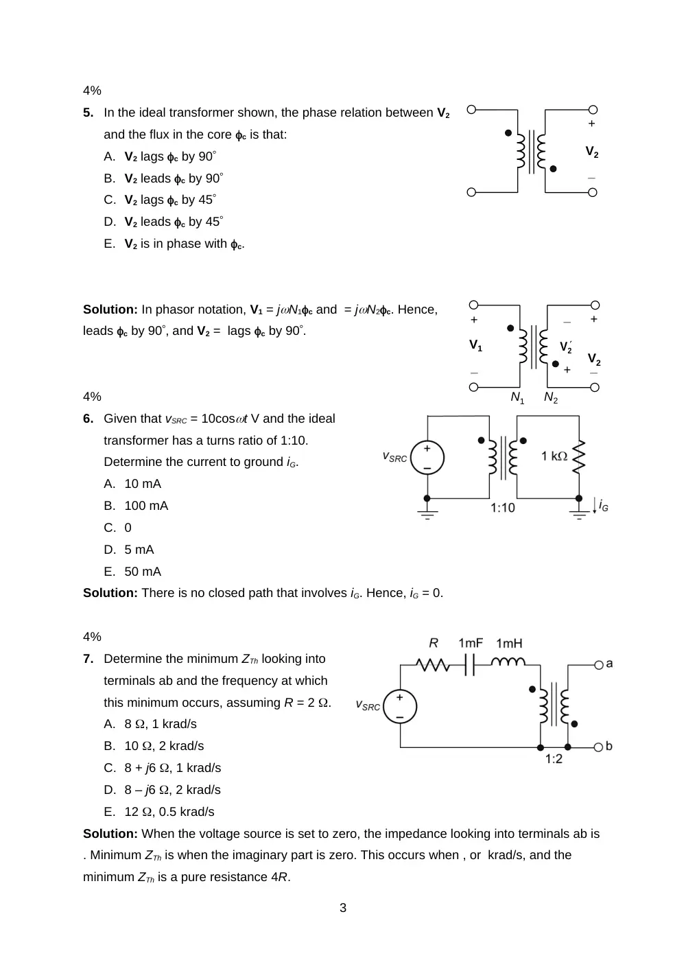
In the ideal transformer shown, the phase relation between V2
and the flux in the core c is that:
A. V2 lags c by 90
B. V2 leads c by 90
C. V2 lags c by 45
D. V2 leads c by 45
E. V2 is in phase with c.
Solution: In phasor notation, V1 = jN1c and = jN2c. Hence,
leads c by 90, and V2 = lags c by 90.
4%
6.
Given that vSRC = 10cost V and the ideal
transformer has a turns ratio of 1:10.
Determine the current to ground iG.
A. 10 mA
B. 100 mA
C. 0
D. 5 mA
E. 50 mA
Solution: There is no closed path that involves iG. Hence, iG = 0.
4%
7.
Determine the minimum ZTh looking into
terminals ab and the frequency at which
this minimum occurs, assuming R = 2 .
A. 8 , 1 krad/s
B. 10 , 2 krad/s
C. 8 + j6 , 1 krad/s
D. 8 – j6 , 2 krad/s
E. 12 , 0.5 krad/s
Solution: When the voltage source is set to zero, the impedance looking into terminals ab is
. Minimum ZTh is when the imaginary part is zero. This occurs when , or krad/s, and the
minimum ZTh is a pure resistance 4R.
3
+
_
V2
2
V
+
_
V1
+
_
V2
+
_
N1
N2
Version 1: R = 2 , ZTh = 4R = 8
Version 2: R = 2.5 , ZTh = 4R = 10
Version 3: R = 3 , ZTh = 4R = 12
Version 4: R = 3.5 , ZTh = 4R = 14
Version 5: R = 4 , ZTh = 4R = 16 .
4%
8.
Determine VTh = Vab in the preceding problem at a frequency that is twice the frequency
for minimum ZTh, assuming vSRC = 2cos(t – 30) V.
A. 4cos(t + 150) V
B. 4cos(t – 30) V
C. 8cos(t + 150) V
D. 8cos(t – 30) V
E. 16cos(t – 30) V
Solution: Since the secondary is open circuited, the primary current is zero at all
frequencies. The primary voltage is vSRC and Vab = -2vSRC = -2Vmcos(t – 30) = 2Vmcos(t +
150) V.
Version 1: Vm = 2 V, Vab = 2Vmcos(t + 150) = 4cos(t + 150) V
Version 2: Vm = 2.5 V, Vab = 2Vmcos(t + 150) = 5cos(t + 150) V
Version 3: Vm = 3 V, Vab = 2Vmcos(t + 150) = 6cos(t + 150) V
Version 4: Vm = 3.5 V, Vab = 2Vmcos(t + 150) = 7cos(t + 150) V
Version 5: Vm = 4 V, Vab = 2Vmcos(t + 150) = 8cos(t + 150) V.
4%
9.
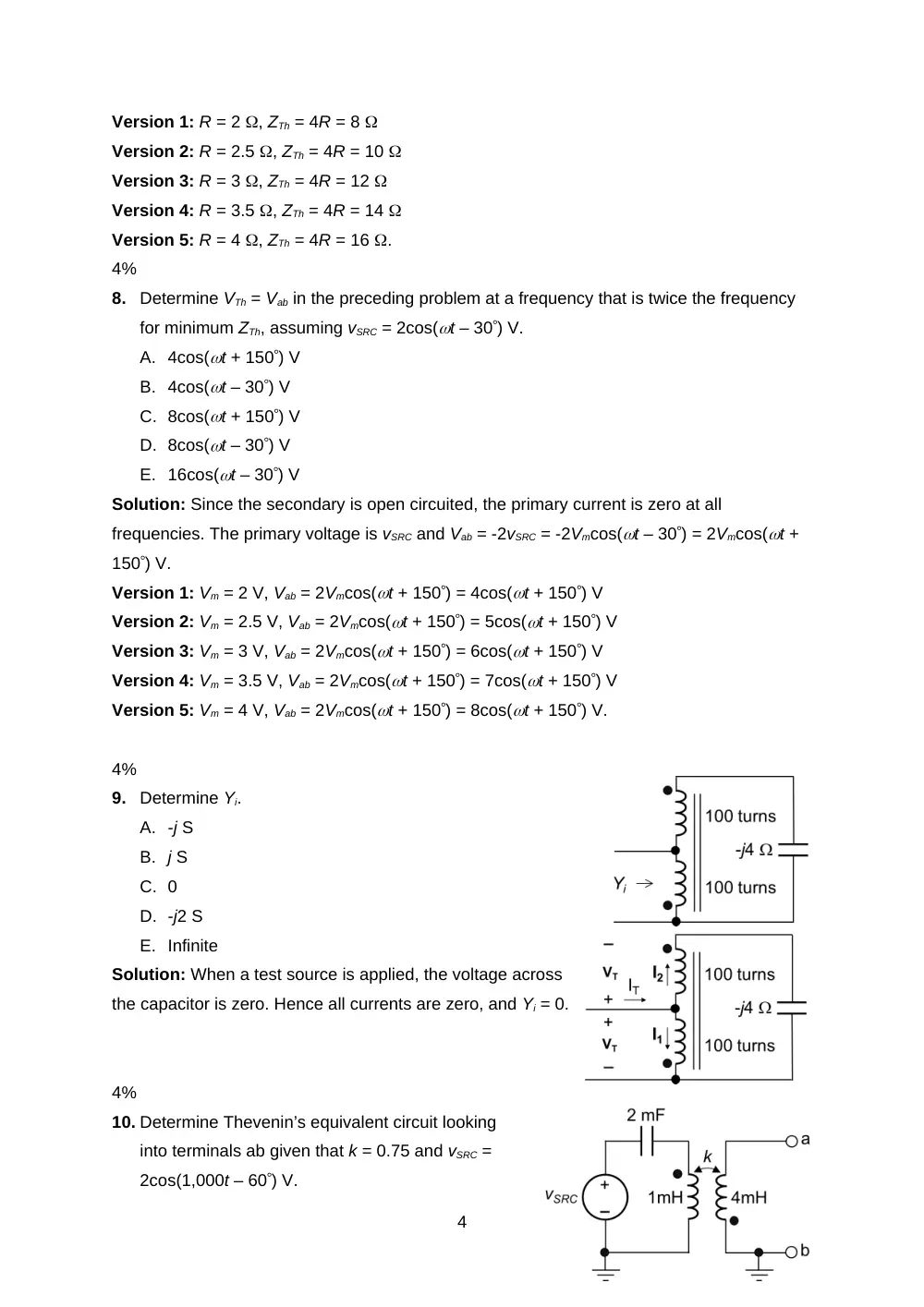
Determine Yi.
A. -j S
B. j S
C. 0
D. -j2 S
E. Infinite
Solution: When a test source is applied, the voltage across
the capacitor is zero. Hence all currents are zero, and Yi = 0.
4%
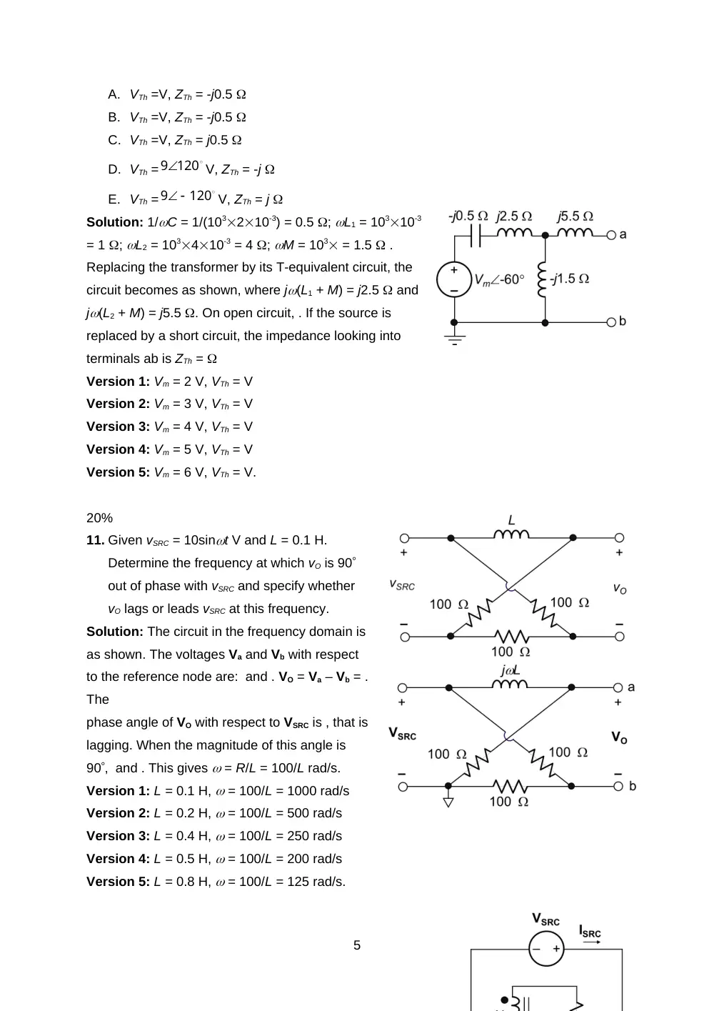
10. Determine Thevenin’s equivalent circuit looking
into terminals ab given that k = 0.75 and vSRC =
2cos(1,000t – 60) V.
4
A. VTh =V, ZTh = -j0.5
B. VTh =V, ZTh = -j0.5
C. VTh =V, ZTh = j0.5
D. VTh =
V, ZTh = -j
E. VTh =
V, ZTh = j
Solution: 1/C = 1/(103210-3) = 0.5 ; L1 = 10310-3
= 1 ; L2 = 103410-3 = 4 ; M = 103 = 1.5 .
Replacing the transformer by its T-equivalent circuit, the
circuit becomes as shown, where j(L1 + M) = j2.5 and
j(L2 + M) = j5.5 . On open circuit, . If the source is
replaced by a short circuit, the impedance looking into
terminals ab is ZTh =
Version 1: Vm = 2 V, VTh = V
Version 2: Vm = 3 V, VTh = V
Version 3: Vm = 4 V, VTh = V
Version 4: Vm = 5 V, VTh = V
Version 5: Vm = 6 V, VTh = V.
20%
11. Given vSRC = 10sint V and L = 0.1 H.
Determine the frequency at which vO is 90
out of phase with vSRC and specify whether
vO lags or leads vSRC at this frequency.
Solution: The circuit in the frequency domain is
as shown. The voltages Va and Vb with respect
to the reference node are: and . VO = Va – Vb = .
The
phase angle of VO with respect to VSRC is , that is
lagging. When the magnitude of this angle is
90, and . This gives = R/L = 100/L rad/s.
Version 1: L = 0.1 H, = 100/L = 1000 rad/s
Version 2: L = 0.2 H, = 100/L = 500 rad/s
Version 3: L = 0.4 H, = 100/L = 250 rad/s
Version 4: L = 0.5 H, = 100/L = 200 rad/s
Version 5: L = 0.8 H, = 100/L = 125 rad/s.
5
120
9
120
9
20%
12. Determine ISRC, in polar coordinates, assuming N2/N1 = 2 and VSRC = 1 V.
Solution: The voltages and currents of the ideal autotransformer may be assigned as
shown. From KVL in the mesh involving R, C, and the transformer: 2I2 + 2V1 + V1 – (-j2I2) =
0, or, 3V1 = -2(1 + j)I2. From KVL in the upper mesh, 2I2 + 2V1 = VSRC. Substituting for V1: 2I2
– (4/3)(1 + j)I2 = (2/3)(1 – j2)I2 = VSRC, or, . Since ISRC = 3I2, = 0.9(1 + j2)VSRC A.
Version 1: VSRC = 1 V, ISRC = 0.9(1 + j2) A = 2.0163.4 A
Version 2: VSRC = 2 V, ISR = 1.8(1 + j2) A = 4.0263.4 A
Version 3: VSRC = 3 V, ISRC = 2.7(1 + j2) A = 6.0363.4 A
Version 4: VSRC = 4 V, ISRC = 3.6(1 + j2) A = 8.0563.4 A
Version 5: VSRC = 5 V, ISRC = 4.5(1 + j2) A = 10.163.4 A
20%
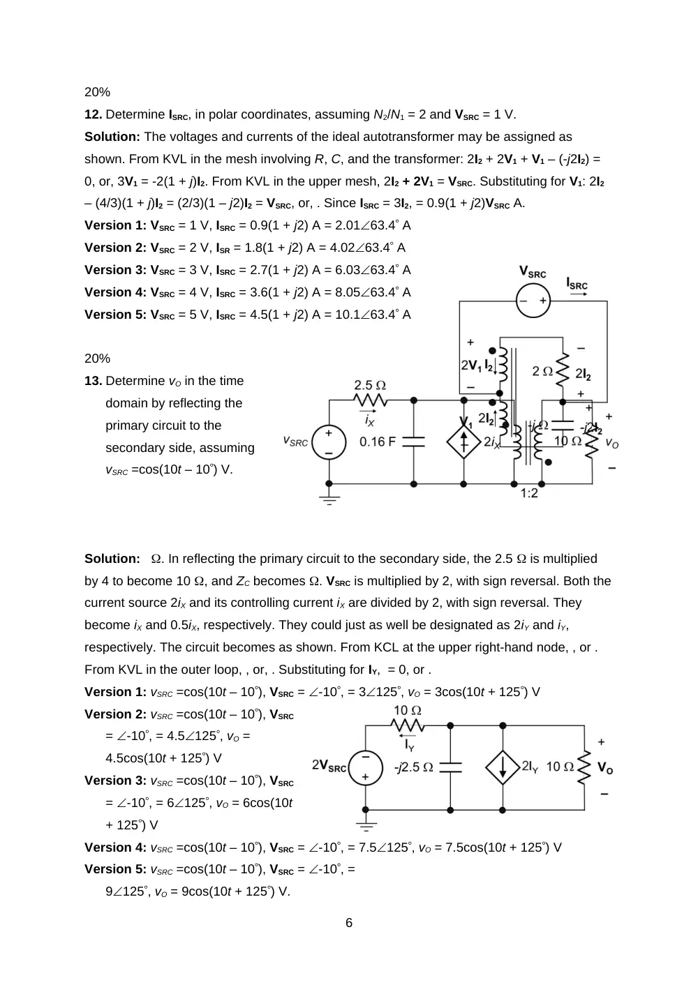
13. Determine vO in the time
domain by reflecting the
primary circuit to the
secondary side, assuming
vSRC =cos(10t – 10) V.
Solution: . In reflecting the primary circuit to the secondary side, the 2.5 is multiplied
by 4 to become 10 , and ZC becomes . VSRC is multiplied by 2, with sign reversal. Both the
current source 2iX and its controlling current iX are divided by 2, with sign reversal. They
become iX and 0.5iX, respectively. They could just as well be designated as 2iY and iY,
respectively. The circuit becomes as shown. From KCL at the upper right-hand node, , or .
From KVL in the outer loop, , or, . Substituting for IY, = 0, or .
Version 1: vSRC =cos(10t – 10), VSRC = -10, = 3125, vO = 3cos(10t + 125) V
Version 2: vSRC =cos(10t – 10), VSRC
= -10, = 4.5125, vO =
4.5cos(10t + 125) V
Version 3: vSRC =cos(10t – 10), VSRC
= -10, = 6125, vO = 6cos(10t
+ 125) V
Version 4: vSRC =cos(10t – 10), VSRC = -10, = 7.5125, vO = 7.5cos(10t + 125) V
Version 5: vSRC =cos(10t – 10), VSRC = -10, =
9125, vO = 9cos(10t + 125) V.
6
7