
EECE 210 Exam 3 with Solution, Fall 2014
American University of Beirut · Electric Circuits · 7 pages · with solution



More EECE 210 files
- Exam 1 Fall 2018 Quiz 1 · Fall 2018ExamView
- Exam 2 Fall 2018 Quiz 2 · Fall 2018ExamView
- Exam 2 (Quiz 2) Clean Copy · Fall 2018ExamView
- Exam 1 · Spring 2016ExamView
- Exam PSpice Quiz · Fall 2016ExamView
- Exam 2 · Spring 2016ExamView
- Exam 2 · Spring 2016ExamView
- Exam 2 With Solution · Fall 2016Exam · with solutionView
Show the text of this exam
EECE 210
Quiz 3, November 21, 2014
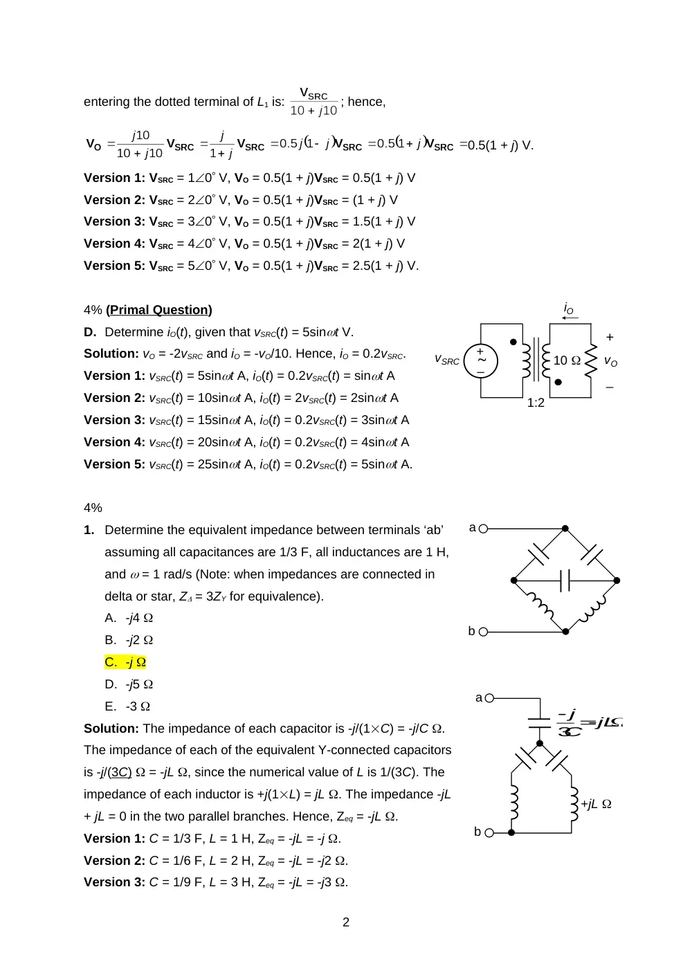
4% (Primal Question)
A. Determine vO(t), assuming vSRC(t) = cos10t V.
Solution: jL = j ,
;
V.
Version 1: vSRC(t) = cos10t V;
V
Version 2: vSRC(t) = 2cos10t V;
V
Version 3: vSRC(t) = 3cos10t V;
V
Version 4: vSRC(t) = 4cos10t V;
V
Version 5: vSRC(t) = 5cos10t V;
V.
4% (Primal Question)
B. Given v1(t) = 12sin(t + 60) V and v2(t) = -6cos(t + 30) V. Express v1(t) as a cosine
function, convert v1(t) and v2(t) to phasors, and draw them on a phasor diagram.
Solution: cos(t – 90) = sint; hence, v1(t) = 12cos(t – 30) V; V1 =
12-30 V, V2 = -630 = 6210 V.
Version 1: v1(t) = 12cos(t – 30) V and v2(t) = 6cos(t + 210) V
Version 2: v1(t) = 6cos(t – 30) V and v2(t) = 6cos(t + 210) V
Version 3: v1(t) = 6cos(t – 30) V and v2(t) = 12cos(t + 210) V
Version 4: v1(t) = 12cos(t – 60) V and v2(t) = 6cos(t + 240) V
Version 5: v1(t) = 6cos(t – 60) V and v2(t) = 12cos(t + 240) V.
4% (Primal Question)
C. Determine VO, given VSRC = 10 V, L1 = 10 ,
L2 = 40 , and k = 0.5. Express VO in
rectangular coordinates (of the form a + jb).
Solution: M = 0.5
. The current
1
–
+
L1
L2
k
10
VSRC0
VO
+
_
–
+
0.1 H
1
vO
+
_
vSRC
Re
Im
V1
V2
entering the dotted terminal of L1 is:
; hence,
0.5(1 + j) V.
Version 1: VSRC = 10 V, VO = 0.5(1 + j)VSRC = 0.5(1 + j) V
Version 2: VSRC = 20 V, VO = 0.5(1 + j)VSRC = (1 + j) V
Version 3: VSRC = 30 V, VO = 0.5(1 + j)VSRC = 1.5(1 + j) V
Version 4: VSRC = 40 V, VO = 0.5(1 + j)VSRC = 2(1 + j) V
Version 5: VSRC = 50 V, VO = 0.5(1 + j)VSRC = 2.5(1 + j) V.
4% (Primal Question)
D. Determine iO(t), given that vSRC(t) = 5sint V.
Solution: vO = -2vSRC and iO = -vO/10. Hence, iO = 0.2vSRC.
Version 1: vSRC(t) = 5sint A, iO(t) = 0.2vSRC(t) = sint A
Version 2: vSRC(t) = 10sint A, iO(t) = 2vSRC(t) = 2sint A
Version 3: vSRC(t) = 15sint A, iO(t) = 0.2vSRC(t) = 3sint A
Version 4: vSRC(t) = 20sint A, iO(t) = 0.2vSRC(t) = 4sint A
Version 5: vSRC(t) = 25sint A, iO(t) = 0.2vSRC(t) = 5sint A.
4%
1.
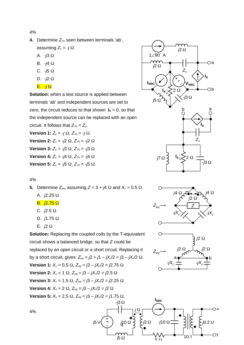
Determine the equivalent impedance between terminals ‘ab’
assuming all capacitances are 1/3 F, all inductances are 1 H,
and = 1 rad/s (Note: when impedances are connected in
delta or star, Z = 3ZY for equivalence).
A. -j4
B. -j2
C. -j
D. -j5
E. -3
Solution: The impedance of each capacitor is -j/(1C) = -j/C .
The impedance of each of the equivalent Y-connected capacitors
is -j/(3 C ) = -jL , since the numerical value of L is 1/(3C). The
impedance of each inductor is +j(1L) = jL . The impedance -jL
+ jL = 0 in the two parallel branches. Hence, Zeq = -jL .
Version 1: C = 1/3 F, L = 1 H, Zeq = -jL = -j .
Version 2: C = 1/6 F, L = 2 H, Zeq = -jL = -j2 .
Version 3: C = 1/9 F, L = 3 H, Zeq = -jL = -j3 .
2
a
b
b
a
3
jL
C
j
+jL
vO
+
_
1:2
10
vSRC
iO
–
+
–
+
vSRC
+ vO
_
1 H
1 H
R
R
Version 4: C = 1/12 F, L = 4 H, Zeq = -jL = -j4 .
Version 5: C = 1/15 F, L = 5 H, Zeq = -jL = -j5 . .
4%
2.
If the power dissipated in the 5 resistor is 1 W,
determine the power dissipated in the dual of the
5 resistor in the circuit that is the dual of the
given circuit.
A. 1 W
B. 4 W
C. 3 W
D. 2 W
E. 5 W
Solution: By definition of duality, voltage and current are interchanged in each element in a
given circuit and its dual in the dual circuit. The power therefore remains the same.
Version 1: P = 1 W
Version 2: P = 2 W
Version 3: P = 3 W
Version 4: P = 4 W
Version 5: P = 5 W.
4%
3.
Determine , assuming vSRC = 2cost and vO = 2sint and R = 2 .
A. 4 rad/s
B. 5 rad/s
C. 6 rad/s
D. 2 rad/s
E. 3 rad/s
Solution:
; -90 = -2tan-1(L/R);
tan(L/R) = 1; = R/L = R.
Version 1: R = 2 , = 2 rad/s
Version 2: R = 3 , = 3 rad/s
Version 3: R = 4 , = 4 rad/s
Version 4: R = 5 , = 5 rad/s
Version 5: R = 6 , = 6 rad/s.
3
+
–
VSRC
1 H
5
2 F
10
–
+
j5
-j3
j5 V
j10
j
j2
10:1
-j10
5
ISRC
a
b
j0.2
4%
4.
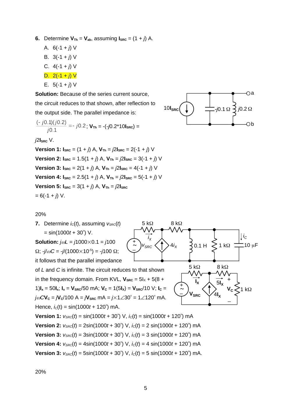
Determine ZTh seen between terminals ‘ab’,
assuming Zc = -j .
A. -j3
B. -j4
C. -j5
D. -j2
E. -j
Solution: when a test source is applied between
terminals ‘ab’ and independent sources are set to
zero, the circuit reduces to that shown. IX = 0, so that
the independent source can be replaced with an open
circuit. It follows that ZTh = Zc.
Version 1: Zc = -j , ZTh = -j
Version 2: Zc = -j2 , ZTh = -j2
Version 3: Zc = -j3 , ZTh = -j3
Version 4: Zc = -j4 , ZTh = -j4
Version 5: Zc = -j5 , ZTh = -j5 .
4%
5.
Determine Zeq, assuming Z = 3 + j4 and Xc = 0.5 .
A. j2.25
B. j2.75
C. j2.5
D. j1.75
E. j2
Solution: Replacing the coupled coils by the T-equivalent
circuit shows a balanced bridge, so that Z could be
replaced by an open circuit or a short circuit. Replacing it
by a short circuit, gives: Zeq = j2 + j1 – jXc/2 = j3 – jXc/2 .
Version 1: Xc = 0.5 , Zeq = j3 – jXc/2 = j2.75
Version 2: Xc = 1 , Zeq = j3 – jXc/2 = j2.5
Version 3: Xc = 1.5 , Zeq = j3 – jXc/2 = j2.25
Version 4: Xc = 2 , Zeq = j3 – jXc/2 = j2
Version 5: Xc = 2.5 , Zeq = j3 – jXc/2 = j1.75 .
4%
4
j2
j4
j4
Z
-jXc
-jXc
Zeq
Zeq
a
b
j2
j2
j2
-jXc
-jXc
-j3
2
IX
VSRC
ISRC
j5
IX
j2
Zc
j2
190 A
a
b
-j3
2
IX
j7
IX
Zc
a
b
6.
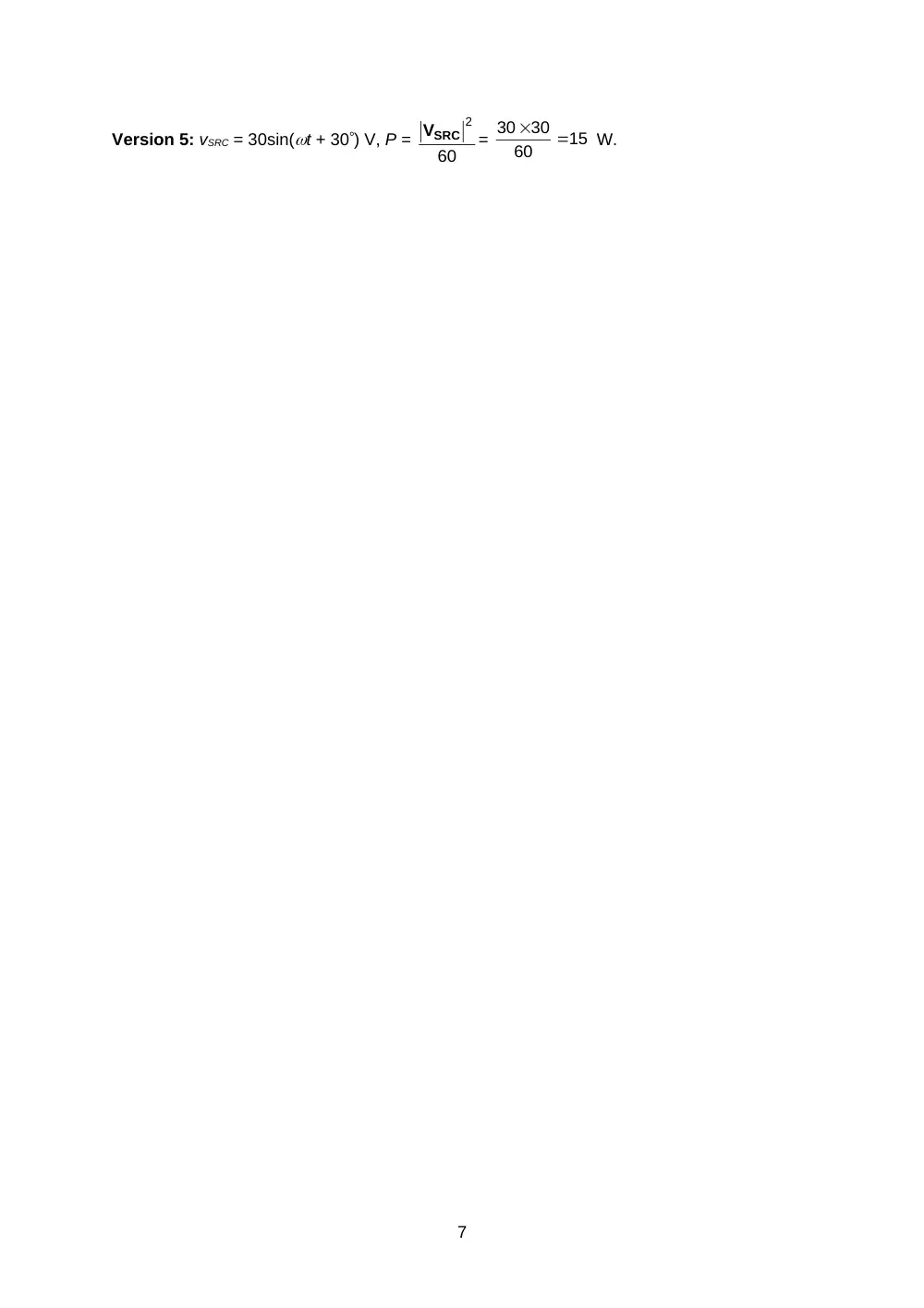
Determine VTh = Vab, assuming ISRC = (1 + j) A.
A. 6(-1 + j) V
B. 3(-1 + j) V
C. 4(-1 + j) V
D. 2(-1 + j) V
E. 5(-1 + j) V
Solution: Because of the series current source,
the circuit reduces to that shown, after reflection to
the output side. The parallel impedance is:
; VTh = -(-j0.2*10ISRC) =
j2ISRC V.
Version 1: ISRC = (1 + j) A, VTh = j2ISRC = 2(-1 + j) V
Version 2: ISRC = 1.5(1 + j) A, VTh = j2ISRC = 3(-1 + j) V
Version 3: ISRC = 2(1 + j) A, VTh = j2ISRC = 4(-1 + j) V
Version 4: ISRC = 2.5(1 + j) A, VTh = j2ISRC = 5(-1 + j) V
Version 5: ISRC = 3(1 + j) A, VTh = j2ISRC
= 6(-1 + j) V.
20%
7.
Determine iC(t), assuming vSRC(t)
= sin(1000t + 30) V.
Solution: jL = j10000.1 = j100
; -j/C = -j/(100010-5) = -j100 ;
it follows that the parallel impedance
of L and C is infinite. The circuit reduces to that shown
in the frequency domain. From KVL, VSRC = 5IX + 5(8 +
1)Ix = 50Ix; Ix = VSRC/50 mA; VC = 1(5IX) = VSRC/10 V; IC =
jCVC = jVC/100 A = jVSRC mA = j130 = 1120 mA.
Hence, iC(t) = sin(1000t + 120) mA.
Version 1: vSRC(t) = sin(1000t + 30) V, iC(t) = sin(1000t + 120) mA
Version 2: vSRC(t) = 2sin(1000t + 30) V, iC(t) = 2 sin(1000t + 120) mA
Version 3: vSRC(t) = 3sin(1000t + 30) V, iC(t) = 3 sin(1000t + 120) mA
Version 4: vSRC(t) = 4sin(1000t + 30) V, iC(t) = 4 sin(1000t + 120) mA
Version 3: vSRC(t) = 5sin(1000t + 30) V, iC(t) = 5 sin(1000t + 120) mA.
20%
5
a
b
j0.2
-j0.1
10ISRC
1 k
10 F
0.1 H
–
+
8 k
5 k
4iX
vSRC
iC
iX
1 k
–
+
8 k
5 k
4IX
VSRC
IX
VC
+
_
5IX
V1
+
_
–
+
1:2
Io
0.5Io
10
30
VSRC
0.5Io
Io
2V1
+
_
1.5Io
8.
(a) Derive the mesh-current equations
(15 grades); (b) determine Vab (5
grades).
Solution: Mesh 1: j20I1 + j10I2 – j10I4 = VY,
where VY is a voltage rise across the
dependent source in the direction of I1. Mesh
2: j10I1 + (j10 – j10)I2 + – (-j10I3) =
-VY. Adding these: j30I1 + j10I2 + j10I3 – j10I4
= 0; Substituting I4 = -j and I3 = 1 and
dividing by j10: 3I1 + I2 = -1 – j. Also, VX = I2
– I1, where Vx = 3(1 + j). Substituting for I2:
-4I1 = (1 + j) + 3(1 + j) = 4(1 + j), or -I1 = (1 + j).
Vab = j10(I4 – I1) = j10( -j + 1 + j) = j10 V.
20%
9.
Determine the power dissipated in the 30 resistor
given that vSRC = 6sin(t + 30) V.
Solution: The circuit is represented in the frequency
domain as shown, with the voltages and currents
assigned as indicated. From Ohm’s law on the secondary
side, 2V1 = 30Io, or V1 = 15Io. From KVL on the primary
side, VSRC = 15Io + V1. Substituting for V1, VSRC = 30Io,
or Io = VSRC/30. Power dissipated in 30 resistor is P =
W.
Version 1: vSRC = 6sin(t + 30) V, P =
60
2
VSRC
=
36/60 = 0.6 W
Version 2: vSRC = 12sin(t + 30) V, P =
60
2
VSRC
=
2.4
60
12
12
W.
Version 3: vSRC = 18sin(t + 30) V, P =
60
2
VSRC
=
5.4
60
18
18
W.
Version 4: vSRC = 24sin(t + 30) V, P =
60
2
VSRC
=
9.6
60
24
24
W.
6
–
+
1:2
iO
0.5iO
10
30
vSRC
VX
j A
b
3
1 A
j10
j10
j10
+
_
VX
a
I4
I1
I2
I3
j10
-j10
Version 5: vSRC = 30sin(t + 30) V, P =
60
2
VSRC
=
15
60
30
30
W.
7