
EECE 210 Problems, Fall 2010
American University of Beirut · Electric Circuits · 30 pages


Showing the first 10 of 30 pages. Download the PDF to see all of it.
More EECE 210 files
- Exam 1 Questions and Answers · Fall 2015Problems · with solutionView
- Exam Questions and Answers · Fall 2015Problems · with solutionView
- Exam 2 Answer and Questions · Fall 2015Problems · with solutionView
- Problems After Quiz 3 · Summer 2013ProblemsView
- Problems Exam-Solution · Spring 2013Problems · with solutionView
- Problems For Quiz 1 · Spring 2012ProblemsView
- Problems For Quiz 2 · Fall 2012ProblemsView
- Problems For Quiz 1 · Fall 2012ProblemsView
Show the text of this problems
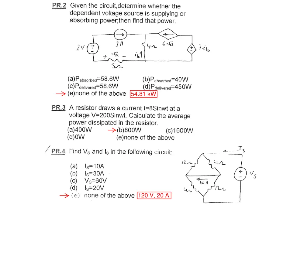
54.81 kW
120 V, 20 A
t2/3200 W, t is in s
approx
Hint: redraw as a
bridge circuit
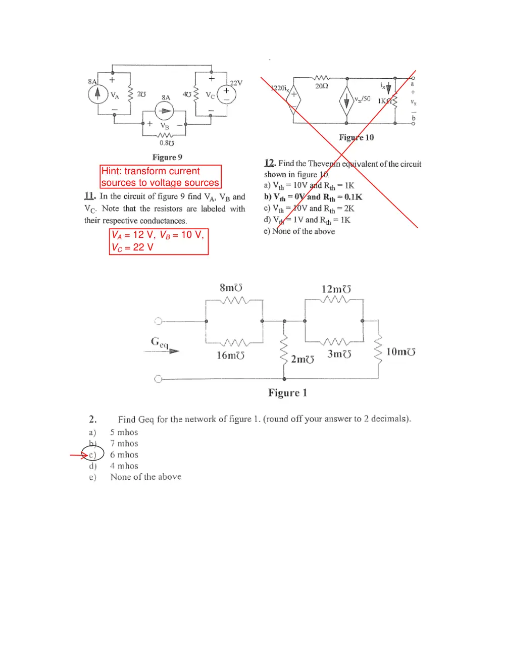
Hint: transform current
sources to voltage sources
VA = 12 V, VB = 10 V,
VC = 22 V
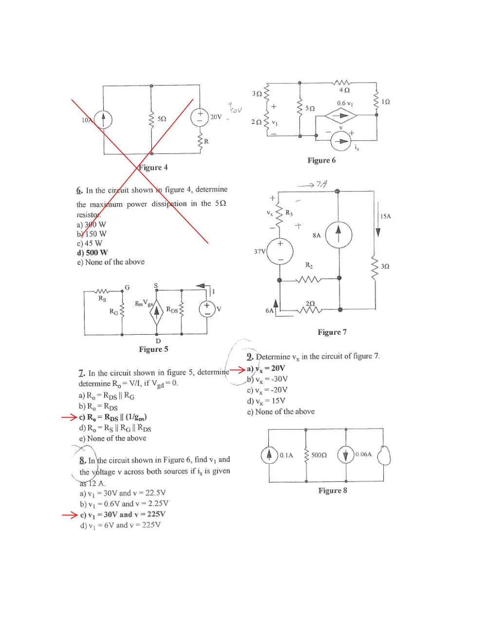
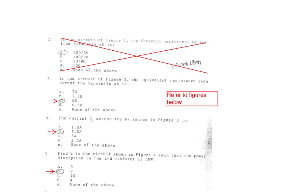
Refer to figures
below
A
50 V
8%
2. Determine Ix in the circuit shown.
+
2 Ω
–
+
–
Is = 5Ix A
2Is V
Ix
4 V
2 Ω
A. 2 A
B. 4 A
C. -2 A
D. -4 A
E. None of the above
Solution: KCL at the upper node gives a
current of 4Ix in the 2 Ω resistor; 2Is = 10Ix;
from KVL around the right mesh: 10Ix = 8Ix
+ 4, so that Ix = 2 A.
+
2 Ω
–
+
–
Is = 5Ix A
2Is V
Ix
4 V
2 Ω
4 Ix
Problem 1
Find Rab.
A) 12 ohms
B) 7.5 ohms
C) 10 ohms
D) 15 ohms
E) None of the above
Problem 2
Find the power
consumed by the 50
ohm resistor in the
circuit shown below
A) P= 0.246 W
B) P= 0.692 W
C) P= 2.358 W
D) P= 5.100 W
E) None of the
above
Problem 3
Find V0 in the 30 Ohm resistor in the circuit
shown below
A) V0 = 6 V
B) V0 = 66 V
C) V0 = 72 V
D) V0 = 78 V
E) None of the above
1
Problem 4
In the circuit shown, find the voltage denoted by Vs1
A) 300 V
B) 150 V
C) -150 V
D) 75 V
E) None of the above
Problem 5
In the circuit shown above, find the value of the load resistance RL in terms of R such
that Vo is 50 V.
A) R/3
B) 3R
C) R
D) 2R
E) None of the above
2
1. The current in a 1 μF capacitor is shown in
the figure as a function of time. The total
energy stored in μJ is:
i
10 mA
t
1 ms
4 ms
A. 40
B. 100
C. 200
D. 50
E. 25
Solution: q at 4 ms is
20
2
4
10
=
×
μC. The energy in μJ is W =
C
C
200
2
(20)
2
=
, where C is
in μF.
2. If VSRC = 10 V, determine Rx so that Ix = 0.
–
+
VSRC
5 Ω
–
+
5 V
Rx
Ix
A. 5 Ω
B. 1.25 Ω
C. 2.5 Ω
D. 1 Ω
E. 1.67 Ω
Solution: When Ix = 0,
5
5
=
+
SRC
x
x
V
R
R
, or
SRC − 5
x
V
25
=
R
Ω.
3. If R
etermine the ratio ρ /α so that I1 = I2.
Ω
E. 8 Ω
Solution:
= 10 Ω, d
A. 4 Ω
B. 10 Ω
C. 6 Ω
D. 5
R
I
I
2
1
6
− ρ
=
,
R
RI
I
1
2
6
−α
=
, or
R
RI
R
I
1
1
6
6
α
ρ
−
=
−
, which gives ρ /α = R.
–
+
–
+
ρ
α
–
+
V1
+
6 V
R
R
I2
V1
–
I2
I1
1/5
4. In the figure shown, the 24 V source having a
source resistance of 1 Ω is replaced by the
equivalent current source, the load resistance RL
being the same. If RL = 5 Ω, the ratio of the
power delivered by the ideal current source to
the power delivered by the ideal 24 V source is:
24 V
–
+
1 Ω
RL
A. 5
B. 11
C. 7
D. 14
E. 9
Solution: The power delivered by the ideal voltage source is
1
24
24
+
×
RL
. The equivalent
current source is an ideal current source of 24 A in parallel with 1 Ω. The power
delivered by the current source is
1
1
24
24
+
×
×
L
L
R
R
. The ratio of the powers is
numerically equal to RL.
– +
3VO V
_
+
VO
2 A
4 A
2 Ω
2 Ω
4 Ω
4 Ω
R
5. Determine VO in the circuit shown if R = 1 Ω
A. 18 V
B. 12 V
C. 30 V
D. 6 V
E. 24 V
Solution: The current through R is 6 A, so that
VO = 6R.
–
+
–
+
–
+
–
+
–
+
a
b
IX
0.5IX V
0.8Vab A
20 V
10 A
6. Given the source connections shown.
Determine the actual power delivered or
absorbed by each source.
Solution: IX = 0.8×20 = 16 A. Current in 20 V
source is 6 A in the direction of a voltage
rise. Voltage across dependent voltage
source is 0.5×16 = 8 V. Voltage across
2/5
dependent current source is 20 – 8 = 12 V. It follows that:
Power delivered by 20 V source is 20×6 = 120 W
Power delivered by 10 A source is 20×10 = 200 W
Power absorbed by dependent current source is 12×16 = 192 W
Power absorbed by dependent voltage source is 8×16 = 128 W
VSRC
–
+
ISRC
+
_
4 V
1.5 A
12 Ω
6 Ω
22 Ω
8 Ω
7. Determine VSRC, ISRC, and the
voltages across the four
resistors in the circuit shown.
(Four grade points for each
answer plus 1 bonus grade).
Solution: Going CCW around the
upper mesh:
VSRC
–
+
ISRC
+
_
4 V
1.5 A
12 Ω
8 Ω
6 Ω
22 Ω
I1
I2
I1+1.5
I2 -1.5
x
4 +12I1 – 8I2 = 0
Going CW around the
lower mesh:
4 – 6(I1 + 1.5) + 22(I2 –
1.5) = 0
The two equations
reduce to:
3I1 – 2I2 = -1
-3I1 + 11I2 = 19
This gives: I1 = 1 A; I2 = 2 A. Hence,
Voltage across 12 Ω resistor: 12 V
Voltage across 6 Ω resistor: 15 V
Voltage across 8 Ω resistor: 16 V
Voltage across 22 Ω resistor: 11 V
VSRC = 27 V
ISRC = 3 A.
3/5
1. Determine the power dissipated in the
circuit, assuming I = 1 A.
I
1 Ω
1 Ω
1 Ω
1 Ω
1 Ω
3 Ω
3 Ω
2 Ω
2 Ω
0.5 Ω
Solution: The 1 Ω Y is paralleled with a 3 Ω Δ,
so that it effectively becomes a 0.5 Ω Y, and the
circuit reduces to that shown. The resistance
seen by the current source is 1||1 + 2.5 = 3 Ω,
so that the power dissipated in the circuit is P =
3I2 W.
I
1 Ω
0.5 Ω
0.5 Ω
0.5 Ω
2 Ω
0.5 Ω
2. Determine the power delivered by
the 3 V source, assuming ρ = 2 V/A.
Solution: The upper node is at 5 V with
respect to the lowest node, the middle
node is at 3 V. hence, Ix = 0.5 A and the
current in the 6 Ω resistor is also 0.5 A.
The current supplied by the 3 V source
is (3 – 0.5ρ)/2 and the power delivered by the source is P = 1.5(3 – 0.5ρ) = 4.5 – 0.75ρ
W.
–
+
–
+
–
+
10 Ω
4 Ω
6 Ω
2 Ω
5 V
3 V
10 A
Ix
ρIx
–
+
10 V
R
10 Ω
2 Ω
–
+
2 V
–
+
Ix
5 V
Ix
6. Determine the power absorbed or
delivered by the dependent source
assuming R = 1 Ω.
Solution: The current in the 2 Ω resistor is
2Ix flowing downwards. From KVL in the
mesh on the left, 10 = 4Ix + 2, or Ix = 2 A.
The voltage rise Vx across the dependent
source is given by: Vx – RIx = 5, or Vx = 2R
4/5
+ 5; The power P delivered by the source is P = 2(2×R + 5).
1
5/5
6. Determine VO.
ce is replaced by a 10
x
Solution: The 2Vx sour
A source. The current in the 2 Ω resistor is Ix.
The current in the dependent source is 5 –
2Ix, so that the current in the 1 Ω resistor is
15 – Ix. From KVL around the mesh abcd, 2I
+ 15 – Ix = 4Ix, which gives Ix = 5 A. It follows
that VO = 15 – Ix = 10 V.
–
+
5 A
10 A
2 Ω
4 Ω
1 Ω
–
+
VO
Ix
5 - 2Ix
1 Ω
a
Ix
2Ix
2Ix
15 - Ix
b
d
c
–
+
5 A
2Ix
2Vx
2 Ω
4 Ω
1 Ω
Ix
–
+
VO
1 Ω
–
+
Vx
Problem 1
Find the equivalent resistance between B and E.
4Ω
5Ω
5Ω
4Ω
C
B
A
10Ω
D
12Ω
E
A) 15.11Ω
B) 16Ω
C) 8.33Ω
D) 13.61Ω
E) None of the above
Problem 2
Find V0.
2KΩ
1KΩ
2KΩ
−
+ 12V
6mA
2KΩ
+
V0
−
A) 12V
B) 7.5V
C) -12V
D) -7.5V
E) None of the above