
EECE 210 Problems, Fall 2010
American University of Beirut · Electric Circuits · 69 pages

Showing the first 10 of 69 pages. Download the PDF to see all of it.
More EECE 210 files
- Exam 1 Questions and Answers · Fall 2015Problems · with solutionView
- Exam Questions and Answers · Fall 2015Problems · with solutionView
- Exam 2 Answer and Questions · Fall 2015Problems · with solutionView
- Problems After Quiz 3 · Summer 2013ProblemsView
- Problems Exam-Solution · Spring 2013Problems · with solutionView
- Problems For Quiz 1 · Spring 2012ProblemsView
- Problems For Quiz 2 · Fall 2012ProblemsView
- Problems For Quiz 1 · Fall 2012ProblemsView
Show the text of this problems
1/1
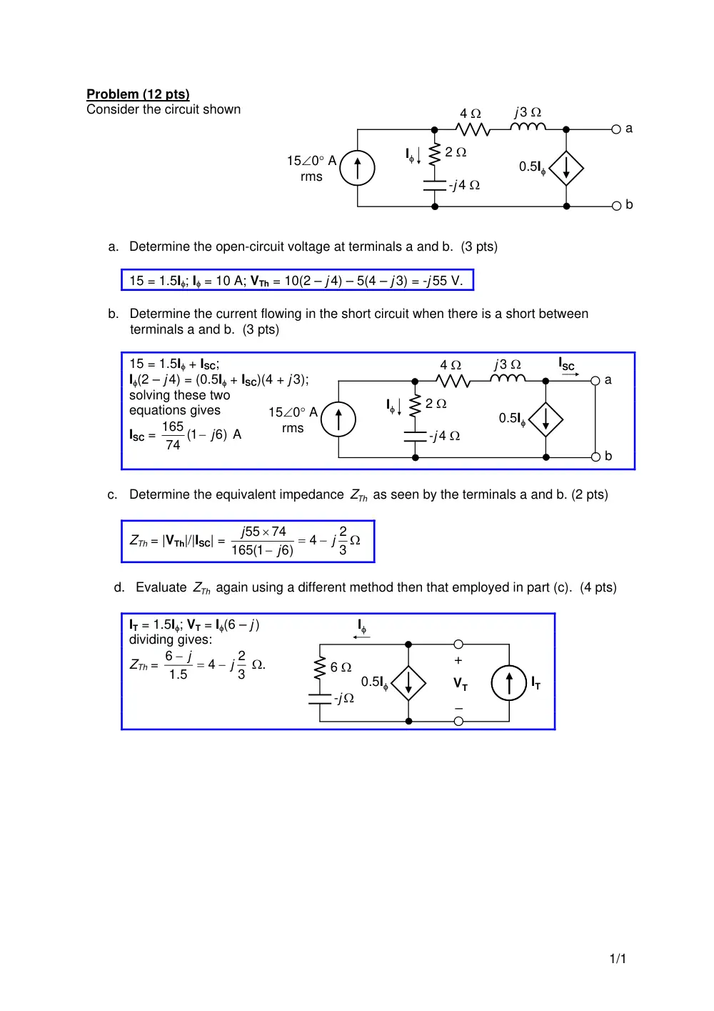
Problem (12 pts)
Consider the circuit shown
a. Determine the open-circuit voltage at terminals a and b. (3 pts)
15 = 1.5I; I = 10 A; VTh = 10(2 – j 4) – 5(4 – j 3) = -j 55 V.
b. Determine the current flowing in the short circuit when there is a short between
terminals a and b. (3 pts)
15 = 1.5I + ISC;
I(2 – j 4) = (0.5I + ISC)(4 + j 3);
solving these two
equations gives
ISC =
6)
74 (1
165
j
A
c. Determine the equivalent impedance
ZTh
as seen by the terminals a and b. (2 pts)
ZTh = |VTh|/|ISC| =
3
2
4
6)
165(1
74
55
j
j
j
d. Evaluate
ZTh
again using a different method then that employed in part (c). (4 pts)
IT = 1.5I; VT = I(6 – j )
dividing gives:
ZTh =
3
2
4
1.5
6
j
j
.
150 A
rms
2
-j 4
4
j 3
a
b
I
0.5I
150 A
rms
2
-j 4
4
j 3
a
b
I
0.5I
ISC
6
-j
I
0.5I
IT
+
–
VT
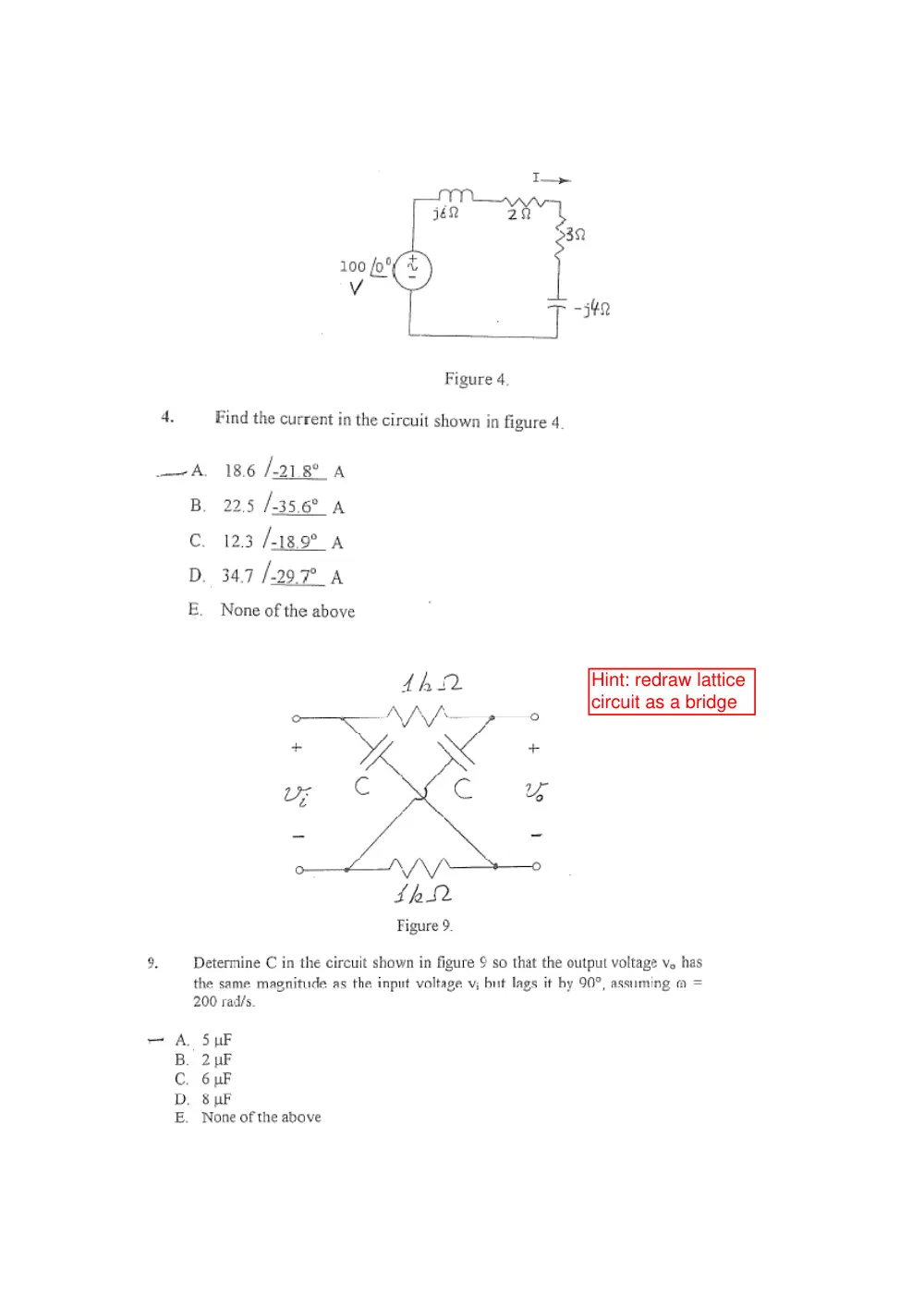
Hint: redraw lattice
circuit as a bridge
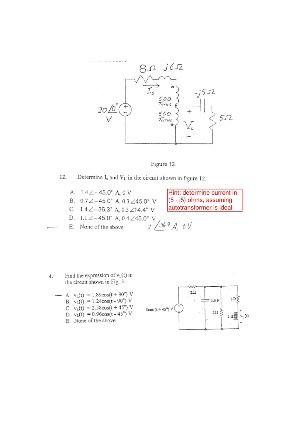
Hint: determine current in
(5 - j5) ohms, assuming
autotransformer is ideal
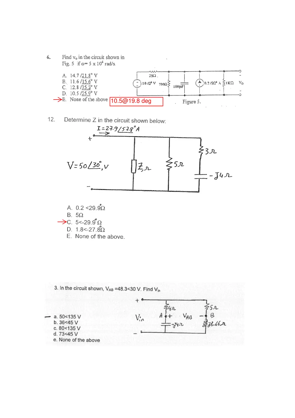
10.5@19.8 deg
Assume dot
markings are both
up
1. Find the correct node-equation for the voltage V1.
a)
0
8
6
1
=
−
+
b
a
V
V
V
b)
0
4
2
1
=
−
+
b
a
V
V
V
c)
0
1
=
+
−
b
a
V
V
V
d)
0
2
3 1
=
+
−
b
a
V
V
V
e)
0
4
7
1
=
+
−
b
a
V
V
V
4. Find the Thevenin equivalent circuit with respect to the terminals a-b. What are the
values of VTh in V and ZTh in Ω?
a) VTh =-10 V, ZTh = j10/3 Ω
b) VTh =-8 V, ZTh = j3 Ω
c) VTh =-6 V, ZTh = j14/5 Ω
d) VTh =-4 V, ZTh = j8/3 Ω
e) VTh =-2 V, ZTh = j5/2 Ω
5. What is the expression for Vx?
a) (Z1+Z2)
b) 5 Z1
c) Z1/4
d) 2 Z1
e) Z1/2
6. What is the correct set of equations for the mesh currents Ia and Ib?
a)
0
5
,0
)
4
(4
)
4
(
3
2
2
1
=
−
=
+
−
+
−
a
b
a
I
Z
Z
I
Z
Z
I
b)
0
2
,0
)
2
(2
)
2
(
3
2
2
1
=
−
=
+
−
+
−
a
b
a
I
Z
Z
I
Z
Z
I
c)
0
1
,0
)
(
)
(
3
2
2
1
− =
=
+
−
+
−
a
b
a
I
Z
Z
I
Z
Z
I
d)
0
1/ 2
,0
)
(
)
2
(
3
2
2
1
=
−
=
+
−
+
−
a
b
a
I
Z
Z
I
Z
Z
I
e)
0
1/ 4
,0
)
(
)
4
(
3
2
2
1
=
−
=
+
−
+
−
a
b
a
I
Z
Z
I
Z
Z
I
17. If a capacitor with impedance Z2 is connected in parallel to a load Z1 = 300 +j450 Ω.
What should be Z2 in ohms so that the equivalent load is purely resistive?
a) -928.6 j
b) -1112.5 j
c) -650 j
d) -750 j
e) None of the above
22. Assuming that the voltage V across inductance L1 is as shown in figure below and
that the mutual inductance between
‐
L1 and L2 is M12
‐
L1 and L3 is M13
‐
L2 and L3 is M23
Use the mesh technique to find the expression of the voltage V.
a) V=- L1dI1/dt - M12dI1/dt + M13dI2/dt
b) V=- L1dI1/dt + M12dI1/dt + M13dI2/dt
c) V=- L1dI1/dt + M12dI1/dt - M13dI2/dt
d) V=- L1dI1/dt + M12dI1/dt + M13dI2/dt
e) None of the above
1
Problem 1
Find Zth across a and b
A) Zth = 3.85- j 0.77
B) Zth = 1.65- j 5.50
C) Zth = 5.29- j 8.82
D) Zth = 6.50- j 1.65
E) None of the above
Problem 2
What are the impedances in this circuit if v(t)=20 cos(10t+50o) Volts and i(t)=50cos(10t+20o) Amperes.
A) 10 j j
B) 10 j1.0j
C) 10 j j
D) 10 j j
E) None of the above
2
Problem 3
Find the node equations for the following circuit
A)
0
2.0
.0 133
2.0
1.0
0
2.0
8.3
.0 05
05
.0
0
.6 43
.7 66
1.0
.0 05
5.0
15
.0
3
2
1
3
2
1
3
2
1
V
j
V
j
V
V
j
V
j
V
j
V
V
V
j
B)
0
2.0
.0 0833
2.0
05
.0
0
2.0
8.3
1.0
1.0
0
.6 43
.7 66
.0 05
1.0
5.0
15
.0
3
2
1
3
2
1
3
2
1
V
j
V
j
V
V
j
V
j
V
j
V
V
V
j
C)
0
2.0
.0 133
2.0
1.0
0
2.0
8.3
.0 05
05
.0
0
15.32
12.85
1.0
.0 05
2.0
15
.0
3
2
1
3
2
1
3
2
1
V
j
V
j
V
V
j
V
j
V
j
V
V
V
j
D)
0
2.0
.0 0833
2.0
05
.0
0
2.0
8.3
1.0
1.0
0
15.32
12.85
.0 05
1.0
2.0
15
.0
3
2
1
3
2
1
3
2
1
V
j
V
j
V
V
j
V
j
V
j
V
V
V
j
E) None of the above
3
Problem 4
Find V0 (t) given =120 rad/sec.
A) V0 = -0.99 cos( 120t +94.29. o ) Volts
B) V0 = -1.99 cos( 120t +194.29o ) Volts
C) V0 = -1.99 cos( 120t -25.7 o ) Volts
D) V0 = -0.99 cos( 120t -115.71 o ) Volts
E) None of the above
Problem 5
Find io in the circuit above.
A)
.8 178 104.620
B)
23.14 89.620
C)
16.36 104.620
D)
11.57 89.620
E) None of the above
4
Problem 6
Given the circuit above, what are the two mesh equations?
A)
0
50
50
190
;0
190
280
100
40
120
2
1
2
1
0
i
j
i
j
i
i
j
B)
0
50
50
250
;0
250
400
100
40
120
2
1
2
1
0
i
j
i
j
i
i
j
C)
0
50
50
150
;0
150
200
100
40
120
2
1
2
1
0
i
j
i
j
i
i
j
D)
0
50
50
210
;0
210
320
100
40
120
2
1
2
1
0
i
j
i
j
i
i
j
E) None of the above
Problem 7
In the circuit shown above, what is the value of the reflected impedance of the 50 ohms resistor from the
primary to the secondary side?
A)
B)
C)
D)
E) None of the above
5
Problem 8
In the circuit shown above, find the Thevenin voltage across a,b
A)
V
39.800
76.82
B)
V
55 0. 0
57 3.
C)
V
63 0. 0
28 6.
D)
V
48 3. 0
65.99
E) None of the above
Problem 9
For the same circuit of previous problem, find Zth across a,b
A) Zth= 4.9- j4.1
B) Zth= 1.08- j2.12
C) Zth= 4.7- j6.71
D) Zth= 3.7- j5.1
E) None of the above
6
Problem 10
Find the Thevenin equivalent resistance and capacitance/inductance with respect to the terminals a,b in
the circuit shown above
A) R = L
B) R = L
C) R = L
D) R = L
E) None of the above
Problem 11
In the circuit shown above, find the value of the impedance Z if
.
A
j
V
j
V
j
g
g
30
20
, and I
50
100
, V
30
40
V1
A) j
B) 58+j14
C) 68+j24
D) 5+j20
E) None of the above
7
Problem 12
Find the input impedance Zi at the terminals a,b in the circuit shown above
A)
C
j
jL
Zi
25
1
40
B)
C
j
jL
Zi
40
1
25
C)
C
j
jL
Zi
40
1
15
D)
C
j
jL
Z i
15
1
40
E) None of the above
Problem 13
In the circuit of the previous problem, find the frequency such that the input impedance Zi is purely
resistive.
A)
rad/s
1
1000
40
1
L
C
C
B)
rad/s
1
1000
25
1
L
C
C
C)
rad/s
1
600
40
1
L
C
C
D)
rad/s
1
600
15
1
L
C
C
E) None of the above
8
Problem 14
In the circuit shown above, it is given that R=1 , and Vs=
0
10 volts. Find the current i1 as indicated.
A)
53.130
8
A
B)
53.130
.7 07
A
C)
450
.7 07
A
D)
450
8
A
E) None of the above
4
Problem 5
Find the magnitude of the Thevenin Voltage Vth across terminals a,b in the circuit above. Given A=1/4.
A) 15.0 V
B) 37.5 V
C) 14.29 V
D) 7.15 V
E) None of the above
5
Problem 7
In the circuit shown above, given
V
90
48
0
∠
Vs =
,
Ω
+
=
4
3
1
j
Z
,
Ω
−
=
6
8
2
j
Z
,
Ω
−
=
4
3
3
j
Z
and
Ω
+
=
6
8
4
j
Z
. The Thevenin equivalent circuit values for the voltage souce and the internal impedance
across terminals e and f are:
A)
V
0
14
∠ 0
,
Ω
−
5.3
5.3
j
B)
V
0
50
∠ 0
,
Ω
+
5.2
5.2
j
,
C)
V
0
14
∠ 0
,
.7 29 Ω
D)
V
0
50
∠ 0
,
10.42 Ω
E) None of the above
Problem 8
In the circuit shown above, the phasor form of the current I in amperes is:
A)
V
45 0. 0
.1 833
∠ −
B)
V
45 0. 0
.0 917
∠ −
C)
V
53.130
5.1
∠ −
D)
V
53.130
0.3
∠ −
E) None of the above
I
8
Problem 12
Find V0 if the source voltage is Vs = 20∠ 60 o Volts.
A) 14.14 ∠ 15o V
B) 7.07∠ 15 o V
C) 20∠ 60 o V
D) 10 ∠ 60 o V
E) None of the above
Problem 13
Find V0.
A) 400 ∠ 0 V
B) - 400 ∠ 0 V
C) 100 ∠ 0 V
D) - 100 ∠ 0 V
E) None of the above
+
V0
+
–
–
Vs
-5j
5j
50
-2j
2j
5
10j
2
2j
–
+
5:10
2:1
+
V0
–
10Ω
10Ω
50Ω
20∠50 V
10∠0 A
j40sqrt(2) rms
3. ~ ~ T h e v ~ ~ c e t o t h . e l & o f t h e ~ T l - T 2 o f ~ ~
in figure-
a.
15~50' Q
t
b. 5 + 5 j 6 2
c.
I.O8G+ 2.5351 fi
I
d. 9.69~51.07~
SZ
e. None of the above.
and L are unknown Load 1 absorbs a complex power
absorbs a complex power of 1 0 0 ~ 4 5 ~
VA. Determine Rz
rms.
a 1.60cos(2f) V.
b. l.GOsin(t) V.
c. 3.2ms(f) V.
d. 2.26cos(t) V.
' Nom of the above.
5. Find the vohage v, (t) across the
6. Two lnypsdances 2, = 9 . 8 ~
- 78' B and 2, = 1 ~ 5 ~ 2 1 . 8 '
fl, are connected in p d l d
and the combinatIan in series with an impedance 2, =5.&3%.
E this circuit is
corn across a IOQ-V source (m),
how much average powezwill be supplied by the
SOurCe.
a 980.8 W.
b. 490 W.
c. 1960 W.
d. 1391.6 W.
e. None of the above.
4. How mu& complex power is delivered by the 5630' A (rms) currd source to fhe
circuit shown in figure.
a 7.5~137.48' VA.
b. 0 VA.
C. 100 VA
d. 15.35~137.48~
VA.
e- None of the above.
- -
- -
,r'
. - -
- -
e. None of the above.
10. In problem 9, find the average power delivered to the 375 a resistor.
a. 99.2 W.
b. 50.3 W.
c. 49.2 W.
d. 62.7 W.
e. None of the above.
11. Calculate the reading of the two wattmeters fW,+
WZ)
in the circuit shown in figure. The
value of Z, = 60L30° a.
c. -33.2 kW.
d. -15.4 kW.
e. None ofthe above.
6 - - - - t
Find
tbe steady-state
expression
for
v,(r)
in
the
circuit
shown
if
a 4cos(SOOQ) V .
b. Scos(5000t) V .
c. 16cos(5000t) V .
d. 12cos(S000t) V .
e. None of the above.
22.3cos(5,000t + 29.7)
1/2
Consider the circuit shown
Problem 8 ( 14 pts)
a. For ZL = 3 – j 5.2 Ω ,determine the average power developed by the voltage source
and the average power absorbed by the load. (4 pts)
–
+
–
+
4 Ω
-j 7 Ω
8 Ω
j5.78 Ω
12∠0° V
rms
ZL
VTh =
1.74
9
7
12
7
12 8
j
j
j
−
=
−
−
V;
|VTh| = 9.18 V;
IL = VTh /6
0.29
1.5
− j
=
A;
V1 = (3 – j 0.58)IL = 4.68 +j 0 V
ISRC =
=
−
4
4.68
12
1.83 +j 0 A
PSRC = V1ISRC = 12×1.83 ≅ 22 W;
3
4
(9.18)
2
×
PL =
≅ 7 W.
–
+
–
+
4 Ω
-j 7 Ω
8 Ω
j5.78 Ω
12∠0° V
rms
-j 5.2 Ω
3 Ω
V1
IL
ISRC
9
Problem 14
It is given that the complex power of L1 is 5+j10 VA. It is also given that L2 absorbs 20W at lagging
power factor of 0.8. What is the phase difference between I and V as shown in figure?
A) 45.00o
B) 39.81o
C) 63.33 o
D) 60.00 o
E) None of the above.
Problem 15
What is the impedance of a load if it absorbs 20KVAR at lagging power factor of 0.6 when a current of
magnitude 50 A rms flows through it?
A) 6 + 8j ohms
B) 3 + 4j ohms
C) 4+ j3 ohms
D) 8+ j6 ohms
E) None of the above.
–
+
5Ω
100∠20 Vrms
L1
L2
+
V
_
I
1. If M = 5 mH, determine the ratio v1/v.
M
40 mH
60 mH
i
_
+
v1
_
+
v
Solution: Leq = L1 + L2 – 2M;
dt
di
L
v
eq
=
;
dt
M di
dt
L di
v
−
=
1
1
;
hence,
=
−
+
−
=
M
L
L
M
L
v
v
2
2
1
1
1
M
M
2
100
60
−
−
2. Determine VO, given that I = 1∠0° A and ω = 10 rad/s.
1 H
k =
0.5
I
VO
_
+
1 H
Solution:
0.5
1 2
=
=
k L L
M
H; secondary voltage is jωMI,
with the dotted terminal positive with respect to the
undotted terminal. Hence, VO = -jωMI = -j10×0.5I = -j5I.
3. The lamp glows brighter when the dots are at coil terminals
200
turns
100
turns
1
1′
2
2′
12 V
ac
Solution: The lamp glows brighter when the voltage across it is
largest. This occurs when the voltages across the windings are
additive, that is, when the dots are at terminals 1 and 2 or 1′ and 2′.
4. Determine the reactive power absorbed in the circuit,
given that I = 1∠0° A rms.
Solution: The equivalent series impedance is
5
5
5
5
5
5)
5(5
j
j
j
j
j
+
=
−
+
−
. The reactive power is 5|I|2 VAR. As a
check, the current in the capacitive branch is
5
5
5
5
j
j
j
−
+
I = jI; the reactive power absorbed
by the capacitor is -5|jI|2 = -5|I|2 VAR. The current in the inductive branch is
j5 Ω
-j5 Ω
5 Ω
I
5
5
5
5
5
j
j
j
−
+
−
I = (1
– j)I =
2 ∠-45°I; the reactive power absorbed by the inductor is 5|
2
assuming VSRC = 200∠0° V rms.
I|2 = 10|I|2 VAR. The
total reactive power absorbed is 10|I|2 – 5|I|2 = 5|I|2 VAR.
5. In the circuit shown, L1 consumes
160 W at 0.8 p.f. lagging and L2
consumes 320 VAR at 0.6 p.f.
lagging. Determine I when XC is
chosen for unity power factor,
–
XC
VSRC
+
L1
L2
I
1/5
So
nce seen by the source is zero and the source applies
lution: Ay unity p.f. the total reacta
only real power. The real power consumed by L2 is
240
0.6
320
=
×
W. The total real
.8
0
power supplied by the load is 160 + 240 = 400 W. The current is
o
o
0
0
∠
=
∠
SRC
SRC
V
V
A
rms.
. Derive the time-domain expression for vC,
400
400
6
_
+
vC
5ix
3 Ω
_
+
2 mH
100 μF
2 mH
vSRC
ix
given that vSRC = 10sin(2,000t) V.
Solution: ωL = 2×103×2×10-3 = 4 Ω;
5
10
100
10
2
6
3
×
×
×
−
ωC
SRC = 10∠0°.
The node-voltage method can be a
x – V
5(10 – VC)/j4
at
. Derive VTh and ZTh as
s
.
Ω; ωL2
1
1
=
=
Ω; V
pplied,
the circuit being as shown. At the middle node:
VC/-j5 + (VC – Vx)/j4 + (VC – 10)/j4 = 0
5Ix
3 Ω
_
+
10∠0°
Ix
-j5 Ω
j4 Ω
j4 Ω
VC
Vx
At the right-hand node:
(V
C)/j4 + (Vx – 10)/3 = 5Ix =
Solving, VC = 11.98 + j1.44 = 12.1∠6.86°, so th
vC = 12.1sin(2,000t + 6.86°) V.
–
+
vSRC
5 Ω
50 μF
20 mH
30 mH
20 mH
a
b
1:2
7
seen between terminal
ab, given that vSRC =
10cos(1,000t + 45°) V
Solution: ωL1 =
103×30×10-3 = 30
= ωM =103×20×10-3 = 20
Ω;
6
3
10
50
10
−
×
×
C
ω
= 20 Ω; VSRC = 10∠45°.
will be as shown, where ω(L1 – M
0 Ω and is omitted.
1
1 =
The circuit in the
frequency domain
The j20 Ω in parallel with -j20 Ω is effectively an open circuit. The current in the (5 + j10) Ω
impedance is zero, Vcd = 10∠45°, and Vab = VTh = 20∠45°.
) = 10 Ω; ω(L2 – M) =
–
+
5 Ω
a
b
1:2
j20 Ω
-j20 Ω
c
d
10∠45°
j10 Ω
2/5
If the independent voltage source is replaced by a short circuit, the impedance on the
primary side is (5 + j10) Ω and ZTh = 4(5 + j10) = 20 + j40 Ω.
3. Determine the
impedance seen
by the source,
assuming a = 2.
Solution: Reflection
of the (5 – j5) Ω
through the RH transformer gives (20 – j20) Ω. The impedance on the secondary side of the
LH transformer is (25 – j10) Ω. Reflected to the primary side, this becomes (25 – j10)/a2 Ω.
–
+
4∠0° V
5 Ω
j10 Ω
2:1
5 Ω
-j5 Ω
1:a
4. If vsrc = 10cos(1,000t) V, determine the energy
stored in the circuit in the sinusoidal steady state
at t = 0, assuming C = 1 μF.
1H
1H
k = 0.5
–
+
vsrc
C
Solution: At t = 0, the voltage across C is 10 V and
the current through the inductors is zero, being
proportional to the integral of vsrc. The energy stored
is W =
2 =
2
1Cv
50C.
–
+
10∠0° V
8 Ω
6 Ω
-j5 Ω
–
+
30∠0° V
-j10 Ω
R
Rx
I
5. Determine Rx given that I = 0
and R = 2 Ω.
Solution: Since I = 0, the voltage
across Rx is 10 V, and the same
current
R
o
o
10 0
30 0
∠
−
∠
flows
through R and Rx. It follows that
–
+
5∠0° V
R
–
+
2∠0° V
1:2
1:2
RL
10
20
R Rx =
, or
2
Rx = R
.
7. Determine the maximum power that
can be delivered to RL, assuming R
= 0.5 Ω.
Solution: The primary voltage of the
upper transformer is always 1 V. On
3/5
open circuit, the source current is zero, the primary voltage is 5 – 1 = 4 V, and VTh = 8 V. On
short circuit, the primary voltage of the lower transformer is zero, the source current is (5 –
1)/R and the short circuit current is 2/R. This gives, RTh = 4R. The maximum power delivered
is (8)2/(4×4R) = 4/R.
-j30 Ω
L
RLine
Supply
voltage
8. Given that the load L consumes 1200 W at 0.8
p.f. lagging and the magnitude of the voltage
across L is 300 V rms. Determine the power
dissipated in the resistance Rline, if Rline = 0.5 Ω.
Solution: The reactive power absorbed by the load
is
900
0.6
0.8
=
1200 ×
VAR. The reactive power absorbed by the capacitor is
3000
30
2
= −
−
V
VAR. The total complex power is 1200 + j(900 – 3000) = 1200 – j2100 VA. The magnitude of
the line current
65
300
(2100)
(1200)
2
2
=
+
A. The power dissipated in Rline is 65Rline.
9. Two identical coils, each having an inductance of 10 mH, are connected in series. When
the connections to one of the coils are reversed, the total inductance is multiplied by a
factor a. Determine the coupling coefficient of the coils.
Solution: (10 + 10 + 2M) = a(10 + 10 –
2M); 2M(a + 1) = 20(a – 1);
–
+
10∠0° V
R
2 Ω
–
+
400
turns
100
turns
200
turns
4∠0° V
Ix
1
)1
10(
+
−
=
a
a
M
;
1
)1
(
10
+
−
=
=
a
a
M
k
10. Determine Ix, assuming R = 4 Ω.
Solution: The voltage across all
windings is zero. Hence, I1 = R
10 A, and
I2 =
2
2
4 =
A. Setting the net mmf to
zero, 400I1 – 100I2 + 200I3 = 0, or
–
+
10∠0° V
R
2 Ω
–
+
400
turns
100
turns
200
turns
4∠0° V
Ix
I1
I2
I3
2
2
10
4
+
−
×
R
I3 = 0, which gives I3 =
R
1− 20
; IX = I2 – I3 =
R
1+ 20
.
4/5
11. Determine the frequency at which maximum
power is dissipated in the 10 Ω resistor,
assuming L = 1 H.
–
+
L
8 Ω
10 Ω
1 F
5∠0° V
5/5
Solution:
ω
ω
1 = 1
C
Ω. Maximum power is
dissipated in the 10 Ω resistor when XL = -XC,
which gives ωL = ω
1 , or
L
ω = 1
rad/s.
1. If M = 5 mH, determine the ratio v1/v.
M
40 mH
60 mH
i
_
+
v1
_
+
v
Solution: Leq = L1 + L2 – 2M;
dt
di
L
v
eq
=
;
dt
M di
dt
L di
v
−
=
1
1
;
hence,
=
−
+
−
=
M
L
L
M
L
v
v
2
2
1
1
1
M
M
2
100
60
−
−
2. Determine VO, given that I = 1∠0° A and ω = 10 rad/s.
1 H
k =
0.5
I
VO
_
+
1 H
Solution:
0.5
1 2
=
=
k L L
M
H; secondary voltage is jωMI,
with the dotted terminal positive with respect to the
undotted terminal. Hence, VO = -jωMI = -j10×0.5I = -j5I.
3. The lamp glows brighter when the dots are at coil terminals
200
turns
100
turns
1
1′
2
2′
12 V
ac
Solution: The lamp glows brighter when the voltage across it is
largest. This occurs when the voltages across the windings are
additive, that is, when the dots are at terminals 1 and 2 or 1′ and 2′.
4. Determine the reactive power absorbed in the circuit,
given that I = 1∠0° A rms.
Solution: The equivalent series impedance is
5
5
5
5
5
5)
5(5
j
j
j
j
j
+
=
−
+
−
. The reactive power is 5|I|2 VAR. As a
check, the current in the capacitive branch is
5
5
5
5
j
j
j
−
+
I = jI; the reactive power absorbed
by the capacitor is -5|jI|2 = -5|I|2 VAR. The current in the inductive branch is
5
5
5
5
5
j
j
j
−
+
−
I = (1
– j)I =
2 ∠-45°I; the reactive power absorbed by the inductor is 5|
2 I|2 = 10|I|2 VAR. The
total reactive power absorbed is 10|I|2 – 5|I|2 = 5|I|2 VAR.
j5 Ω
-j5 Ω
5 Ω
I
5. In the circuit shown, L1 consumes
160 W at 0.8 p.f. lagging and L2
consumes 320 VAR at 0.6 p.f.
lagging. Determine I when XC is
chosen for unity power factor,
assuming VSRC = 200∠0° V rms.
–
XC
VSRC
+
L1
L2
I
1/7
Solution: Ay unity p.f. the total reactance seen by the source is zero and the source applies
only real power. The real power consumed by L2 is
240
0.6
0.8
320
=
×
W. The total real
power supplied by the load is 160 + 240 = 400 W. The current is
o
o
0
400
0
400
∠
=
∠
SRC
SRC
V
V
A
rms.
_
+
vC
5ix
3 Ω
_
+
2 mH
100 μF
2 mH
vSRC
ix
6. Derive the time-domain expression for vC,
given that vSRC = 10sin(2,000t) V.
Solution: ωL = 2×103×2×10-3 = 4 Ω;
5
10
100
10
2
1
1
6
3
=
×
×
×
=
−
ωC
Ω; VSRC = 10∠0°.
The node-voltage method can be applied,
the circuit being as shown. At the middle node:
VC/-j5 + (VC – Vx)/j4 + (VC – 10)/j4 = 0
At the right-hand node:
(Vx – VC)/j4 + (Vx – 10)/3 = 5Ix = 5(10 – VC)/j4
Solving, VC = 11.98 + j1.44 = 12.1∠6.86°, so that
vC = 12.1sin(2,000t + 6.86°) V.
7. Derive VTh and ZTh as
seen between terminals
ab, given that vSRC =
10cos(1,000t + 45°) V.
Solution: ωL1 =
103×30×10-3 = 30 Ω; ωL2
= ωM =103×20×10-3 = 20
Ω;
6
3
10
50
10
1
1
−
×
×
ωC =
= 20 Ω; VSRC = 10∠45°.
The circuit in the
frequency domain will be as shown, where ω(L1 – M) = 10 Ω; ω(L2 – M) = 0 Ω and is omitted.
The j20 Ω in parallel with -j20 Ω is effectively an open circuit. The current in the (5 + j10) Ω
impedance is zero, Vcd = 10∠45°, and Vab = VTh = 20∠45°.
5Ix
3 Ω
_
+
10∠0°
Ix
-j5 Ω
j4 Ω
j4 Ω
VC
Vx
–
+
vSRC
5 Ω
20 mH
50 μF
20 mH
30 mH
a
b
1:2
–
+
5 Ω
a
b
1:2
j20 Ω
-j20 Ω
c
d
10∠45°
j10 Ω
2/7
If the independent voltage source is replaced by a short circuit, the impedance on the
primary side is (5 + j10) Ω and ZTh = 4(5 + j10) = 20 + j40 Ω.
3. Determine the
impedance seen
by the source,
assuming a = 2.
Solution: Reflection
of the (5 – j5) Ω
through the RH transformer gives (20 – j20) Ω. The impedance on the secondary side of the
LH transformer is (25 – j10) Ω. Reflected to the primary side, this becomes (25 – j10)/a2 Ω.
–
+
4∠0° V
5 Ω
j10 Ω
2:1
5 Ω
-j5 Ω
1:a
4. If vsrc = 10cos(1,000t) V, determine the energy
stored in the circuit in the sinusoidal steady state
at t = 0, assuming C = 1 μF.
1H
1H
k = 0.5
–
+
vsrc
C
Solution: At t = 0, the voltage across C is 10 V and
the current through the inductors is zero, being
proportional to the integral of vsrc. The energy stored
is W =
2 =
2
1Cv
50C.
–
+
10∠0° V
8 Ω
6 Ω
-j5 Ω
–
+
30∠0° V
-j10 Ω
R
Rx
I
5. Determine Rx given that I = 0
and R = 2 Ω.
Solution: Since I = 0, the voltage
across Rx is 10 V, and the same
current
R
o
o
10 0
30 0
∠
−
∠
flows
through R and Rx. It follows that
10
20
R Rx =
, or
2
Rx = R
.
–
+
5∠0° V
R
–
+
2∠0° V
1:2
1:2
RL
7. Determine the maximum power that
can be delivered to RL, assuming R
= 0.5 Ω.
Solution: The primary voltage of the
upper transformer is always 1 V. On
3/7
open circuit, the source current is zero, the primary voltage is 5 – 1 = 4 V, and VTh = 8 V. On
short circuit, the primary voltage of the lower transformer is zero, the source current is (5 –
1)/R and the short cir
cuit current is 2/R. This gives, RTh = 4R. The maximum power delivered
(8)2/(4×4R) = 4/R.
8.
The reactive power absorbed by the load
is
Given that the load L consumes 1200 W at 0.8
p.f. lagging and the magnitude of the voltage
across L is 300 V rms. Determine the power
dissipated in the resistance Rline, if Rline = 0.5 Ω.
Solution:
is
900
0.6
0.8
=
×
VAR. The reactive power absorbed by the capacitor is
-j30 Ω
L
RLine
Supply
voltage
1200
3000
30
= −
−
2
V
VAR. The total complex power is 1200 + j(900 – 3000) = 1200 – j2100 VA. The magnitude of
ent
65
300
(2100)
(1200)
2
2
=
+
the line curr
A. The power dissipated in Rline is 65Rline.
9.
n
l inductance is multiplied by a
ficient of the coils.
(10 + 10 –
2M); 2M(a + 1) = 20(a – 1);
Two identical coils, each having an inductance of 10 mH, are connected in series. Whe
the connections to one of the coils are reversed, the tota
factor a. Determine the coupling coef
Solution: (10 + 10 + 2M) = a
1
)1
10(
+
−
=
a
a
M
;
1
)1
(
10
+
−
=
=
a
a
M
k
Ω.
windings is zero. Hence, I1 =
–
+
10. Determine Ix, assuming R = 4
Solution: The voltage across all
R
I2 =
10 A, and
2
2 =
100I2 + 200I3 = 0, or
4
A. Setting the net mmf to
zero, 400I1 –
2
2
10
4
+
−
×
R
I3 = 0, which gives I3 =
R
1− 20
; IX = I2 – I3 =
R
1+ 20
.
10∠0° V
R
2 Ω
–
+
400
turns
100
turns
200
4∠0° V
Ix
turns
–
+
10∠0° V
R
2 Ω
–
+
400
turns
100
turns
200
turns
4∠0° V
Ix
I1
I2
I3
4/7
11.
assuming L = 1 H.
Determine the frequency at which maximum
–
+
L
8 Ω
10 Ω
1 F
5∠0° V
power is dissipated in the 10 Ω resistor,
Solution:
ω
ω
1 = 1
Ω. Ma
C
ximum power is
issipated in the 10 Ω resistor when XL = -XC,
d
which gives ωL = ω
1 , or
L
rad/s.
dissipated in R if R =
Solution: With either of the
= 1
ω
15. Determine the total power
1 Ω.
10cos100t V acting alone, iR1 =
1
5
2
2
2
2
10
+
=
+
×
+
R
R
R
R
. The
V sources, with the 10cos200t
2 Ω
2 Ω
R
–
+
10cos100t V
2 +
current due to both 10cos100t
V source set to zero, is
R + 1
10
and the power dissipated in R is (
)
(
)
2
2
1
50
1
2
100
+
=
+
R
R
R
R
. With the
10cos200t V source acting alone, iR3 =
1
10
R +
, and the power dissipated in R is
(
)
(
)
2
2
1
50
1
2
100
+
=
+
R
R
R
R
. The total power dissipated in R is (
)
2
1
100
+
R
R .
6. Determine iO, given that
VSRC1 is 15 V dc and VSRC2 =
10cos(3,000t) V.
1
–
+
–
+
10cos100t V
10cos200t V
–
+
2Vx
2 Ω
5 Ω
5 Ω
–
+
Vx
VSRC2
–
+
2 Ω
10 mH
50 μF
V
+
SRC1
–
iO
5/7
Solution: With VS
d
RC1 applied an
VSRC2 set to zero, the circuit
ecomes as shown. 15 = 3Vx, so
Vx = 5 V and
–
+
2Vx
2 Ω
5 Ω
–
+
Vx
5 Ω
2 Ω
15 V
–
+
IO1
b
1
5
1
= −
−
=
x
O
V
I
that
A.
With VSRC2 applied and VSRC1
comes as
shown. It follows that: -2V = Vx +
set to zero, the circuit be
x
–
+
C
jX
2Vx
, or
0
2
3
=
⎟⎠
⎜⎝
C
x
jX
⎟
⎜⎛
+
V
, which
ives Vx = 0. Hence, IO2
⎞
g
o
o
2 0
5
10 0
∠
=
∠
=
A. Thus,
iO = -1 + 2cos(3,000t) A.
17. Determine k so that the input resistance is
purely resistive.
transformer by
actance is
Solution: Disregarding the 10 Ω resistance
and replacing the linear
its T-
equivalent circuit, the circuit becomes as
shown. The input re
(
)
0
20
20
10
=
+
−
+
j
jX
j
jX
jX
j
M
M
M
, or
0
20
10
2
=
−
−
+
M
M
M
X
X
X
, which gives
200 = 10 2
XM =
. Hence,
=
=
=
2
1
400
10 2
k
0.71.
2Vx
IO2
2 Ω
5 Ω
5 Ω
–
+
Vx
10∠0° V
–
+
jXL
2 Ω
jXC
10 Ω
k
j40 Ω
j10 Ω
-j20 Ω
Zin
j(40 + XM) Ω
j(10 + XM) Ω
-j20 Ω
-jXM Ω
6/7
7/7
8. Determine Z so that maximum power is
transferred to it and calculate this
power given that the source voltage is
10 V peak value.
s
=
ancel
peak va
h
re as shown. F
KVL: 10∠0° – 5(I + I/2) – 5(I –
I/2) = 0. Again, the terms
1
Solution: We will determine TEC as seen
by Z. On open circuit, the currents are a
shown. From KVL: 10∠0° – 5I/2 + 5I/2
VTh. In This particular problem, the
voltages across the 5 Ω resistors c
out. Hence, VTh = 10∠0° V
When Z is replaced by a s
circuit, the currents a
sc
sc
involving I cancel out. Hence, Isc
= 1∠0° A, and ZTh =
lue
ort
rom
10
1∠0
o
10 0
=
∠
o
Ω. It follows that for
aximum power transfer, Z = 10
. The power dissipated in the
load is
m
Ω
1.25
10
4
1
2
2
=
×
⎟⎟
⎠
⎞
⎜⎜
⎝
⎛
VTh
W.
–
+
10∠0° V
1:2
5 Ω
j2 Ω
5 Ω
Z
–
+
10∠0° V
5 Ω
j2 Ω
1:2
5 Ω
–
+
VTh
I
I/2
I/2
I/2
–
+
10∠0° V
j2 Ω
1:2
5 Ω
5 Ω
I
I/2
ISC – I/2
Isc
Isc + I/2
Problem 1
Given 3 elements R = 10KΩ, L = 10mH and C = 625nF powered by a source
v = 90sin(10, 000t + π
4) (V). Find the impedance of each element ZR, ZL and ZC.
A) ZR = 10KΩ, ZL = 100jΩ, ZC = −160jΩ
B) ZR = 10KΩ, ZL = 10jΩ, ZC = −16jΩ
C) ZR = 10jKΩ, ZL = 10jΩ, ZC = −1600jΩ
D) ZR = 10KΩ, ZL = 10jΩ, ZC = −160jΩ
E) None of the above
Problem 2
Find the Thevenin equivalent voltage between A and C. (Impedances are in Ω)
C
−5j
−2j
−3j
10j
20j
B
A
50j
5j(A)
10 + 10j(A)
10 + 10j(A)
35Ω
A) 285-190j V
B) -741+494j V
C) -741-494j V
D) 285+190j V
E) None of the above
Problem 3
Find the Thevenin equivalent voltage between A and B.
−
+
10j(V )
10Ω
i1
−5jΩ
20Ω
2i1
B
A
A) 39.7V ∠21.6o
B) 18.6V ∠7.1o
C) 18.6V ∠ − 7.1o
D) 39.7V ∠ − 21.6o
E) None of the above
Problem 4
Find the nature of Z such that the Thevenin equivalent impedance between A and B is
1Ω.
10A
jΩ
Z
2jΩ
A
B
A) 0.8 − 1.4jΩ
B) 0.8 + 1.4jΩ
C) 0.5 − 2.5jΩ
D) 0.5 + 2.5jΩ
E) None of the above
Problem 5
Find the Thevenin voltage between A and B.
10jΩ
10Ω
5jΩ
5j(A)
A
B
A) 50+25j V
B) -100+50j V
C) 100+50j V
D) -50+25j V
E) None of the above
Problem 6
Find the Thevenin impedance between A and B.
−
+
50V ∠0o
2Ω
−8jΩ
4jΩ
−6jΩ
10Ω
A
B
A) 1.49-0.55j Ω
B) 0.96+3.21j Ω
C) 0.96-3.21j Ω
D) 1.49+0.55j Ω
E) None of the above
Problem 7
All the inductors are equal to 5jΩ, all the capacitors are equal to −6jΩ, all the resistances
are equal to 10Ω. Find ZAB.
A
B
A) 30.56+16.98j Ω
B) 30.56-16.98j Ω
C) 27-9j Ω
D) 27+9j Ω
E) None of the above
Problem 8
Find i1.
6mA∠0o
1kΩ
+
v1
−
−+
10V ∠0
0.1v1
4kΩ
6000jΩ
i1
A) 0.76-1.14j mA
B) -0.26+1.6j mA
C) 0.26-1.6j mA
D) -0.76+1.14j mA
E) None of the above