
EECE 210C Exam 2, Spring 2011
American University of Beirut · Electric Circuits for Civil Engineers · 10 pages



More EECE 210C files
Show the text of this exam
American University of Beirut
Faculty of Engineering and Architecture
Department of Electrical and Computer Engineering
EECE 210 - Electric Circuits-Spring term 2011
Quiz Il - Solution
Problem 1
Find V7, with respect to the terminals a-b in the circuit shown below when vs= 15 V, R; = R=
150 Q, and b= 1.
Solution
V.
V, =R,i, +R,(1+b)i, Si, = 8
oars Shai, R, +R(1+b)
Vn, =Re0 +b, = 2
R,; +R,(1+b)
Problem 2
Find Rr, with respect to the terminals a-b for the circuit in problem 1.
Solution
ig =(1+b)i, =(14 bya
1
Vin __Ro(Gi+b)V, | Ry RAR,
ig Ry +R,(1+b) (1+b)V, R,+R5(1+b)
Ry, =
Problem 3
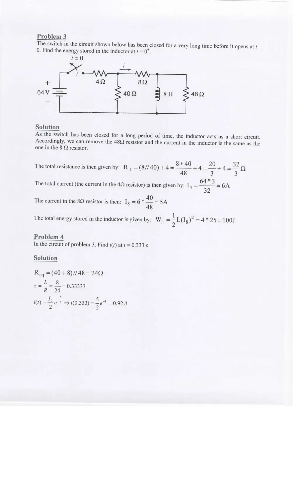
The switch in the circuit shown below has been closed for a very long time before it opens at ¢ =
0. Find the energy stored in the inductor at = 0".
480
Solution
As the switch has been closed for a long period of time, the inductor acts as a short circuit.
Accordingly, we can remove the 48Q resistor and the current in the inductor is the same as the
one in the 8 Q resistor.
8* 40 20 32
The total resistance is then given by: Ry =(8//40)+4= re +4= 5 +4= : Q
: an. . 64 *3
The total current (the current in the 4Q resistor) is then given by: I, = 39 =6A
. ne 40
The current in the 8Q resistor is then: Ig = 6 * a8 =5A
1
The total energy stored in the inductor is given by: W, =—L(I ) =4*25=100J
L 2 8
Problem 4
In the circuit of problem 3, Find i(s) at f= 0.333 s.
Solution
Reg =(40 +8)//48 = 240
c= 4-8 933333
R 24
“ay fi, en 5 4
i(t)= me * => i(0.333) = Se = 0.924
Problem 5
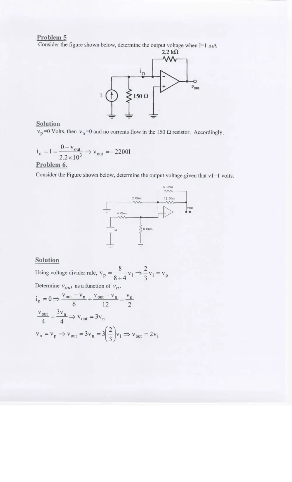
Consider the figure shown below, determine the output voltage when I=] mA
2.2k0
Solution
Yp =0 Volts, then v, =0 and no currents flow in the 150 Q resistor. Accordingly,
_ Oven
~ 2.2103
Problem 6.
Consider the Figure shown below, determine the output voltage given that v1=1 volts.
i, =I => Vou, =-22001
n
6 Ohm
2 Ohm 12 Ohm
WIN o——-VV-
a iS yout
= 4 0hm +
NWA
= 8 Ohm
Solution
. a 8 2
Using voltage divider rule, Yop —o a, I= al = “p
8+4 3
Determine V,,; as a function of v,,.
3 Vout’. Vout =v. Vv
in = 0 => out n ae out n = n
6 12 )
Vv 3Vv
out —s n => Vout = 3,
4 4
y)
Vn =Vp > Vout =3Vn -(2}y => Vout =2V,
Problem 7
For the circuit shown below, the switch has been in its position for a long period of time.
oe
3s
What is the value of the current in the inductor i, at t = 0°?
Solution
The inductor, and before the switch is open, acts as a short circuits.
20
pe
240 + (200//800)
200
°300+800—
ing
ip =ip
Problem 8
The figure shown below is equivalent to a single inductor having an equivalent inductance of 15
Henries. Determine L
Le
Solution
The 25 H inductor is in series with a parallel combination of 20H and 60 H inductors. The
inductance of the equivalent inductor is: 25+((60*20)/(60+20))=40 H. The 30 H inductor is in
parallel with a short circuit, which is equivalent to as short circuit. After making these
simplifications, we have
40 11
Lg =L, #10, De Sy ee
L,; 20 40 L 3L+40
Substituting, we obtain
i. - 40k +105 3LL,, +40L.. = 40L+30L +400
eq «4 9
3L +40
400 - 40L gq
~ 3Lgg —70
Problem 9
Find the Thevenin equivalent voltage seen between terminals ab if V1 = 3V and R1 = 10Q.
50 409 R1
¢\/\/\-9——$9—9 \V\V\9 \V\\0 a
ance
es
Vv
sov( * .
5A
v
e e ob
Solution
Let V2 be the node voltage to the left of the 5 Q resistor and V3 to the right. Using Nodal
. V3; V3; -—50
analysis, we have: V2 = 50 Volts and — + +5=0
20
Rearranging the above equation, we obtain
V3; +4V; —200+100=0=> 5V; =100 => V, =20 Volts
V3 — Vay = V; => Vep = V3 -V, =20-V,
Problem 10
The switch was open for a long time before it closes at t=0. Find the voltage across the capacitor
after t= It (one time constant after closing the switch) given that R = 10 kQ.
100 pA 0.4 wF
20 kO 5k 10kQ
¢ AWN ? WA- WW, 9
wv LY R $
o-
Solution
First, let us determine the initial voltage across the capacitor when the switch is open.
1. Convert the current source in parallel with the 20 KQ resistir to a voltage source of 2 V in
series with this resistor
2. Combine the two voltage sources into one source of 8 Volts
3. Use voltage divider rule to obtain the voltage across the 10 KQ resistor
8*10 80
10+5+20+R, 35+R,
When the switch is open, the capacitor will discharge through the 10 KQ resistor.
0 — 6 4
€ €
35+R, 35+R,
V,(t) =
Problem 11
The switch was closed for a long time. It opens at t=0. Find the total energy stored in the
capacitors at t=0, given that C = 11F.
9) 1) 2
1SkO x 20 kO
MA, AAA Ya
-
Cc = 40 kO
é
Solution
When the switch is closed for a very long period of time, both capacitors acts as open circuits
and the voltage across the 5uF and the capacitor C are the voltages across the 20 KQ and the
60KQ resistors, respectively.
* *
Vip =—15%40_ _15*40 _ gyi,
15+20+40 75
15*20 _ 15*20
15+20+40 75
=4 Volts
Vo =
Energy stored in the capacitors is given by
E= 5 (5810-4?) +(C¥10-* V8?) Joules
Problem 12
Assume in the following circuit L}=3 H, L2=2 H, L3=26H, and M=5H. Find the mesh equation
around i2.
on
Solution
. di,
3i5 +L, —+-
2 at
Ip =i, —13
di di d
3i2 +L; + -M— +1(i, -i,) +L, <(i, -i, +i.) =0
2 - (iz —i,) 27 2 1 +1,)
di di di
Ly — +(L, +L.)—2-(M+L,)—!-i, +4, =0
oa wa | 2) 1, +415
Problem 13
In the circuit shown below, find the output voltage Vo if V=2V V=1V assuming that all
operational amplifiers are ideal and operating in their linear region.
vt
10K
SK
5K
10K
Solution
Vv “UH
10K
SK
SK
10K
v
Voltage at node (a) is equal to V* = 2 Volts and the voltage at node b is equal to V=1 volts.
Therefore, the current in the 5K resistor (which is the same in the 10K and 20K resistors) is
given by:
Va Vp =5*10° *i>i=0.2mA
Voi — Va = 20*10° *0.2*107 = vo, =4+2=6 volts
Vp — Von =10*10° *0.2*10 = vo, =1-2=-1 volts
Vo = 2a —Vo,) =14 volts
Problem 14
In the circuit shown below, calculate the maximum power that can be dissipated by R, if
Vx=6V.
b Vx
©
+
S20
WAVAY
w
(2)
5
AVA,
Lo
12A
Solution
Maximum power transfer is obtained when the load is equal to Ry. Accordingly, we need to
determine the Thevenin equivalent
Ry, =(2+1)/34+3=4.50
Vth = 12 _ V30
V3q is the voltage across the 3Q resistor which is obtained by converting the current source
parallel to a resistor to a voltage source in series with the resistor, add the two voltage sources,
and use voltage divider rule.
_ (12—Vx)*3 _ 2-V,)
Van =
32 6 2
Vy =12-02=Va) _ 12+,
2 2
Maximum power transfer is given by:
Vin _ (12+V,)? _ (12+V,)?
4Ry, 4*4*4.5 4*18
P=
(18)?
For V, = 6 volts=> P= = 4.5 Watts
= 4*18