
EECE 312L Lab Report, Fall 2011
American University of Beirut · Circuits and Electronics Lab · 13 pages



Showing the first 10 of 13 pages. Download the PDF to see all of it.
More EECE 312L files
Show the text of this lab
American University of Beirut
ECE312 Lab
MyDAQ Assignment 3
Bilal Itani
20110****
Due on 23/12/2011
1. Description of the hardware setup:
Figure A-1: One diode clipping circuit
We use AO0 & AGND of the MyDAQ
from which we can get the input
voltage signal.
We use AI0+ & AI0- of the MyDAQ in
order to plot the output voltage
signal on the scope & measure the
values needed.
Figure A-2: One Zener clipping circuit
Figure A-3: Two diode clipping circuit
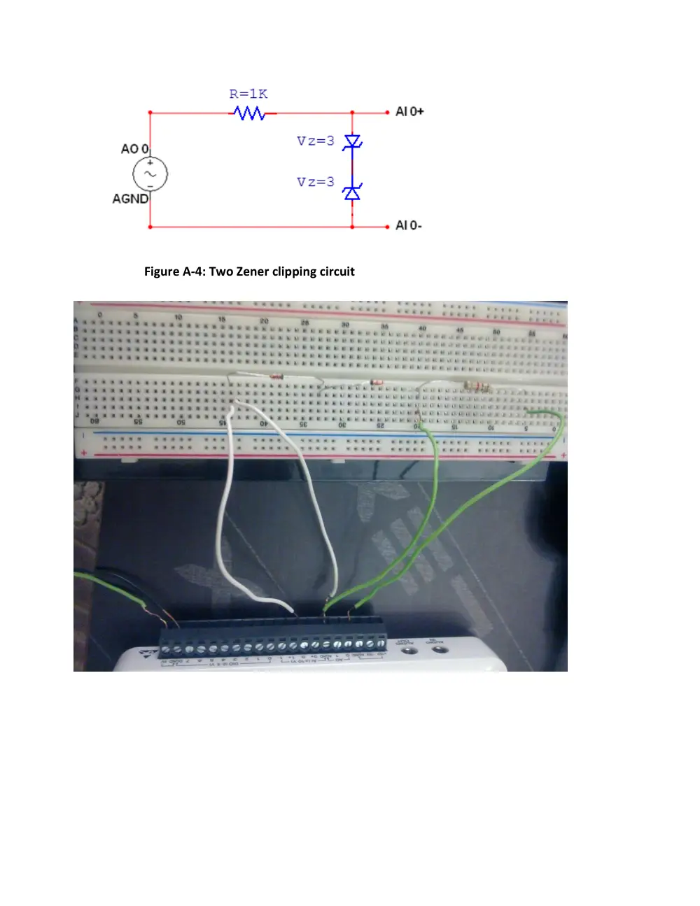
Figure A-4: Two Zener clipping circuit
Figure A-5: Diode clipping with DC source
Figure B-1: Voltage regulator used as DC source
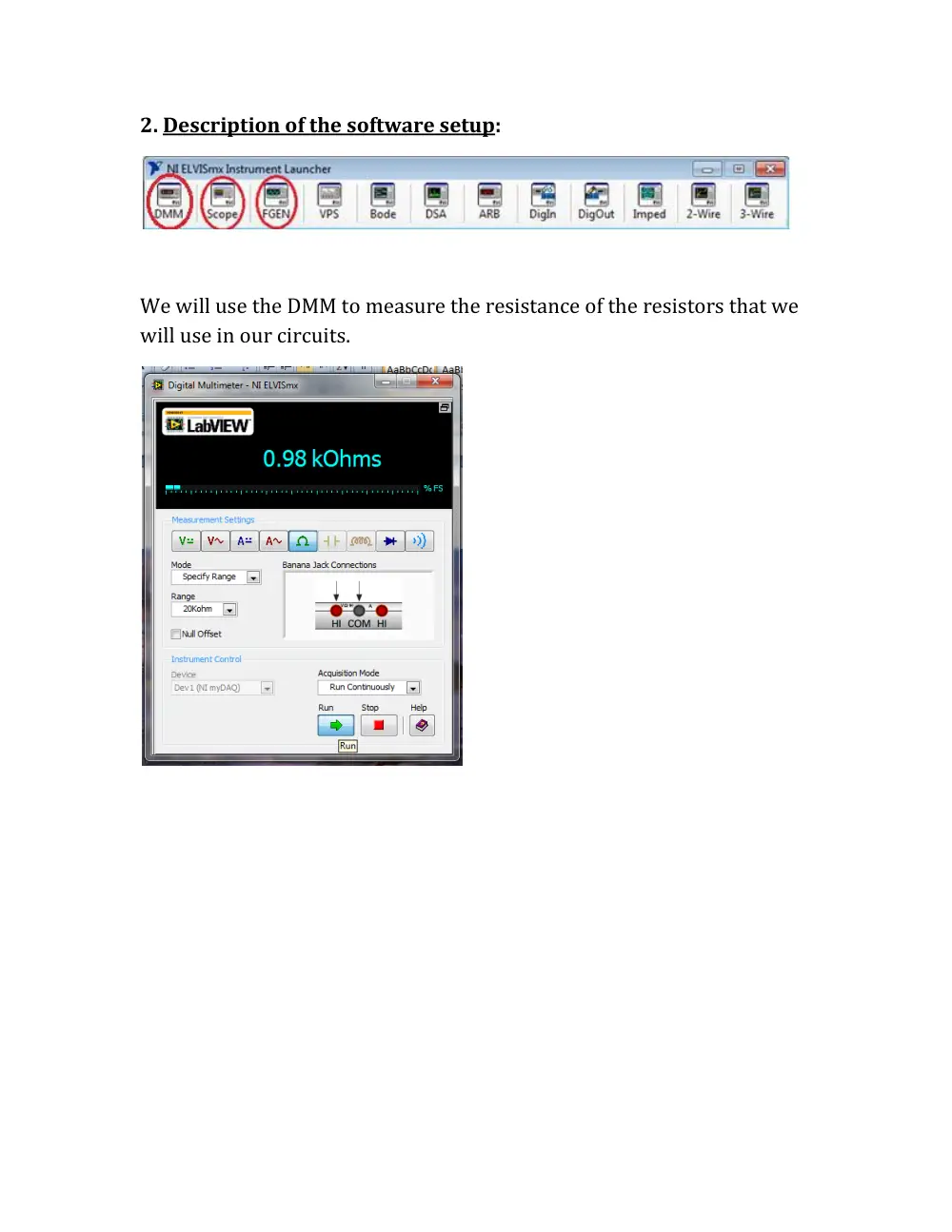
2. Description of the software setup:
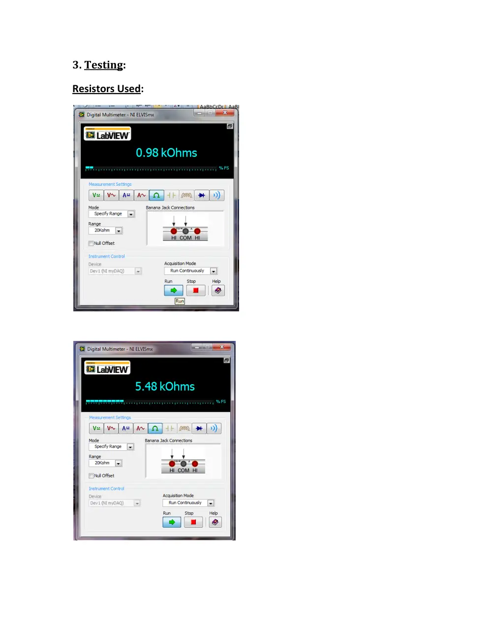
We will use the DMM to measure the resistance of the resistors that we
will use in our circuits.
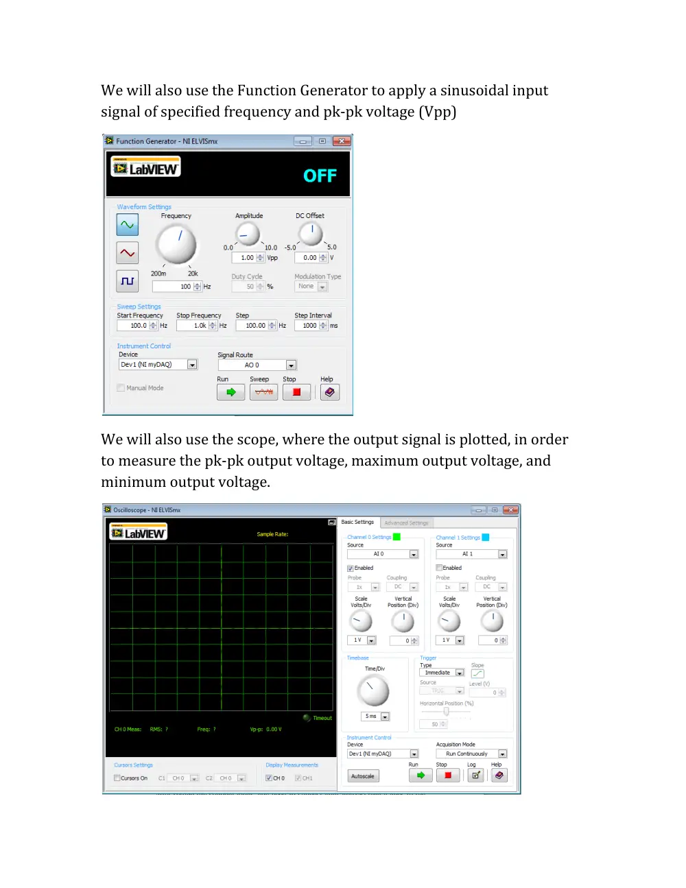
We will also use the Function Generator to apply a sinusoidal input
signal of specified frequency and pk-pk voltage (Vpp)
We will also use the scope, where the output signal is plotted, in order
to measure the pk-pk output voltage, maximum output voltage, and
minimum output voltage.
3. Testing:
Resistors Used:
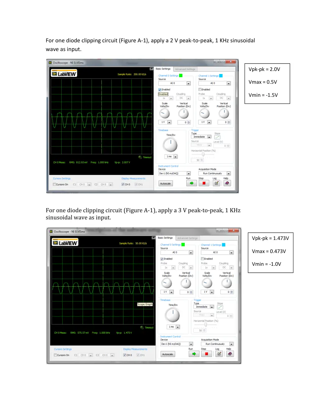
For one diode clipping circuit (Figure A-1), apply a 2 V peak-to-peak, 1 KHz sinusoidal
wave as input.
For one diode clipping circuit (Figure A-1), apply a 3 V peak-to-peak, 1 KHz
sinusoidal wave as input.
Vpk-pk = 2.0V
Vmax = 0.5V
Vmin = -1.5V
Vpk-pk = 1.473V
Vmax = 0.473V
Vmin = -1.0V
For one Zener clipping circuit (Figure A-2), apply a 3 V peak-to-peak, 1 KHz
sinusoidal wave as input.
For one Zener clipping circuit (Figure A-2), apply a 10 V peak-to-peak, 1 KHz
sinusoidal wave as input.
Vpk-pk = 3.36V
Vmax = 2.56V
Vmin = -0.8V
Vpk-pk = 2.192V
Vmax = 1.4V
Vmin = -0.792V
For two diode clipping circuit (Figure A-3), apply a 2 V peak-to-peak, 1 KHz
sinusoidal wave as input.
For two Zener clipping circuit (Figure A-4), apply a 10 V peak-to-peak, 1 KHz
sinusoidal wave as input.
Vpk-pk = 953.8mV
Vmax = 476.9mV
Vmin = -476.9mV
Vpk-pk = 6.693V
Vmax = 3.347V
Vmin = -3.347V
For diode clipping circuit with DC source (Figure A-5), apply a 10 V peak-to-peak, 1
KHz sinusoidal wave as input.
Vpk-pk = 8.211V
Vmax = 3.21V
Vmin = -5.0V