
EECE 320 Project, Spring 2008
American University of Beirut · Digital Systems Design · 60 pages

Showing the first 10 of 60 pages. Download the PDF to see all of it.
More EECE 320 files
Show the text of this project
10/19/26
331_22
1
Error Handling
ECE-331, Digital Design
Dr. Ron Hayne
Electrical and Computer Engineering
10/19/26
331_22
2
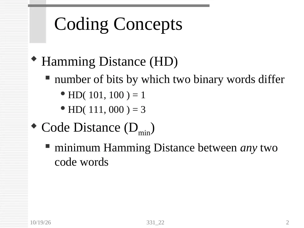
Coding Concepts
Hamming Distance (HD)
number of bits by which two binary words differ
HD( 101, 100 ) = 1
HD( 111, 000 ) = 3
Code Distance (Dmin)
minimum Hamming Distance between any two
code words
10/19/26
331_22
3
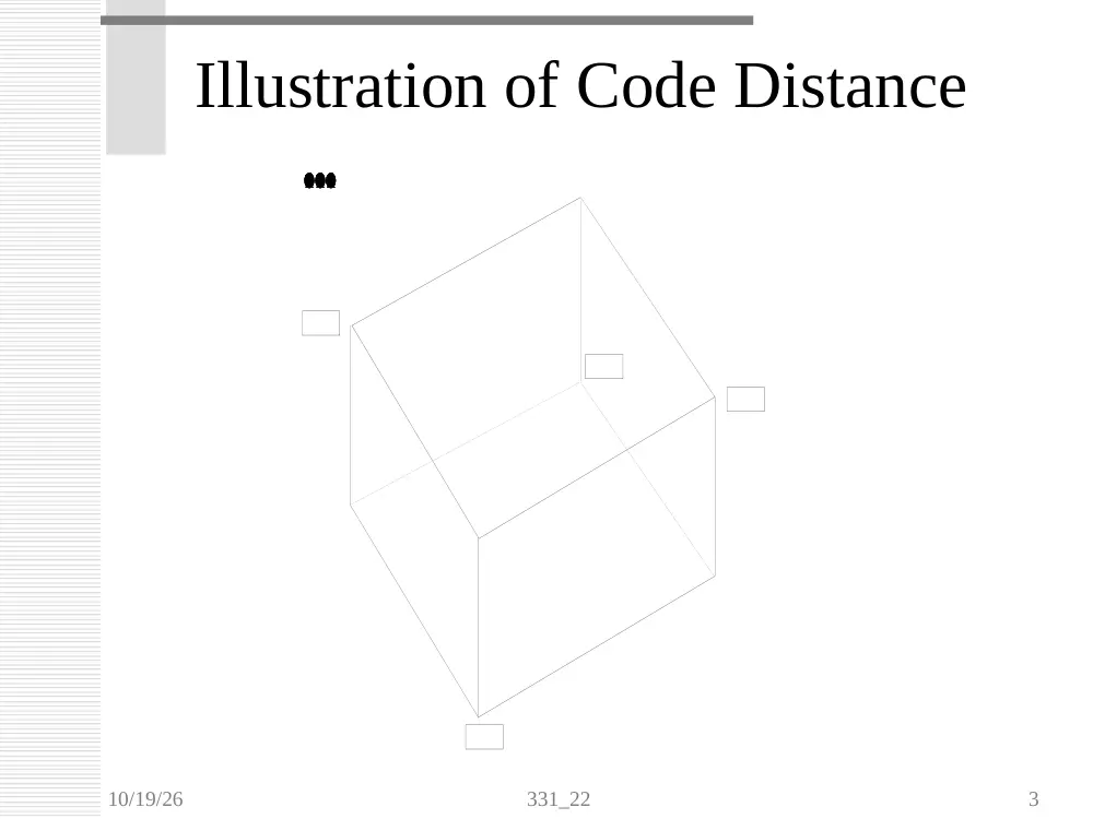
Illustration of Code Distance
000
001
101
100
111
110
011
010
10/19/26
331_22
4
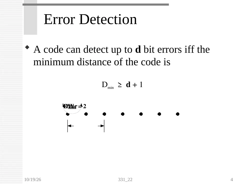
Error Detection
A code can detect up to d bit errors iff the
minimum distance of the code is
Dmin ≥ d + 1
CW
CW
CW
CW
error
error
Dmin = 2
10/19/26
331_22
5
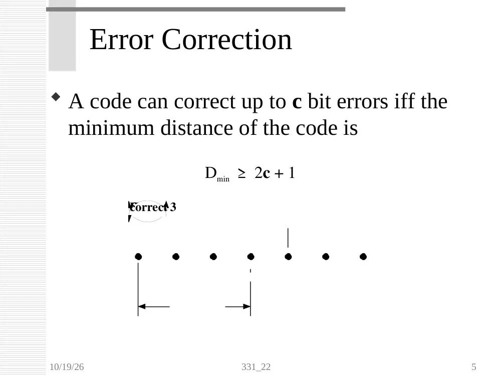
Error Correction
A code can correct up to c bit errors iff the
minimum distance of the code is
Dmin ≥ 2c + 1
CW
CW
CW
error
error
Dmin = 3
correct
10/19/26
331_22
6
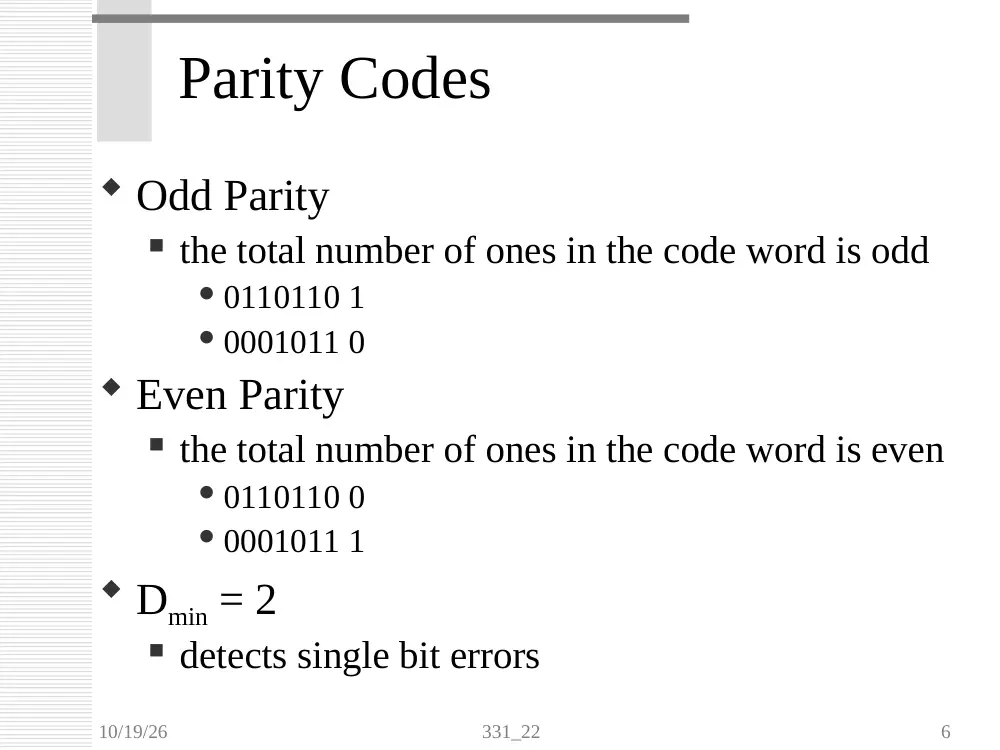
Parity Codes
Odd Parity
the total number of ones in the code word is odd
0110110 1
0001011 0
Even Parity
the total number of ones in the code word is even
0110110 0
0001011 1
Dmin = 2
detects single bit errors
10/19/26
331_22
7
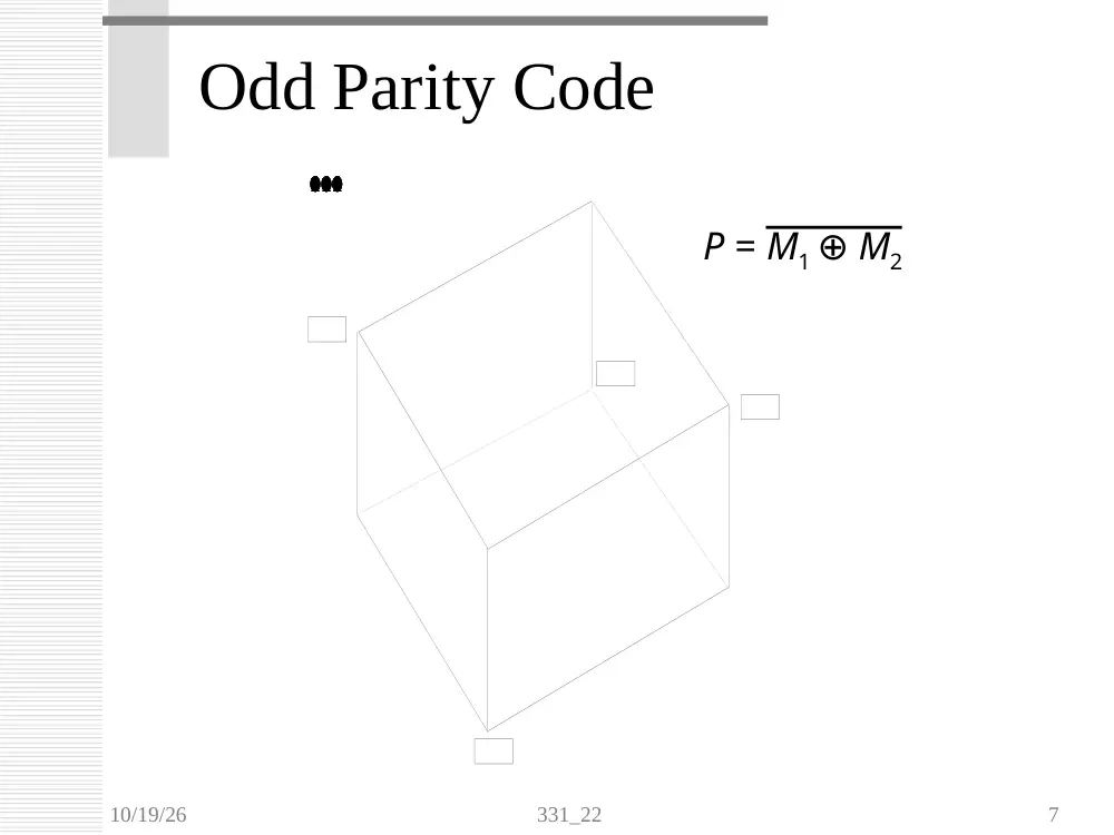
Odd Parity Code
000
001
101
100
111
110
011
010
P = M1 ⊕ M2
10/19/26
331_22
8
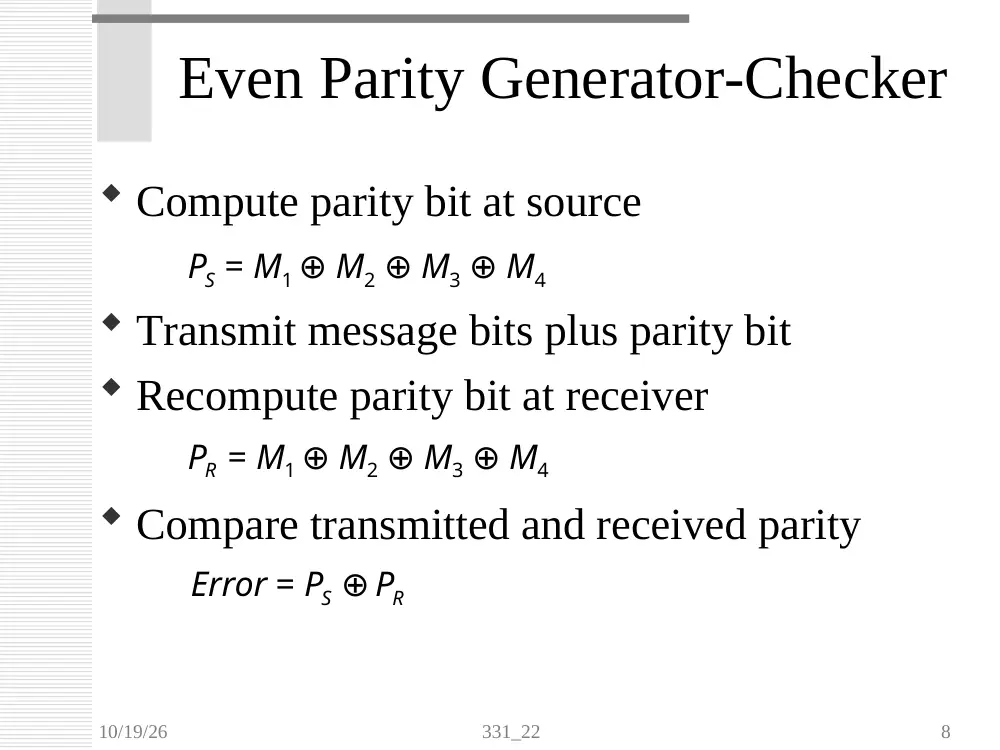
Compute parity bit at source
Transmit message bits plus parity bit
Recompute parity bit at receiver
Compare transmitted and received parity
Even Parity Generator-Checker
PS = M1 ⊕ M2 ⊕ M3 ⊕ M4
PR = M1 ⊕ M2 ⊕ M3 ⊕ M4
Error = PS ⊕ PR
10/19/26
331_22
9
Even Parity Generator-Checker
M1
M1
M2
M2
M3
M3
M4
M4
Source
Receiver
Channel
Error
PS
PR
10/19/26
331_22
10
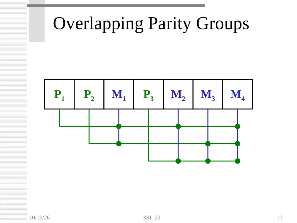
Overlapping Parity Groups
P1
P2
M1
P3
M2
M3
M4
10/19/26
331_22
11
Hamming Code
Overlapping Parity
m is number of message bits
p is number of parity bits
smallest integer that satisfies 2p m + p + 1
Example
m = 4, 23 4 + 3 + 1 => p = 3
Dmin = 3
detects double bit errors
corrects single bit errors
10/19/26
331_22
12
Hamming Code Block Diagram
Encoder
Channel
m
m+p
Corrector
Checker
m+p
Decoder
m
m
p
2p
m+p
Source
Receiver
10/19/26
331_22
13
Hamming Parity Generation
Bit Position
1
001
2
010
3
011
4
100
5
101
6
110
7
111
Designation
P1
P2
M1
P3
M2
M3
M4
10/19/26
331_22
14
Hamming Parity Generation
Bit Position
1
001
2
010
3
011
4
100
5
101
6
110
7
111
Designation
P1
P2
M1
P3
M2
M3
M4
P1 = M1 ⊕ M2 ⊕ M4
10/19/26
331_22
15
Hamming Parity Generation
Bit Position
1
001
2
010
3
011
4
100
5
101
6
110
7
111
Designation
P1
P2
M1
P3
M2
M3
M4
P1 = M1 ⊕ M2 ⊕ M4
P2 = M1 ⊕ M3 ⊕ M4
10/19/26
331_22
16
Hamming Parity Generation
Bit Position
1
001
2
010
3
011
4
100
5
101
6
110
7
111
Designation
P1
P2
M1
P3
M2
M3
M4
P1 = M1 ⊕ M2 ⊕ M4
P2 = M1 ⊕ M3 ⊕ M4
P3 = M2 ⊕ M3 ⊕ M4
10/19/26
331_22
17
Hamming Parity Checker
Bit Position
1
001
2
010
3
011
4
100
5
101
6
110
7
111
Designation
P1
P2
M1
P3
M2
M3
M4
C1 = P1 ⊕ M1 ⊕ M2 ⊕ M4
C2 = P2 ⊕ M1 ⊕ M3 ⊕ M4
C3 = P3 ⊕ M2 ⊕ M3 ⊕ M4
Syndrome C3C2C1 indicates bit position in error
10/19/26
331_22
18
Corrected Data Bits
Bit Position
1
001
2
010
3
011
4
100
5
101
6
110
7
111
Designation
P1
P2
M1
P3
M2
M3
M4
10/19/26
331_22
19
Example
Determine the Hamming Code for the
message 10101 using even parity
m = 5, 24 5 + 4 + 1 => p = 4
Bit
Position
1
0001
2
0010
3
0011
4
0100
5
0101
6
0110
7
0111
8
1000
9
1001
Desig.
P1
P2
M1
P3
M2
M3
M4
P4
M5
10/19/26
331_22
20
Example
Bit
Position
1
0001
2
0010
3
0011
4
0100
5
0101
6
0110
7
0111
8
1000
9
1001
Desig.
P1
P2
M1
P3
M2
M3
M4
P4
M5
Message
1
0
1
0
1
Parity
10/19/26
331_22
21
Example
Bit
Position
1
0001
2
0010
3
0011
4
0100
5
0101
6
0110
7
0111
8
1000
9
1001
Desig.
P1
P2
M1
P3
M2
M3
M4
P4
M5
Message
1
0
1
0
1
Parity
0
P1 = M1 ⊕ M2 ⊕ M4 ⊕ M5
=1⊕0 ⊕0 ⊕1
= 0
10/19/26
331_22
22
Example
Bit
Position
1
0001
2
0010
3
0011
4
0100
5
0101
6
0110
7
0111
8
1000
9
1001
Desig.
P1
P2
M1
P3
M2
M3
M4
P4
M5
Message
1
0
1
0
1
Parity
0
0
P2 = M1 ⊕ M3 ⊕ M4
=1⊕1⊕ 0
= 0
10/19/26
331_22
23
Example
Bit
Position
1
0001
2
0010
3
0011
4
0100
5
0101
6
0110
7
0111
8
1000
9
1001
Desig.
P1
P2
M1
P3
M2
M3
M4
P4
M5
Message
1
0
1
0
1
Parity
0
0
1
P3 = M2 ⊕ M3 ⊕ M4
= 0⊕1⊕ 0
=1
10/19/26
331_22
24
Example
Bit
Position
1
0001
2
0010
3
0011
4
0100
5
0101
6
0110
7
0111
8
1000
9
1001
Desig.
P1
P2
M1
P3
M2
M3
M4
P4
M5
Message
1
0
1
0
1
Parity
0
0
1
1
P4 = M5
=1
10/19/26
331_22
25
Example
Bit
Position
1
0001
2
0010
3
0011
4
0100
5
0101
6
0110
7
0111
8
1000
9
1001
Desig.
P1
P2
M1
P3
M2
M3
M4
P4
M5
Message
1
0
1
0
1
Parity
0
0
1
1
Hamming Code = 001101011
10/19/26
331_22
26
Example Continued
The following Hamming coded message was
received under even parity: 001101111
Determine the correct message bits
Bit
Position
1
0001
2
0010
3
0011
4
0100
5
0101
6
0110
7
0111
8
1000
9
1001
Desig.
P1
P2
M1
P3
M2
M3
M4
P4
M5
Message
1
0
1
1
1
Parity
0
0
1
1
10/19/26
331_22
27
Example Continued
Bit
Position
1
0001
2
0010
3
0011
4
0100
5
0101
6
0110
7
0111
8
1000
9
1001
Desig.
P1
P2
M1
P3
M2
M3
M4
P4
M5
Message
1
0
1
1
1
Parity
0
0
1
1
C1 = P1 ⊕ M1 ⊕ M2 ⊕ M4 ⊕ M5
= 0⊕1⊕ 0⊕1⊕1
=1
10/19/26
331_22
28
Example Continued
Bit
Position
1
0001
2
0010
3
0011
4
0100
5
0101
6
0110
7
0111
8
1000
9
1001
Desig.
P1
P2
M1
P3
M2
M3
M4
P4
M5
Message
1
0
1
1
1
Parity
0
0
1
1
C2 = P2 ⊕ M1 ⊕ M3 ⊕ M4
= 0 ⊕1⊕1⊕1
=1
10/19/26
331_22
29
Example Continued
Bit
Position
1
0001
2
0010
3
0011
4
0100
5
0101
6
0110
7
0111
8
1000
9
1001
Desig.
P1
P2
M1
P3
M2
M3
M4
P4
M5
Message
1
0
1
1
1
Parity
0
0
1
1
C3 = P3 ⊕ M2 ⊕ M3 ⊕ M4
=1⊕0 ⊕1⊕1
=1
10/19/26
331_22
30
Example Continued
Bit
Position
1
0001
2
0010
3
0011
4
0100
5
0101
6
0110
7
0111
8
1000
9
1001
Desig.
P1
P2
M1
P3
M2
M3
M4
P4
M5
Message
1
0
1
1
1
Parity
0
0
1
1
C4 = P4 ⊕ M5
=1⊕1
= 0
10/19/26
331_22
31
Example Continued
Bit
Position
1
0001
2
0010
3
0011
4
0100
5
0101
6
0110
7
0111
8
1000
9
1001
Desig.
P1
P2
M1
P3
M2
M3
M4
P4
M5
Message
1
0
1
1
1
Parity
0
0
1
1
Syndrome C4C3C2C1 = 0111 bit position 7 in error
Corrected Data= M1M2M3M 4M5
=10101
10/19/26
331_22
32
Summary
Even/Odd Parity
Error Detection
Hamming Code
Overlapping Parity
Error Correction
American University
Of Beirut
EECE 320
Combinational Circuit Project #1
December 17, 2007
XXX
XXX
XXX
Page 1 of 9
I.
A.
Codeword
Information
Bits
Parity Bits
1
0000
2
3
4
5
6
7
8
0001
9
10
11
12
13
1100
0011
14
1101
0100
15
1110
1000
16
1111
1111
Table 1.
B.
To prove that the minimum distance of a Hamming code is 4 we need to show that for a 1 bit
change, a 2 bit change, and a 3 bit change that the resulting code word is a non-code word, while
if we change 4 bits then we will receive a code word.
If 1 bit is changed in position j then at least one of the parity groups will change in parity.
Since one of the groups has an incorrect parity then the code word is a non-code word.
If 2 bits are changed in positions j and k then the parity group that contains both these bits
will have the same parity. However, since j and k are different they differ in at least one bit,
meaning that their corresponding groups will change in parity. This means that the codeword is a
non-code word.
If 3 bits are changed in positions j, k and l then the parity of the group that contains these
three bits (if any) will have its parity changed. The parity groups which contain two of these
positions will have the same parity while the parity groups that have one of these positions will
have a changed parity. All of this means that we have a non-code word.
It is left to say that if 4 bits are changed then we will have a code word. This is so since
according to our table of part A, we can see that the number of bits changed from codeword to
codeword, including the parity bits, is four bits.
Page 2 of 9
II.
U 2
1
13
9
10
11
12
2
3
4
5
8
6
I [7]
I [6]
I [5]
I [4]
E nable
N U LL
I [3]
I [2]
I [1]
I [0]
E V E N
O D D
I [6]A
O 6
2
3
1
U 7A
7406
1
2
U 2
1
13
9
10
11
12
2
3
4
5
8
6
I [7]
I [6]
I [5]
I [4]
E nable
N U LL
N U LL
N U LL
N U LL
N U LL
E V E N
O D D
1
2
E nable
1
2
1
2
U 6A
7406
1
2
I [0:7]
I [0]A
O 0
2
3
1
I [4]A
O 4
2
3
1
1
2
I [1]A
O 1
2
3
1
I [5]A
O 5
2
3
1
1
2
I [3]A
O 3
2
3
1
U 4A
7406
1
2
U 2
1
13
9
10
11
12
2
3
4
5
8
6
I [7]
I [5]
I [3]
I [1]
E nable
N U LL
N U LL
N U LL
N U LL
N U LL
E V E N
O D D
1
2
1
2
S y ndrom e V ec tor
1
2
E R R O R
1
2
I [7]A
O 7
2
3
1
O [0:7]
I [2]A
O 2
2
3
1
U 5A
7406
1
2
U 9A
7427
1
2
13
12
U 2
1
13
9
10
11
12
2
3
4
5
8
6
I [7]
I [6]
I [3]
I [2]
E nable
N U LL
N U LL
N U LL
N U LL
N U LL
E V E N
O D D
U 8
7443A
15
14
13
12
1
2
3
4
5
6
7
9
10
11
E N A B LE
S Y N 1
S Y N 2
S Y N 3
Y 0
Y 1
Y 2
Y 3
Y 4
Y 5
Y 6
Y 7
Y 8
Y 9
Circuit 1.
This is the circuit for our VHDL code that we’ve written. We have used here 4 encoders to check
the parity of the parity groups. The four parity groups are {1,3,5,7}, {2,3,6,7}, {4,5,6,7} and
{0,1,2,3,4,5,6,7}. Now the bits are sorted in the code word according to the following
distribution:
7
6
5
3
4
2
1
0
So all the parity groups are based on this numbering and not on:
7
6
5
4
3
2
1
0
Page 3 of 9
Now once we find the parity of all these groups we have to correct the code, if there is any error
of course. To correct the code we input all these parity groups into a decoder. The decoder has
three inputs, SYN1, SYN2 and SYN3. The fourth input is an ENABLE input which is the SYN4
parity group.
According to the requirements of this project we are asked to fix the code if there is a one bit
error and to only indicate if there is an error if there are more than one bit errors. So if the parity
of SYN4 is odd, then we either have a one bit error or a three bit error. In either case our code
corrects it to a codeword for the one bit error and a non-code word for the three bit error.
Now once the syndrome vector is input into the decoder, we find which bit is wrong. It should be
noted that the decoder is only used when SYN4 = ‘1’ indicating an odd number of 1’s in the
code. So when there is an error the bit to be flipped will make one of the outputs of the decoder
equal to ‘1’. This ‘1’ is inverted twice which means that it stays ‘1’.
Once the preceding step is finished the outputs of the decoder are input into separate XOR gates.
If the inputs to the XOR gates from the decoder’s outputs are ‘0’ then the output is equal to the
other input of the XOR gate namely, I [0:7]. The input from the decoder which is equal to ‘1’
simply flips the other input from I [0:7]. In this way we are able to flip the incorrect bit so as to
correct the codeword.
Finally the circuit indicates if there is an error or not by the use of a three input NOR gate
followed by an inverter. If one of the bits of the syndrome vector is ‘1’ then there will be an error
and this is the basis for this part of the circuit. The syndrome vector output is simply a three bit
vector where each bit is a parity group’s parity.
The Main Code for the project
library ieee;
use ieee.std_logic_1164.all;
entity Hammering is
port (enable: in std_logic;
I: in std_logic_vector(8 downto 1);
O: out std_logic_vector(4 downto 1);
syndrome: out std_logic_vector(3 downto 1);
error: out std_logic);
end Hammering;
architecture Hammering_arch of Hammering is
function parity(X: std_logic_vector) return std_logic is
variable count: integer:=0;
begin
for i in X'range loop
if X(i)='1' then count:=count+1; end if;
end loop;
Page 4 of 9
if (count mod 2)=0 then return '0';
else return '1'; end if;
end parity;
signal syn1: std_logic_vector(4 downto 1);
signal syn2: std_logic_vector(4 downto 1);
signal syn3: std_logic_vector(4 downto 1);
signal syn4: std_logic_vector(8 downto 1);
signal syntemp: std_logic_vector(3 downto 1);
signal Otemp: std_logic_vector(4 downto 1);
signal Otemp2: std_logic_vector(4 downto 1);
signal Otemp3: std_logic_vector(4 downto 1);
signal synparity: std_logic;
begin
syn1(1)<=I(2);
syn1(2)<=I(5);
syn1(3)<=I(6);
syn1(4)<=I(8);
syn2(1)<=I(3);
syn2(2)<=I(5);
syn2(3)<=I(7);
syn2(4)<=I(8);
syn3(1)<=I(4);
syn3(2)<=I(6);
syn3(3)<=I(7);
syn3(4)<=I(8);
syn4<=I;
syntemp(1)<=parity(syn1);
syntemp(2)<=parity(syn2);
syntemp(3)<=parity(syn3);
synparity<=parity(syn4);
Otemp2(4)<=I(8);
Otemp2(3)<=I(7);
Otemp2(2)<=I(6);
Otemp2(1)<=I(5);
with syntemp select Otemp(4)<=
not I(8) when "111",
I(8) when others;
Page 5 of 9
with syntemp select Otemp(3)<=
not I(7) when "110",
I(7) when others;
with syntemp select Otemp(2)<=
not I(6) when "101",
I(6) when others;
with syntemp select Otemp(1)<=
not I(5) when "011",
I(5) when others;
error<='0' when syntemp="000" else '1';
Otemp3<=Otemp when synparity='1' else Otemp2;
syndrome<=syntemp when enable='1' else "000";
O<=Otemp3 when enable='1' else "0000";
end Hammering_arch;
Explanation of the Main Code
Now the design of our project is based on a structural design. We have used one function
in this design so as to check the parity of the parity groups. This function has 9 signals. At first
we define the parity groups (syn1, syn2, syn3, syn4) by assigning their bits according to the
following bit distribution:
7
6
5
3
4
2
1
0
8
7
6
5
4
3
2
1
Since syn1 should get {1,3,5,7} it gets {2,5,6,8}. The same goes for the other parity
groups. Syntemp is the temporary syndrome vector, where each bit represents the parity of the
parity groups excluding syn4. Synparity computes the parity of the fourth parity group, and will
be used as an inner enable for the circuit.
We have assigned the signal Otemp2 to the last four bits, information bits, of the input
codeword. Otemp is another signal that we have used where its bits are the information bits,
however the information bits in this signal may be flipped according to the syndrome vector. As
you can see we have placed conditions for each of the bits so that Otemp will take the value of
the input codeword when that bit is not a bit in error, and Otemp will take the flipped value of
the input codeword when that bit is a bit in error.
The error output gets equal to ‘0’ when syntemp is “000” otherwise it is ‘1’. Now another
signal Otemp3 is used. The function of this signal is to take the value of Otemp2 when the syn4
parity group is equal to ‘0’ and it is to take the value of Otemp when syn4 is equal to ‘1’. This
means that if there is no error or a 2-bit error or a 4-bit error in the code then the value of
Otemp3 is the original codeword which is saved in the signal Otemp2.
Page 6 of 9
The output O gets the value of Otemp3 when the enable input is ‘1’ and it gets the value
of “0000” when enable is ‘0’. Finally syndrome which is the syndrome vector, gets the value of
syntemp when enable = ‘1’ otherwise it gets equal to “000”.
To run this code you need suitable test benches. We have written those test benches and
have supplied them to you. They test the code to the maximum extent proving that our work is
correct. They contain no errors, 1-bit errors, 2-bit errors, 3-bit errors and 4-bit errors. The wave
forms of these test benches are shown below.
The files that constitute our project (and their purpose) are the following:
Hammering: This is the main code for the design of our circuit.
Hammering_tb: This is the test bench which tests Hammering, and this test bench
contains the 16 possible code words of the table in part I. These code words, of course,
have no errors in them.
Hammering_1_error: This is the test bench which contains three different code words
which contain one error each. (The code is corrected to a correct code word)
Hammering_2_error: This is the test bench which contains three different code words
which contain two errors each. (The code is not corrected)
Hammering_3_error: This is the test bench which contains three different code words
which contain three errors each. (The code is corrected to a non-code word)
Hammering_4_error: This is the test bench which contains three different code words
which contain four errors each. (The code is not corrected)
No error Test Bench
This waveform is the test bench of the 16 possible code words. As you can see the output is equal to
the original information bits since there are no errors.
One bit error Test Bench
Page 7 of 9
This waveform shows that since there is an error, and since it is a 1-bit error, we can see that the
output consists of a bit that has been flipped due to the presence of an error. This bit has been
flipped since the fourth parity group SYN4 is equal to ‘1’.
Two bit error Test Bench
In this waveform we can see that although the syndrome vector indicates that there is an error and the
error output indicates an error too, the output of the circuit is just like the input information bits. This
is all because of the fact that the fourth parity group SYN4 is equal to ‘0’ which means that the circuit
will not fix the code word.
Three bit error Test Bench
Page 8 of 9
This waveform acts in the same manner as the one bit error, however this is the waveform of a three
bit error. Since the fourth parity group is equal to ‘1’ the codeword is fixed, however it is corrected to
a non-code word.
Four bit error Test Bench
This waveform has its fourth parity group’s parity always equal to ‘0’ so the code word is never
corrected, and the output is equal to the original information bits.
Page 9 of 9
library ieee;
use ieee.std_logic_1164.all;
entity Hammer is
port (enable: in std_logic;
I: in std_logic_vector(8 downto 1);
O: out std_logic_vector(4 downto 1);
syndrome1: out std_logic_vector(3 downto 1);
syndrome2: out std_logic_vector(3 downto 1);
error: out std_logic);
end Hammer;
architecture Hammer_arch of Hammer is
function parity(X: std_logic_vector) return std_logic is
variable count: integer:=0;
begin
for i in 1 to 4 loop
if X(i)='1' then count:=count+1; end if;
end loop;
if (count mod 2)=0 then return '0';
else return '1'; end if;
end parity;
function parity2(X: std_logic_vector) return std_logic is
variable count: integer:=0;
begin
for i in 1 to 8 loop
if X(i)='1' then count:=count+1; end if;
end loop;
if (count mod 2)=0 then return '0';
else return '1'; end if;
end parity2;
function CONV_INTEGER (X: STD_LOGIC_VECTOR) return INTEGER is
variable RESULT: INTEGER;
begin
RESULT :=0;
for i in X'range loop
RESULT := RESULT*2;
case X(i) is
when '0'|'L' => null;
when '1'|'H' => RESULT :=RESULT +1;
when others => null;
end case;
end loop;
if (RESULT=0) then return 999; end if;
if (RESULT=1) then return RESULT+1; end if;
if (RESULT=2) then return RESULT+1; end if;
if (RESULT=3) then return RESULT+2; end if;
if (RESULT=4) then return RESULT; end if;
if (RESULT=5) then return RESULT+1; end if;
if (RESULT=6) then return RESULT+1; end if;
if (RESULT=7) then return RESULT+1; end if;
if (RESULT=8) then return 1; end if;
if (RESULT=9) then return 2; end if;
if (RESULT=10) then return 3; end if;
if (RESULT=11) then return 5; end if;
if (RESULT=12) then return 4; end if;
if (RESULT=13) then return 6; end if;
if (RESULT=14) then return 7; end if;
if (RESULT=15) then return 8; end if;
end CONV_INTEGER;
signal syn1: std_logic_vector(4 downto 1);
signal syn2: std_logic_vector(4 downto 1);
signal syn3: std_logic_vector(4 downto 1);
signal syn4: std_logic_vector(8 downto 1);
signal synparity2: std_logic_vector(4 downto 1);
signal Itemp: std_logic_vector(8 downto 1);
signal atemp: integer;
signal tempnot: std_logic;
signal Otemp: std_logic_vector(8 downto 1);
begin
process (I,syn1,syn2,syn3,syn4,synparity2,Itemp,enable,tempnot)
variable a: integer;
variable count: integer;
begin
if (enable='0') then
O<="0000"; syndrome1<="000";
syndrome2<="000";error<='0';
else
error<='0';
Itemp<=I;
count:=0;
for j in 1 to 4 loop
syn1(1)<=Itemp(2);
syn1(2)<=Itemp(5);
syn1(3)<=Itemp(6);
syn1(4)<=Itemp(8);
syn2(1)<=Itemp(3);
syn2(2)<=Itemp(5);
syn2(3)<=Itemp(7);
syn2(4)<=Itemp(8);
syn3(1)<=Itemp(4);
syn3(2)<=Itemp(6);
syn3(3)<=Itemp(7);
syn3(4)<=Itemp(8);
syn4<=Itemp;
syndrome1(1)<=parity(syn1);
syndrome1(2)<=parity(syn2);
syndrome1(3)<=parity(syn3);
if(count=1) then
syndrome2(1)<=parity(syn1);
syndrome2(2)<=parity(syn2);
syndrome2(3)<=parity(syn3);
end if;
count:=count+1;
synparity2(1)<=parity(syn1);
synparity2(2)<=parity(syn2);
synparity2(3)<=parity(syn3);
synparity2(4)<=parity2(syn4);
a:=CONV_INTEGER(synparity2);
atemp<=a;
if (a=999) then
error<='0'; end if;
if(a/=999) then
tempnot<=(not Itemp(a));
Itemp(a)<=tempnot;
error<='1';
end if;
end loop;
O(4)<=Itemp(8);
O(3)<=Itemp(7);
O(2)<=Itemp(6);
O(1)<=Itemp(5);
Otemp(1)<=Itemp(1);
Otemp(2)<=Itemp(2);
Otemp(3)<=Itemp(3);
Otemp(4)<=Itemp(4);
Otemp(5)<=Itemp(5);
Otemp(6)<=Itemp(6);
Otemp(7)<=Itemp(7);
Otemp(8)<=Itemp(8);
end if;
end process;
end Hammer_arch;
library ieee;
use ieee.std_logic_1164.all;
entity Hammer_tb_good is
end Hammer_tb_good;
architecture Hammer_tb_good_arch of Hammer_tb_good is
component Hammer port (enable: in std_logic;
I: in std_logic_vector(8 downto 1);
O: out std_logic_vector(4 downto 1);
syndrome1: out std_logic_vector(3 downto 1);
syndrome2: out std_logic_vector(3 downto 1);
error: out std_logic);
end component;
signal I: STD_LOGIC_VECTOR(8 downto 1):="00000000";
signal enable: std_logic:='1';
signal O: std_logic_vector(4 downto 1);
signal syndrome1: std_logic_vector(3 downto 1);
signal syndrome2: std_logic_vector(3 downto 1);
signal error: std_logic;
begin
U1: Hammer port map (enable=>enable,I=>I,O=>O,
syndrome1=>syndrome1,syndrome2=>syndrome2,error=>error );
U2:process
begin
I<="00000000"; wait for 10 ns;
I<="00010111"; wait for 10 ns;
I<="00101011"; wait for 10 ns;
I<="00111100"; wait for 10 ns;
I<="01001101"; wait for 10 ns;
I<="01011010"; wait for 10 ns;
I<="01100110"; wait for 10 ns;
I<="01110001"; wait for 10 ns;
I<="10001110"; wait for 10 ns;
I<="10011001"; wait for 10 ns;
I<="10100101"; wait for 10 ns;
I<="10110010"; wait for 10 ns;
I<="11000011"; wait for 10 ns;
I<="11010100"; wait for 10 ns;
I<="11101000"; wait for 10 ns;
I<="11111111"; wait for 10 ns;
end process;
end Hammer_tb_good_arch;
American University
Of Beirut
EECE 320
Combinational Circuit Project #1
December 17, 2007
XXX
XXX
XXX
I.
A.
Codeword
Information
Bits
Parity Bits
1
0000
2
3
4
5
6
7
8
0001
9
10
11
12
13
1100
0011
14
1101
0100
15
1110
1000
16
1111
1111
B.
To prove that the minimum distance of a Hamming code is 4 we need to show that for a 1 bit
change, a 2 bit change, and a 3 bit change that the resulting code word is a non-code word, while
if we change 4 bits then we will receive a code word.
If 1 bit is changed in position j then at least one of the parity groups will change in parity.
Since one of the groups has an incorrect parity then the code word is a non-code word.
If 2 bits are changed in positions j and k then the parity group that contains both these bits
will have the same parity. However, since j and k are different they differ in at least one bit,
meaning that their corresponding groups will change in parity. This means that the codeword is a
non-code word.
If 3 bits are changed in positions j, k and l then the parity of the group that contains these
three bits (if any) will have its parity changed. The parity groups which contain two of these
positions will have the same parity while the parity groups that have one of these positions will
have a changed parity. All of this means that we have a non-code word.
It is left to say that if 4 bits are changed then we will have a code word. This is so since
according to our table of part A, we can see that the number of bits changed from codeword to
codeword, including the parity bits, is four bits.
II.
U 2
1
13
9
10
11
12
2
3
4
5
8
6
I [7]
I [6]
I [5]
I [4]
E nable
N U LL
I [3]
I [2]
I [1]
I [0]
E V E N
O D D
I [6]A
O 6
2
3
1
U 7A
7406
1
2
U 2
1
13
9
10
11
12
2
3
4
5
8
6
I [7]
I [6]
I [5]
I [4]
E nable
N U LL
N U LL
N U LL
N U LL
N U LL
E V E N
O D D
1
2
E nable
1
2
1
2
U 6A
7406
1
2
I [0:7]
I [0]A
O 0
2
3
1
I [4]A
O 4
2
3
1
1
2
I [1]A
O 1
2
3
1
I [5]A
O 5
2
3
1
1
2
I [3]A
O 3
2
3
1
U 4A
7406
1
2
U 2
1
13
9
10
11
12
2
3
4
5
8
6
I [7]
I [5]
I [3]
I [1]
E nable
N U LL
N U LL
N U LL
N U LL
N U LL
E V E N
O D D
1
2
1
2
S y ndrom e V ec tor
1
2
E R R O R
1
2
I [7]A
O 7
2
3
1
O [0:7]
I [2]A
O 2
2
3
1
U 5A
7406
1
2
U 9A
7427
1
2
13
12
U 2
1
13
9
10
11
12
2
3
4
5
8
6
I [7]
I [6]
I [3]
I [2]
E nable
N U LL
N U LL
N U LL
N U LL
N U LL
E V E N
O D D
U 8
7443A
15
14
13
12
1
2
3
4
5
6
7
9
10
11
E N A B LE
S Y N 1
S Y N 2
S Y N 3
Y 0
Y 1
Y 2
Y 3
Y 4
Y 5
Y 6
Y 7
Y 8
Y 9
This is the circuit for our VHDL code that we’ve written. We have used here 4 encoders to check
the parity of the parity groups. The four parity groups are {1,3,5,7}, {2,3,6,7}, {4,5,6,7} and
{0,1,2,3,4,5,6,7}. Now the bits are sorted in the code word according to the following
distribution:
7
6
5
3
4
2
1
0
So all the parity groups are based on this numbering and not on:
7
6
5
4
3
2
1
0
Now once we find the parity of all these groups we have to correct the code, if there is any error
of course. To correct the code we input all these parity groups into a decoder. The decoder has
three inputs, SYN1, SYN2 and SYN3. The fourth input is an ENABLE input which is the SYN4
parity group.
According to the requirements of this project we are asked to fix the code if there is a one bit
error and to only indicate if there is an error if there are more than one bit errors. So if the parity
of SYN4 is odd, then we either have a one bit error or a three bit error. In either case our code
corrects it to a codeword for the one bit error and a non-code word for the three bit error.
Now once the syndrome vector is input into the decoder, we find which bit is wrong. It should be
noted that the decoder is only used when SYN4 = ‘1’ indicating an odd number of 1’s in the
code. So when there is an error the bit to be flipped will make one of the outputs of the decoder
equal to ‘1’. This ‘1’ is inverted twice which means that it stays ‘1’.
Once the preceding step is finished the outputs of the decoder are input into separate XOR gates.
If the inputs to the XOR gates from the decoder’s outputs are ‘0’ then the output is equal to the
other input of the XOR gate namely, I [0:7]. The input from the decoder which is equal to ‘1’
simply flips the other input from I [0:7]. In this way we are able to flip the incorrect bit so as to
correct the codeword.
Finally the circuit indicates if there is an error or not by the use of a three input NOR gate
followed by an inverter. If one of the bits of the syndrome vector is ‘1’ then there will be an error
and this is the basis for this part of the circuit. The syndrome vector output is simply a three bit
vector where each bit is a parity group’s parity.
The Main Code for the project
library ieee;
use ieee.std_logic_1164.all;
entity Hammer2 is
port (enable: in std_logic;
I: in std_logic_vector(8 downto 1);
O: out std_logic_vector(4 downto 1);
syndrome: out std_logic_vector(3 downto 1);
error: out std_logic);
end Hammer2;
architecture Hammer2_arch of Hammer2 is
function parity(X: std_logic_vector) return std_logic is
variable count: integer:=0;
begin
for i in X'range loop
if X(i)='1' then count:=count+1; end if;
end loop;
if (count mod 2)=0 then return '0';
else return '1'; end if;
end parity;
signal syn1: std_logic_vector(4 downto 1);
signal syn2: std_logic_vector(4 downto 1);
signal syn3: std_logic_vector(4 downto 1);
signal syn4: std_logic_vector(8 downto 1);
signal syntemp: std_logic_vector(3 downto 1);
signal Otemp: std_logic_vector(4 downto 1);
signal Otemp2: std_logic_vector(4 downto 1);
signal Otemp3: std_logic_vector(4 downto 1);
signal synparity: std_logic;
begin
syn1(1)<=I(2);
syn1(2)<=I(5);
syn1(3)<=I(6);
syn1(4)<=I(8);
syn2(1)<=I(3);
syn2(2)<=I(5);
syn2(3)<=I(7);
syn2(4)<=I(8);
syn3(1)<=I(4);
syn3(2)<=I(6);
syn3(3)<=I(7);
syn3(4)<=I(8);
syn4<=I;
syntemp(1)<=parity(syn1);
syntemp(2)<=parity(syn2);
syntemp(3)<=parity(syn3);
synparity<=parity(syn4);
Otemp2(4)<=I(8);
Otemp2(3)<=I(7);
Otemp2(2)<=I(6);
Otemp2(1)<=I(5);
with syntemp select Otemp(4)<=
not I(8) when "111",
I(8) when others;
with syntemp select Otemp(3)<=
not I(7) when "110",
I(7) when others;
with syntemp select Otemp(2)<=
not I(6) when "101",
I(6) when others;
with syntemp select Otemp(1)<=
not I(5) when "011",
I(5) when others;
error<='0' when syntemp="000" else '1';
Otemp3<=Otemp when synparity='1' else Otemp2;
syndrome<=syntemp when enable='1' else "000";
O<=Otemp3 when enable='1' else "0000";
end Hammer2_arch;
Explanation of the Main Code
Now the design of our project is based on a structural design. We have used one function
in this design so as to check the parity of the parity groups. This function has 9 signals. At first
we define the parity groups (syn1, syn2, syn3, syn4) by assigning their bits according to the
following bit distribution:
7
6
5
3
4
2
1
0
8
7
6
5
4
3
2
1
Since syn1 should get {1,3,5,7} it gets {2,5,6,8}. The same goes for the other parity
groups. Syntemp is the temporary syndrome vector, where each bit the parity of the parity groups
excluding syn4.
We have assigned the signal Otemp2 to the last four bits, information bits, of the input
codeword. Otemp is another signal that we have used where its bits are the information bits,
however the information bits in this signal may be flipped according to the syndrome vector. As
you can see we have placed conditions for each of the bits so that Otemp will take the value of
the input codeword when that bit is not a bit in error, and Otemp will take the flipped value of
the input codeword when that bit is a bit in error.
The error output gets equal to ‘0’ when syntemp is “000” otherwise it is ‘1’. Now another
signal Otemp3 is used. The function of this signal is to take the value of Otemp2 when the syn4
parity group is equal to ‘0’ and it is to take the value of Otemp when syn4 is equal to ‘1’. This
means that if there is no error or a 2-bit error or a 4-bit error in the code then the value of
Otemp3 is the original codeword which is saved in the signal Otemp2.
The output O gets the value of Otemp3 when the enable input is ‘1’ and it gets the value
of “0000” when enable is ‘0’. Finally syndrome which is the syndrome vector, gets the value of
syntemp when enable = ‘1’ otherwise it gets equal to “000”.
To run this code you need suitable test benches. We have written those test benches and
have supplied them to you. They test the code to the maximum extent proving that our work is
correct. They contain no errors, 1-bit errors, 2-bit erro