
EECE 320 Project, Spring 2008
American University of Beirut · Digital Systems Design · 94 pages
Showing the first 10 of 94 pages. Download the PDF to see all of it.
More EECE 320 files
Show the text of this project
8 Bit Divider
32 Bit Divider
American University of Beirut
EECE 320
Project II
Sequential Design
January 2007
xxx
xx
xxx
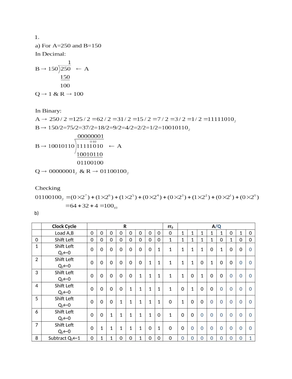
b)
Clock Cycle
R
rr0
A/Q
Load A,B
0
0
0
0
0
0
0
0
0
1
1
1
1
1
0
1
0
0
Shift Left
0
0
0
0
0
0
0
0
1
1
1
1
1
0
1
0
0
1
Shift Left
Q0←0
0
0
0
0
0
0
0
1
1
1
1
1
0
1
0
0
0
2
Shift Left
Q0←0
0
0
0
0
0
0
1
1
1
1
1
0
1
0
0
0
0
3
Shift Left
Q0←0
0
0
0
0
0
1
1
1
1
1
0
1
0
0
0
0
0
4
Shift Left
Q0←0
0
0
0
0
1
1
1
1
1
0
1
0
0
0
0
0
0
5
Shift Left
Q0←0
0
0
0
1
1
1
1
1
0
1
0
0
0
0
0
0
0
6
Shift Left
Q0←0
0
0
1
1
1
1
1
0
1
0
0
0
0
0
0
0
0
7
Shift Left
Q0←0
0
1
1
1
1
1
0
1
0
0
0
0
0
0
0
0
0
8
Subtract Q0←1
0
1
1
0
0
1
0
0
0
0
0
0
0
0
0
0
1
Brief Explanation of the Design
Our program contains many components: A shift register, B register, R shift register,
Multiplexer, Q shift register, 1 bit adder, 8 bit adder, 4 bit counter, state machine and finally the
Divider entity which joins all the other entities.
Our program uses the concept of sequential circuits to implement the design of an 8 and
32 bit divider. The Divider entity joins all the components in a structural design. The most
important part of these components is the state machine entity. This entity controls all the
signals that allow loading and shifting in each of the components. The counter entity controls
the number of iterations of the divider. So when count is 1, it means that the division process is
over and no further operations are needed.
Another important part of this design is not a component but the input signal ‘s’. This
signal tells the state machine to stop or to keep on iterating. Another important notion in this
project is to always cover all possible cases when you are writing an “if statement.” This came
into play when we were controlling the A Shift Register and R Shift Register. The 8 bit adder
uses the generate function to use eight 1 bit adders.
The rest of the design is fairly simple and self-explanatory. It has all been designed in the
way requested. We have used various signals to connect all the components together and of
course the main controller of all these signals is the state machine. The Divider entity has an
extra input which is the s input, which was explained about above.
The explanation of all the test benches is found above each test bench of the each
component of the 8 bit adder.
Full Adder
library IEEE;
use IEEE.std_logic_1164.all;
entity full_adder is
port (
X: in STD_LOGIC;
Y: in STD_LOGIC;
CIN: in STD_LOGIC;
sum: out STD_LOGIC;
COUT: out STD_LOGIC
);
end full_adder;
architecture full_adder_arch of full_adder is
begin
sum <= (X XOR Y) XOR CIN ;
COUT <= (X AND Y) OR (X AND CIN) OR (Y AND CIN);
end full_adder_arch;
8 Bit Adder
library ieee;
use ieee.std_logic_1164.all;
entity adder is
port(x,y:in std_logic_vector(7 downto 0);
c0:in std_logic; c8:out std_logic;
sum:out std_logic_vector(7 downto 0));
end adder;
architecture adder_arch of adder is
component full_adder
port (
X: in STD_LOGIC;
Y: in STD_LOGIC;
CIN: in STD_LOGIC;
sum: out STD_LOGIC;
COUT: out STD_LOGIC);
end component;
signal c:std_logic_vector(0 to 8);
begin
g: for b in 0 to 7 generate
u: full_adder port map(x=>x(b),y=>y(b),cin=>c(b),sum=>sum(b),cout=>c(b+1));
end generate;
c(0)<=c0;
c8<=c(8);
end adder_arch;
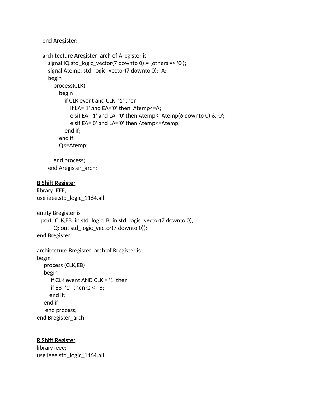
A Shift Register
library ieee;
use ieee.std_logic_1164.all;
entity Aregister is
port(LA:in std_logic;EA:in std_logic;
CLK:in std_logic;A:in std_logic_vector(7 downto 0);
Q:out std_logic_vector(7 downto 0));
end Aregister;
architecture Aregister_arch of Aregister is
signal IQ:std_logic_vector(7 downto 0):= (others => '0');
signal Atemp: std_logic_vector(7 downto 0):=A;
begin
process(CLK)
begin
if CLK'event and CLK='1' then
if LA='1' and EA='0' then Atemp<=A;
elsif EA='1' and LA='0' then Atemp<=Atemp(6 downto 0) & '0';
elsif EA='0' and LA='0' then Atemp<=Atemp;
end if;
end if;
Q<=Atemp;
end process;
end Aregister_arch;
B Shift Register
library IEEE;
use ieee.std_logic_1164.all;
entity Bregister is
port (CLK,EB: in std_logic; B: in std_logic_vector(7 downto 0);
Q: out std_logic_vector(7 downto 0));
end Bregister;
architecture Bregister_arch of Bregister is
begin
process (CLK,EB)
begin
if CLK'event AND CLK = '1' then
if EB='1' then Q <= B;
end if;
end if;
end process;
end Bregister_arch;
R Shift Register
library ieee;
use ieee.std_logic_1164.all;
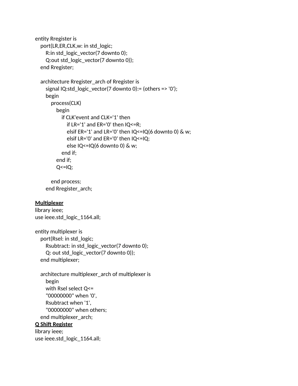
entity Rregister is
port(LR,ER,CLK,w: in std_logic;
R:in std_logic_vector(7 downto 0);
Q:out std_logic_vector(7 downto 0));
end Rregister;
architecture Rregister_arch of Rregister is
signal IQ:std_logic_vector(7 downto 0):= (others => '0');
begin
process(CLK)
begin
if CLK'event and CLK='1' then
if LR='1' and ER='0' then IQ<=R;
elsif ER='1' and LR='0' then IQ<=IQ(6 downto 0) & w;
elsif LR='0' and ER='0' then IQ<=IQ;
else IQ<=IQ(6 downto 0) & w;
end if;
end if;
Q<=IQ;
end process;
end Rregister_arch;
Multiplexer
library ieee;
use ieee.std_logic_1164.all;
entity multiplexer is
port(Rsel: in std_logic;
Rsubtract: in std_logic_vector(7 downto 0);
Q: out std_logic_vector(7 downto 0));
end multiplexer;
architecture multiplexer_arch of multiplexer is
begin
with Rsel select Q<=
"00000000" when '0',
Rsubtract when '1',
"00000000" when others;
end multiplexer_arch;
Q Shift Register
library ieee;
use ieee.std_logic_1164.all;
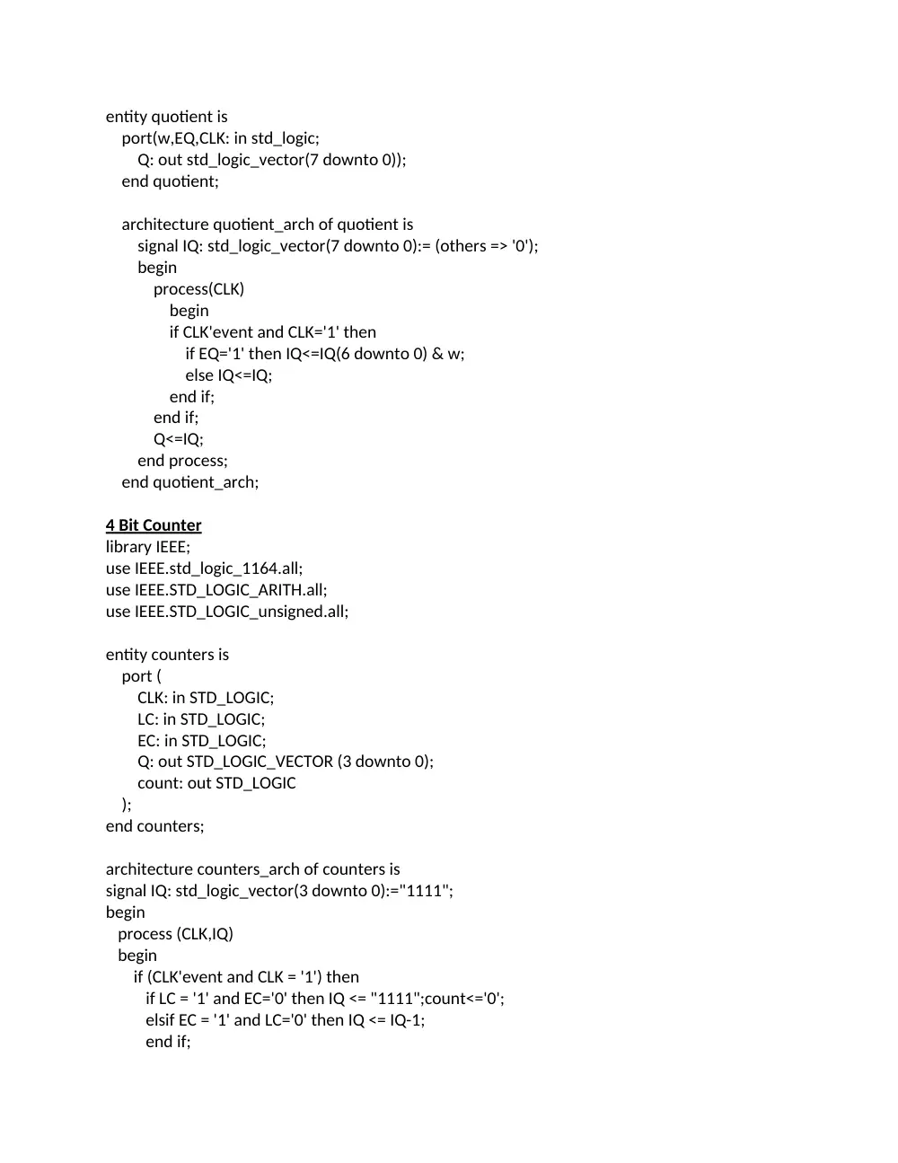
entity quotient is
port(w,EQ,CLK: in std_logic;
Q: out std_logic_vector(7 downto 0));
end quotient;
architecture quotient_arch of quotient is
signal IQ: std_logic_vector(7 downto 0):= (others => '0');
begin
process(CLK)
begin
if CLK'event and CLK='1' then
if EQ='1' then IQ<=IQ(6 downto 0) & w;
else IQ<=IQ;
end if;
end if;
Q<=IQ;
end process;
end quotient_arch;
4 Bit Counter
library IEEE;
use IEEE.std_logic_1164.all;
use IEEE.STD_LOGIC_ARITH.all;
use IEEE.STD_LOGIC_unsigned.all;
entity counters is
port (
CLK: in STD_LOGIC;
LC: in STD_LOGIC;
EC: in STD_LOGIC;
Q: out STD_LOGIC_VECTOR (3 downto 0);
count: out STD_LOGIC
);
end counters;
architecture counters_arch of counters is
signal IQ: std_logic_vector(3 downto 0):="1111";
begin
process (CLK,IQ)
begin
if (CLK'event and CLK = '1') then
if LC = '1' and EC='0' then IQ <= "1111";count<='0';
elsif EC = '1' and LC='0' then IQ <= IQ-1;
end if;
end if;
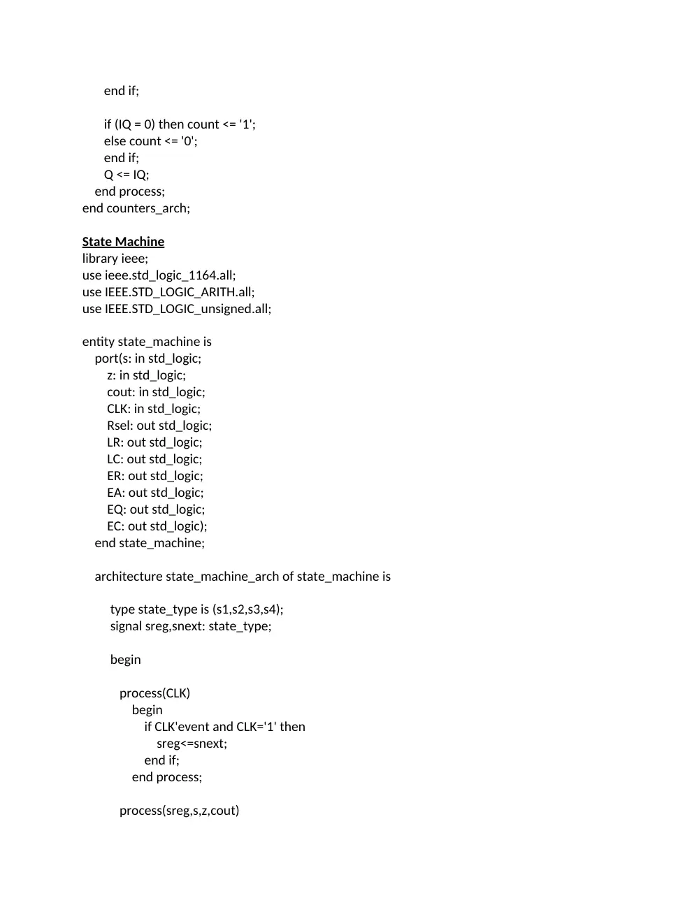
if (IQ = 0) then count <= '1';
else count <= '0';
end if;
Q <= IQ;
end process;
end counters_arch;
State Machine
library ieee;
use ieee.std_logic_1164.all;
use IEEE.STD_LOGIC_ARITH.all;
use IEEE.STD_LOGIC_unsigned.all;
entity state_machine is
port(s: in std_logic;
z: in std_logic;
cout: in std_logic;
CLK: in std_logic;
Rsel: out std_logic;
LR: out std_logic;
LC: out std_logic;
ER: out std_logic;
EA: out std_logic;
EQ: out std_logic;
EC: out std_logic);
end state_machine;
architecture state_machine_arch of state_machine is
type state_type is (s1,s2,s3,s4);
signal sreg,snext: state_type;
begin
process(CLK)
begin
if CLK'event and CLK='1' then
sreg<=snext;
end if;
end process;
process(sreg,s,z,cout)
begin
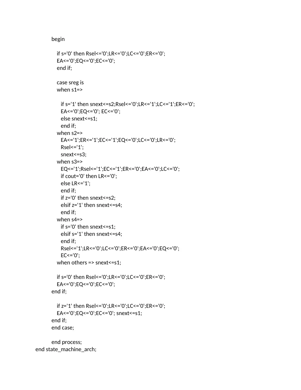
if s='0' then Rsel<='0';LR<='0';LC<='0';ER<='0';
EA<='0';EQ<='0';EC<='0';
end if;
case sreg is
when s1=>
if s='1' then snext<=s2;Rsel<='0';LR<='1';LC<='1';ER<='0';
EA<='0';EQ<='0'; EC<='0';
else snext<=s1;
end if;
when s2=>
EA<='1';ER<='1';EC<='1';EQ<='0';LC<='0';LR<='0';
Rsel<='1';
snext<=s3;
when s3=>
EQ<='1';Rsel<='1';EC<='1';ER<='0';EA<='0';LC<='0';
if cout='0' then LR<='0';
else LR<='1';
end if;
if z='0' then snext<=s2;
elsif z='1' then snext<=s4;
end if;
when s4=>
if s='0' then snext<=s1;
elsif s='1' then snext<=s4;
end if;
Rsel<='1';LR<='0';LC<='0';ER<='0';EA<='0';EQ<='0';
EC<='0';
when others => snext<=s1;
if s='0' then Rsel<='0';LR<='0';LC<='0';ER<='0';
EA<='0';EQ<='0';EC<='0';
end if;
if z='1' then Rsel<='0';LR<='0';LC<='0';ER<='0';
EA<='0';EQ<='0';EC<='0'; snext<=s1;
end if;
end case;
end process;
end state_machine_arch;
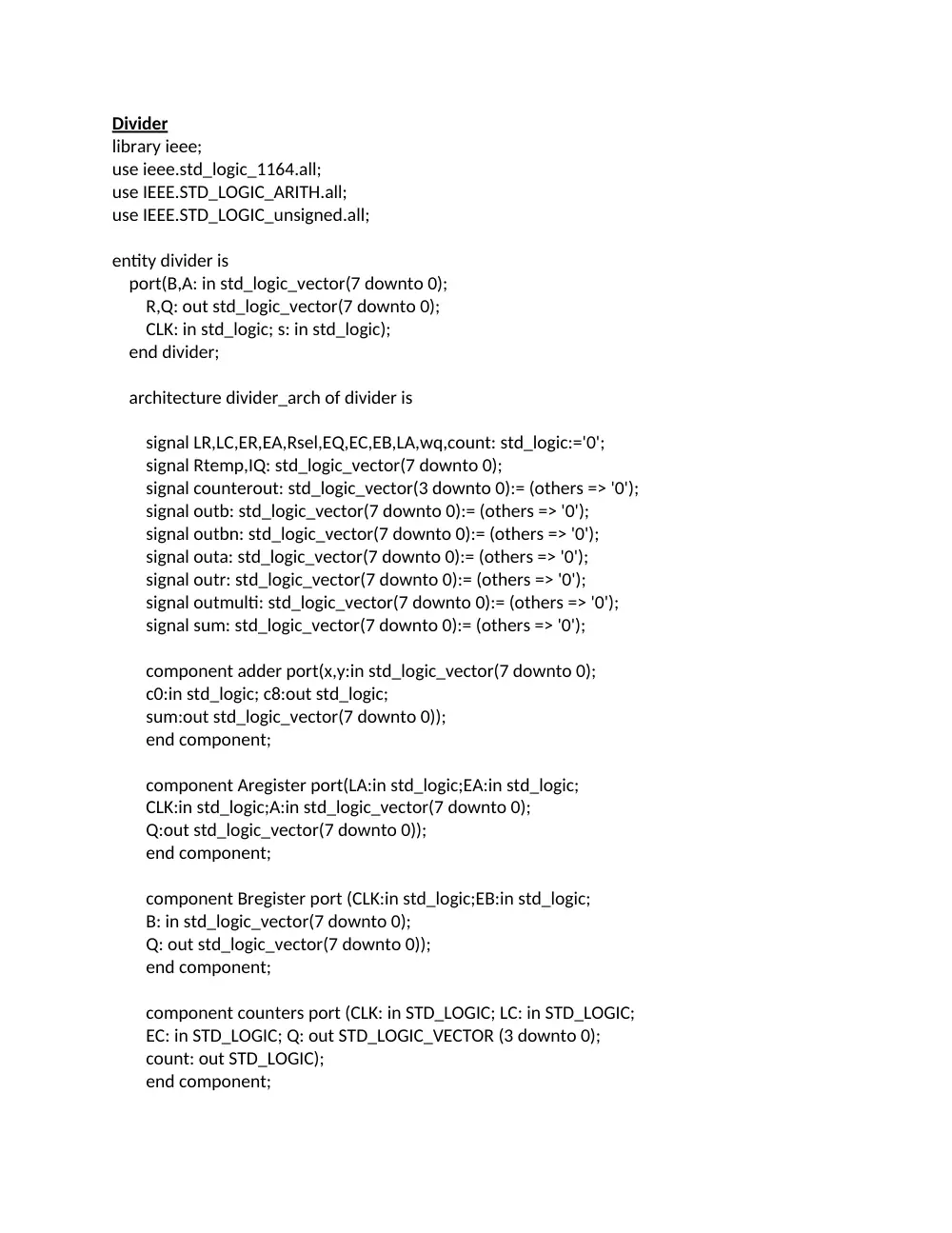
Divider
library ieee;
use ieee.std_logic_1164.all;
use IEEE.STD_LOGIC_ARITH.all;
use IEEE.STD_LOGIC_unsigned.all;
entity divider is
port(B,A: in std_logic_vector(7 downto 0);
R,Q: out std_logic_vector(7 downto 0);
CLK: in std_logic; s: in std_logic);
end divider;
architecture divider_arch of divider is
signal LR,LC,ER,EA,Rsel,EQ,EC,EB,LA,wq,count: std_logic:='0';
signal Rtemp,IQ: std_logic_vector(7 downto 0);
signal counterout: std_logic_vector(3 downto 0):= (others => '0');
signal outb: std_logic_vector(7 downto 0):= (others => '0');
signal outbn: std_logic_vector(7 downto 0):= (others => '0');
signal outa: std_logic_vector(7 downto 0):= (others => '0');
signal outr: std_logic_vector(7 downto 0):= (others => '0');
signal outmulti: std_logic_vector(7 downto 0):= (others => '0');
signal sum: std_logic_vector(7 downto 0):= (others => '0');
component adder port(x,y:in std_logic_vector(7 downto 0);
c0:in std_logic; c8:out std_logic;
sum:out std_logic_vector(7 downto 0));
end component;
component Aregister port(LA:in std_logic;EA:in std_logic;
CLK:in std_logic;A:in std_logic_vector(7 downto 0);
Q:out std_logic_vector(7 downto 0));
end component;
component Bregister port (CLK:in std_logic;EB:in std_logic;
B: in std_logic_vector(7 downto 0);
Q: out std_logic_vector(7 downto 0));
end component;
component counters port (CLK: in STD_LOGIC; LC: in STD_LOGIC;
EC: in STD_LOGIC; Q: out STD_LOGIC_VECTOR (3 downto 0);
count: out STD_LOGIC);
end component;
component multiplexer port(Rsel: in std_logic;
Rsubtract: in std_logic_vector(7 downto 0);
Q: out std_logic_vector(7 downto 0));
end component;
component quotient port(w,EQ,CLK: in std_logic;
Q: out std_logic_vector(7 downto 0));
end component;
component Rregister port (LR,ER,CLK,w: in std_logic;
R:in std_logic_vector(7 downto 0); Q:out std_logic_vector(7 downto 0));
end component;
component state_machine port(s: in std_logic;
z: in std_logic; cout: in std_logic; CLK: in std_logic;
Rsel: out std_logic; LR: out std_logic; LC: out std_logic;
ER: out std_logic; EA: out std_logic; EQ: out std_logic;
EC: out std_logic);
end component;
begin
EB<='1' when counterout=15;
U1: Bregister port map(CLK,EB,B,outb);
U2: Aregister port map(LA,EA,CLK,A,outa);
U3: Rregister port map(LR,ER,CLK,outa(7),outmulti,outr);
U4: multiplexer port map(Rsel,sum,outmulti);
outbn<=not outb;
U5: adder port map(outbn,outr,'1',wq,sum);
U6: quotient port map(wq,EQ,CLK,IQ);
U7: counters port map(CLK,LC,EC,counterout,count);
U8: state_machine port map(s,count,wq,CLK,Rsel,LR,LC,ER,EA,EQ,EC);
Q<=IQ;
R<=outr;
end divider_arch;
8 Bit Adder Test Bench
In this test bench it is not practical to test all the cases. That is why we tested random
cases which contain carry outs and which don’t, so as to test all the extreme possibilities.
library ieee;
use ieee.std_logic_1164.all;
entity adder_tb is
end adder_tb;
architecture adder_tb_arch of adder_tb is
component adder
port ( X : in std_logic_vector(7 downto 0);
Y : in std_logic_vector(7 downto 0);
C0 : in std_logic;
sum : out std_logic_vector(7 downto 0);
C8 : out std_logic );
end component;
signal X : std_logic_vector(7 downto 0) := "00000000";
signal Y : std_logic_vector(7 downto 0) := "00000000";
signal C0 : std_logic := '0';
signal sum : std_logic_vector(7 downto 0);
signal C8 : std_logic;
begin
UUT : adder
port map (X => X, Y => Y, C0 => C0, sum => sum, C8 => C8);
process
begin
X <= "00000000"; wait for 10 ns; Y <= "00000001"; wait for 10 ns;
X <= "00000010"; wait for 10 ns; Y <= "00000011"; wait for 10 ns;
X <= "00000100"; wait for 10 ns; Y <= "00000101"; wait for 10 ns;
X <= "00000110"; wait for 10 ns; Y <= "01100001"; wait for 10 ns;
X <= "10000000"; wait for 10 ns; Y <= "11111001"; wait for 10 ns;
X <= "10001010"; wait for 10 ns; Y <= "10110001"; wait for 10 ns;
X <= "11010100"; wait for 10 ns; Y <= "10011101"; wait for 10 ns;
X <= "11110010"; wait for 10 ns; Y <= "11110011"; wait for 10 ns;
wait;
end process;
end adder_tb_arch;
8 Bit Full Adder Wave Form
A Shift Register Test Bench
This test case is very simple. All we did was input an 8 bit string and change the EA signal
from 0 to 1. This signal of course, controls shifting. Every time this signal changed to one and
the clock changed to 1 the output shifted to the left, indicating that the component is
functioning properly.
ibrary ieee;
use ieee.std_logic_1164.all;
entity Aregister_tb is
end Aregister_tb;
architecture Aregister_tb_arch of Aregister_tb is
signal CLK,LA,EA: std_logic;
signal Q: std_logic_vector(7 downto 0);
signal A: std_logic_vector(7 downto 0):="11001011";
component Aregister
port(LA:in std_logic;EA:in std_logic;
CLK:in std_logic;A:in std_logic_vector(7 downto 0);
Q:out std_logic_vector(7 downto 0));
end component;
begin
UUT: Aregister port map (LA=>LA,EA=>EA,CLK=>CLK,A=>A,Q=>Q);
process
begin
CLK<='1'; wait for 5 ns;
CLK<='0'; wait for 5 ns;
end process;
process
begin
EA<='0'; wait for 20 ns;
LA<='1'; wait for 20 ns;
LA<='0'; wait for 20 ns;
EA<='1'; wait for 20 ns;
EA<='0'; wait for 20 ns;
EA<='1'; wait for 20 ns;
EA<='0'; wait for 20 ns;
EA<='1'; wait for 20 ns;
EA<='0'; wait for 20 ns;
EA<='1'; wait for 20 ns;
EA<='0'; wait for 20 ns;
EA<='1'; wait for 20 ns;
EA<='0'; wait for 20 ns;
EA<='1'; wait for 20 ns;
EA<='0'; wait for 20 ns;
EA<='1'; wait for 20 ns;
EA<='0'; wait for 20 ns;
EA<='1'; wait for 20 ns
wait;
end process;
end Aregister_tb_arch;
A Shift Register Wave Form
B Shift Register Test Bench
This code is very simple and straight forward. We give a bit string and then control the
input signal EB. We first set it to 0 and then we set it to 1. After that we observe the output, and
the Register functions as it should function which is a parallel in parallel out register.
library ieee;
use ieee.std_logic_1164.all;
entity Bregister_tb is
end Bregister_tb;
architecture Bregister_tb_arch of Bregister_tb is
signal CLK,EB: std_logic;
signal B: std_logic_vector(7 downto 0):="11001011";
signal Q: std_logic_vector(7 downto 0);
component Bregister
port (CLK,EB: in std_logic; B: in std_logic_vector(7 downto 0);
Q: out std_logic_vector(7 downto 0):="00000000");
end component;
begin
UUT: Bregister port map (CLK=>CLK,EB=>EB,B=>B,Q=>Q);
process
begin
CLK<='1'; wait for 5 ns;
CLK<='0'; wait for 5 ns;
end process;
process
begin
EB<='0'; wait for 20 ns;
EB<='1'; wait for 20 ns;
wait;
end process;
end Bregister_tb_arch;
B Shift Register Waveform
R Shift Register Test Bench
In this component we first assign a bit string, and then we load it by setting LR to 1. Then
we simply change ER to 1 then 0, and this shifts the output leftwards just as it should, indicating
proper design.
library ieee;
use ieee.std_logic_1164.all;
entity Rregister_tb is
end Rregister_tb;
architecture Rregister_tb_arch of Rregister_tb is
signal CLK,ER,LR,w: std_logic;
signal R: std_logic_vector(7 downto 0):="11001011";
signal Q: std_logic_vector(7 downto 0);
component Rregister
port(LR,ER,CLK,w: in std_logic;
R:in std_logic_vector(7 downto 0);
Q:out std_logic_vector(7 downto 0));
end component;
begin
UUT: Rregister port map (LR=>LR,ER=>ER,CLK=>CLK,w=>w,R=>R,Q=>Q);
process
begin
CLK<='1'; wait for 5 ns;
CLK<='0'; wait for 5 ns;
end process;
process
begin
w<='0'; wait for 10 ns;
ER<='0'; wait for 20 ns;
LR<='1'; wait for 20 ns;
LR<='0'; wait for 20 ns;
ER<='1'; wait for 20 ns;
ER<='0'; wait for 20 ns;
ER<='1'; wait for 20 ns;
ER<='0'; wait for 20 ns;
ER<='1'; wait for 20 ns;
ER<='0'; wait for 20 ns;
ER<='1'; wait for 20 ns;
ER<='0'; wait for 20 ns;
ER<='1'; wait for 20 ns;
ER<='0'; wait for 20 ns;
ER<='1'; wait for 20 ns;
ER<='0'; wait for 20 ns;
ER<='1'; wait for 20 ns;
ER<='0'; wait for 20 ns;
ER<='1'; wait for 20 ns;
wait;
end process;
end Rregister_tb_arch;
R Shift Register Waveform
Q Shift Register Test Bench
The implementation of this test bench is similar to the implementation of the test bench
for the R and A shift registers. Every time EQ changes to 1 and the clock is at a rising edge. The
quotient is shifted left and the carry out of the adder is added to the quotient of the bit string
from the right.
library ieee;
use ieee.std_logic_1164.all;
entity Quotient_tb is
end Quotient_tb;
architecture Quotient_tb_arch of Quotient_tb is
signal CLK,EQ: std_logic;
signal w: std_logic:='1';
signal Q: std_logic_vector(7 downto 0);
component Quotient
port(w,EQ,CLK: in std_logic;
Q: out std_logic_vector(7 downto 0));
end component;
begin
UUT: Quotient port map (w=>w,EQ=>EQ,CLK=>CLK,Q=>Q);
process
begin
CLK<='1'; wait for 5 ns;
CLK<='0'; wait for 5 ns;
end process;
process
begin
EQ<='0'; wait for 20 ns;
EQ<='1'; wait for 20 ns;
EQ<='0'; wait for 20 ns;
EQ<='1'; wait for 20 ns;
EQ<='0'; wait for 20 ns;
EQ<='1'; wait for 20 ns;
EQ<='0'; wait for 20 ns;
EQ<='1'; wait for 20 ns;
EQ<='0'; wait for 20 ns;
EQ<='1'; wait for 20 ns;
EQ<='0'; wait for 20 ns;
EQ<='1'; wait for 20 ns;
EQ<='0'; wait for 20 ns;
EQ<='1'; wait for 20 ns;
EQ<='0'; wait for 20 ns;
EQ<='1'; wait for 20 ns;
wait;
end process;
end Quotient_tb_arch;
Q Shift Register Waveform
Multiplexer Test Bench
This test bench simply loads an all 0 bit string or an all 1s bit string depending on the
Rsel signal. In the test bench we first set Rsel to 0 and then we set it to 1, and we observe that
first the all 0s bit string is output and then the all 1s bit string is output. This of course indicates
proper functioning.
library ieee;
use ieee.std_logic_1164.all;
entity multiplexer_tb is
end multiplexer_tb;
architecture multiplexer_tb_arch of multiplexer_tb is
signal Rsel: std_logic:='0';
signal Rsubtract,Q: std_logic_vector(7 downto 0):="11111111";
component multiplexer
port(Rsel: in std_logic;
Rsubtract: in std_logic_vector(7 downto 0);
Q: out std_logic_vector(7 downto 0));
end component;
begin
UUT: multiplexer port map(Rsel=>Rsel,Rsubtract=>Rsubtract,Q=>Q);
process
begin
Rsel<='1'; wait for 10 ns;
Rsel<='0'; wait for 20 ns;
wait;
end process;
end multiplexer_tb_arch;
Multiplexer Wave Form
4 Bit Counter Test Bench
Once Again this entity has two signals that control it, alongside the clock. We first set LC
to 1 to make everything equal to its initial value. Then after that we set EC to 1 and then to 0,
and in the output we realize that the 4 bit output decrements since this counter doesn’t
increment but decrements. When the output reaches 0 then the count is set to 1 indicating that
16 iterations have been achieved, and that the division process should stop.
library ieee;
use ieee.std_logic_1164.all;
entity counters_tb is
end counters_tb;
architecture counters_tb_arch of counters_tb is
signal CLK,LC,EC,count: std_logic;
signal Q: std_logic_vector(3 downto 0);
component counters
port (CLK: in STD_LOGIC;
LC: in STD_LOGIC;
EC: in STD_LOGIC;
Q: out STD_LOGIC_VECTOR (3 downto 0);
count: out STD_LOGIC);
end component;
begin
UUT: counters port map(CLK=>CLK,LC=>LC,EC=>EC,Q=>Q,count=>count);
process
begin
CLK<='1'; wait for 5 ns;
CLK<='0'; wait for 5 ns;
end process;
process
begin
LC<='1'; wait for 20 ns;
LC<='0'; wait for 20 ns;
EC<='0'; wait for 20 ns;
EC<='1'; wait for 20 ns;
EC<='0'; wait for 20 ns;
EC<='1'; wait for 20 ns;
EC<='0'; wait for 20 ns;
EC<='1'; wait for 20 ns;
wait;
end process;
end counters_tb_arch;
4 Bit Counter Wave Form
State Machine Test Bench
Although the code for this entity is big, its test bench is very small. We simply need to set s to 1
and z to 0 so that we can allow the iteration process to take place. Based on this iteration all the
output signals are set to the value they should be set to during each state. As you can see all
the state outputs are correct.
library ieee;
use ieee.std_logic_1164.all;
entity state_machine_tb is
end;
architecture state_machine_tb_arch of state_machine_tb is
signal CLK,s,z,cout,Rsel,LR,LC,ER,EA,EQ,EC: std_logic:='0';
component state_machine
port(s: in std_logic;
z: in std_logic;
cout: in std_logic;
CLK: in std_logic;
Rsel: out std_logic;
LR: out std_logic;
LC: out std_logic;
ER: out std_logic;
EA: out std_logic;
EQ: out std_logic;
EC: out std_logic);
end component;
begin
UUT: state_machine port map (s=>s,z=>z,cout=>cout,CLK=>CLK,
Rsel=>Rsel,LR=>LR,LC=>LC,ER=>ER,EA=>EA,EQ=>EQ,EC=>EC);
process
begin
CLK<='1'; wait for 5 ns;
CLK<='0'; wait for 5 ns;
end process;
process
begin
s<='1'; wait for 100 ns;
z<='0'; wait for 150 ns;
cout<='0'; wait for 100 ns;
z<='1'; wait for 150 ns;
s<='0'; wait for 20 ns;
wait;
end process;
end state_machine_tb_arch;
State Machine Wave Form
Divider Test Bench
In this entity we first reset everything to 0 by setting s to 0. After that we set s to 1 so
that the division can take place. Of course we must set A (Dividend) and B (Divisor) to their
corresponding values. In this case A = 140 and B = 9. Of course as you can realize the results
obtained are exactly the same results as obtained on the first page of the question sheet for
this project.
library ieee;
use ieee.std_logic_1164.all;
entity divider_tb is
end divider_tb;
architecture divider_tb_arch of divider_tb is
component divider port(B,A: in std_logic_vector(7 downto 0);
R,Q: out std_logic_vector(7 downto 0);CLK: in std_logic;
s: in std_logic);
end component;
signal A: std_logic_vector(7 downto 0):="10001100";
signal B: std_logic_vector(7 downto 0):="00001001";
signal Q: std_logic_vector(7 downto 0);
signal R: std_logic_vector(7 downto 0);
signal CLK: std_logic;
signal s: std_logic;
begin
U1: divider port map(B=>B,A=>A,R=>R,Q=>Q,CLK=>CLK,s=>s);
U2: process
begin
CLK<='1'; wait for 10 ns;
CLK<='0'; wait for 10 ns;
end process;
U3: process
begin
s<='0'; wait for 60 ns;
s<='1'; wait for 60 ns;
A<="10001100"; wait for 150 ns;
B<="00001001"; wait for 150 ns;
s<='0'; wait for 60 ns;
end process;
end divider_tb_arch;
Divider Wave Form
Divider Test Bench 2
A = 250 and B = 150. The output is correct indicating proper design.
library ieee;
use ieee.std_logic_1164.all;
entity divider2_tb is
end divider2_tb;
architecture divider2_tb_arch of divider2_tb is
component divider port(B,A: in std_logic_vector(7 downto 0);
R,Q: out std_logic_vector(7 downto 0);CLK: in std_logic;
s: in std_logic);
end component;
signal A: std_logic_vector(7 downto 0):="11111010";
signal B: std_logic_vector(7 downto 0):="10010110";
signal Q: std_logic_vector(7 downto 0);
signal R: std_logic_vector(7 downto 0);
signal CLK: std_logic;
signal s: std_logic;
begin
U1: divider port map(B=>B,A=>A,R=>R,Q=>Q,CLK=>CLK,s=>s);
U2: process
begin
CLK<='1'; wait for 10 ns;
CLK<='0'; wait for 10 ns;
end process;
U3: process
begin
s<='0'; wait for 60 ns;
s<='1'; wait for 60 ns;
A<="11111010"; wait for 150 ns;
B<="10010110"; wait for 150 ns;
s<='0'; wait for 60 ns;
end process;
end divider2_tb_arch;
Divider Wave Form 2
Divider Test Bench 3
A = 250 and B = 125. The output is correct indicating proper design.
library ieee;
use ieee.std_logic_1164.all;
entity divider3_tb is
end divider3_tb;
architecture divider3_tb_arch of divider3_tb is
component divider port(B,A: in std_logic_vector(7 downto 0);
R,Q: out std_logic_vector(7 downto 0);CLK: in std_logic;
s: in std_logic);
end component;
signal A: std_logic_vector(7 downto 0):="11111010";
signal B: std_logic_vector(7 downto 0):="01111101";
signal Q: std_logic_vector(7 downto 0);
signal R: std_logic_vector(7 downto 0);
signal CLK: std_logic;
signal s: std_logic;
begin
U1: divider port map(B=>B,A=>A,R=>R,Q=>Q,CLK=>CLK,s=>s);
U2: process
begin
CLK<='1'; wait for 10 ns;
CLK<='0'; wait for 10 ns;
end process;
U3: process
begin
s<='0'; wait for 60 ns;
s<='1'; wait for 60 ns;
A<="11111010"; wait for 150 ns;
B<="01111101"; wait for 150 ns;
s<='0'; wait for 60 ns;
end process;
end divider3_tb_arch;
Divider Wave Form 3
Divider Test Bench 4
A = 15 and B = 30. The output is correct indicating proper design.
library ieee;
use ieee.std_logic_1164.all;
entity divider4_tb is
end divider4_tb;
architecture divider4_tb_arch of divider4_tb is
component divider port(B,A: in std_logic_vector(7 downto 0);
R,Q: out std_logic_vector(7 downto 0);CLK: in std_logic;
s: in std_logic);
end component;
signal A: std_logic_vector(7 downto 0):="00001111";
signal B: std_logic_vector(7 downto 0):="00011110";
signal Q: std_logic_vector(7 downto 0);
signal R: std_logic_vector(7 downto 0);
signal CLK: std_logic;
signal s: std_logic;
begin
U1: divider port map(B=>B,A=>A,R=>R,Q=>Q,CLK=>CLK,s=>s);
U2: process
begin
CLK<='1'; wait for 10 ns;
CLK<='0'; wait for 10 ns;
end process;
U3: process
begin
s<='0'; wait for 60 ns;
s<='1'; wait for 60 ns;
A<="00001111"; wait for 150 ns;
B<="00011110"; wait for 150 ns;
s<='0'; wait for 60 ns;
end process;
end divider4_tb_arch;
Divider Wave Form 4
BONUS
For this part we will not be providing any test benches for each of the entities since they
are just like the test benches of the 8 bit divider. Now the only change that we made, since it
was the only logical thing to do, was to change every number that was 7 to 31 and every
number that was 8 to 32 and every number that was 3 to 5. This pretty much looked logical,
and at the same time it worked. So our assumption was correct and the method in which we
implemented this part was correct, so no other changes were required.
32 Full Adder
library IEEE;
use IEEE.std_logic_1164.all;
entity full_adder32 is
port (
X: in STD_LOGIC;
Y: in STD_LOGIC;
CIN: in STD_LOGIC;
sum: out STD_LOGIC;
COUT: out STD_LOGIC
);
end full_adder32;
architecture full_adder32_arch of full_adder32 is
begin
sum <= (X XOR Y) XOR CIN ;
COUT <= (X AND Y) OR (X AND CIN) OR (Y AND CIN);
end full_adder32_arch;
32 Bit Adder
library ieee;
use ieee.std_logic_1164.all;
entity adder32 is
port(x,y:in std_logic_vector(31 downto 0);
c0:in std_logic; c32:out std_logic;
sum:out std_logic_vector(31 downto 0));
end adder32;
architecture adder32_arch of adder32 is
component full_adder32
port (
X: in STD_LOGIC;
Y: in STD_LOGIC;
CIN: in STD_LOGIC;
sum: out STD_LOGIC;
COUT: out STD_LOGIC);
end component;
signal c:std_logic_vector(0 to 32);
begin
g: for b in 0 to 31 generate
u: full_adder32 port map(x=>x(b),y=>y(b),cin=>c(b),sum=>sum(b),cout=>c(b+1));
end generate;
c(0)<=c0;
c32<=c(32);
end adder32_arch;
32 Bit A Shift Register
library ieee;
use ieee.std_logic_1164.all;
entity Aregister32 is
port(LA:in std_logic;EA:in std_logic;
CLK:in std_logic;A:in std_logic_vector(31 downto 0);
Q:out std_logic_vector(31 downto 0));
end Aregister32;
architecture Aregister32_arch of Aregister32 is
signal IQ:std_logic_vector(31 downto 0):= (others => '0');
signal Atemp: std_logic_vector(31 downto 0):=A;
begin
process(CLK)
begin
if CLK'event and CLK='1' then
if LA='1' and EA='0' then Atemp<=A;
elsif EA='1' and LA='0' then Atemp<=Atemp(30 downto 0) & '0';
elsif EA='0' and LA='0' then Atemp<=Atemp;
end if;
end if;
Q<=Atemp;
end process;
end Aregister32_arch;
32 Bit B Shift Register
library IEEE;
use ieee.std_logic_1164.all;
entity Bregister32 is
port (CLK,EB: in std_logic; B: in std_logic_vector(31 downto 0);
Q: out std_logic_vector(31 downto 0));
end Bregister32;
architecture Bregister32_arch of Bregister32 is
begin
process (CLK,EB)
begin
if CLK'event AND CLK = '1' then
if EB='1' then Q <= B;
end if;
end if;
end process;
end Bregister32_arch;
6 Bit Counter
library IEEE;
use IEEE.std_logic_1164.all;
use IEEE.STD_LOGIC_ARITH.all;
use IEEE.STD_LOGIC_unsigned.all;
entity counters32 is
port (
CLK: in STD_LOGIC;
LC: in STD_LOGIC;
EC: in STD_LOGIC;
Q: out STD_LOGIC_VECTOR (5 downto 0);
count: out STD_LOGIC
);
end counters32;
architecture counters32_arch of counters32 is
signal IQ: std_logic_vector(5 downto 0):="111111";
begin
process (CLK,IQ)
begin
if (CLK'event and CLK = '1') then
if LC = '1' and EC='0' then IQ <= "111111";count<='0';
elsif EC = '1' and LC='0' then IQ <= IQ-1;
end if;
end if;
if (IQ = 0) then count <= '1';
else count <= '0';
end if;
Q <= IQ;
end process;
end counters32_arch;
Multiplexer 32
library ieee;
use ieee.std_logic_1164.all;
entity multiplexer32 is
port(Rsel: in std_logic;
Rsubtract: in std_logic_vector(31 downto 0);
Q: out std_logic_vector(31 downto 0));
end multiplexer32;
architecture multiplexer32_arch of multiplexer32 is
begin
with Rsel select Q<=
(others => '0') when '0',
Rsubtract when '1',
(others => '0') when others;
end multiplexer32_arch;
32 Bit Quotient Shift Register
library ieee;
use ieee.std_logic_1164.all;
entity quotient32 is
port(w,EQ,CLK: in std_logic;
Q: out std_logic_vector(31 downto 0));
end quotient32;
architecture quotient32_arch of quotient32 is
signal IQ: std_logic_vector(31 downto 0):= (others => '0');
begin
process(CLK)
begin
if CLK'event and CLK='1' then
if EQ='1' then IQ<=IQ(30 downto 0) & w;
else IQ<=IQ;
end if;
end if;
Q<=IQ;
end process;
end quotient32_arch;
32 Bit R Shift Register
library ieee;
use ieee.std_logic_1164.all;
entity Rregister32 is
port(LR,ER,CLK,w: in std_logic;
R:in std_logic_vector(31 downto 0);
Q:out std_logic_vector(31 downto 0));
end Rregister32;
architecture Rregister32_arch of Rregister32 is
signal IQ:std_logic_vector(31 downto 0):= (others => '0');
begin
process(CLK)
begin
if CLK'event and CLK='1' then
if LR='1' and ER='0' then IQ<=R;
elsif ER='1' and LR='0' then IQ<=IQ(30 downto 0) & w;
elsif LR='0' and ER='0' then IQ<=IQ;
else IQ<=IQ(30 downto 0) & w;
end if;
end if;
Q<=IQ;
end process;
end Rregister32_arch;
State Machine 32
library ieee;
use ieee.std_logic_1164.all;
use IEEE.STD_LOGIC_ARITH.all;
use IEEE.STD_LOGIC_unsigned.all;
entity state_machine32 is
port(s: in std_logic;
z: in std_logic;
cout: in std_logic;
CLK: in std_logic;
Rsel: out std_logic;
LR: out std_logic;
LC: out std_logic;
ER: out std_logic;
EA: out std_logic;
EQ: out std_logic;
EC: out std_logic);
end state_machine32;
architecture state_machine32_arch of state_machine32 is
type state_type is (s1,s2,s3,s4);
signal sreg,snext: state_type;
begin
process(CLK)
begin
if CLK'event and CLK='1' then
sreg<=snext;
end if;
end process;
process(sreg,s,z,cout)
begin
if s='0' then Rsel<='0';LR<='0';LC<='0';ER<='0';
EA<='0';EQ<='0';EC<='0';
end if;
case sreg is
when s1=>
if s='1' then snext<=s2;Rsel<='0';LR<='1';LC<='1';ER<='0';
EA<='0';EQ<='0'; EC<='0';
else snext<=s1;
end if;
when s2=>
EA<='1';ER<='1';EC<='1';EQ<='0';LC<='0';LR<='0';
Rsel<='1';
snext<=s3;
when s3=>
EQ<='1';Rsel<='1';EC<='1';ER<='0';EA<='0';LC<='0';
if cout='0' then LR<='0';
else LR<='1';
end if;
if z='0' then snext<=s2;
elsif z='1' then snext<=s4;
end if;
when s4=>
if s='