
EECE 321 Exam 2, Spring 2007
American University of Beirut · Computer Organization · 5 pages


More EECE 321 files
Show the text of this exam
AMERICAN UNIVERSITY OF BEIRUT
FACULTY OF ENGINEERING AND ARCHITECTURE
DEPARTMENT OF ELECTRICAL AND COMPUTER ENGINEERING
PROFS: M. SAGHIR
L. HAMANDI EECE 321 COMPUTER ORGANIZATION SPRING 2006-2007
QUIZ 2
NAME: Hou sscon We Snen ebook APRIL 28, 2007
CLOSED BOOK (2 HRS)
NON-PROGRAMMABLE CALCULATORS ARE ALLOWED
PROVIDE SOLUTION ON THE ANSWER BOOKLET
THE QUESTION SHEET MUST BE RETURNED WITH THE ANSWER BOOKLET
READ ALL QUESTIONS ON ALL PAGES CAREFULLY.
(15%)
1. Machine A has a clock cycle time of 2 ns. We run a program (800 instructions) on it
and find its CPI = 1.8. Machine B has a clock cycle time of 3 ns. We run the same
program on it and find its CPI = 1.5.
a) Which machine is faster, and by how much? (10%)
b) How long will it take the program to run on machine B? (5%)
(15%)
2. A pulse width modulator (PWM) is used to control a DC motor. Assuming the PWM
output (pwm_o) is 8 V when high and 0 V when low.
a) What voltage is supplied to the motor if the output of the PWM, pwm_o, is shown
in the below diagram? (10%)
pwm_o |
clk
b) If the motor’s maximum speed is 10,000 RPM, what will be its RPM when a
voltage of 5V is applied to it? (5%)
EECE 321 Computer Organization — Quiz 2 Page 1 of 4
(20%)
3. Consider the single cycle datapath of the MIPS R2000 processor (a datapath diagram
is provided for your reference). Set the control signals shown in the following table to
their appropriate values in order to execute the corresponding instructions on the
datapath.
ALU
‘ : Control ¢
Instruction RegDst | RegWrite | ALUSre Inputs MemWrite | MemtoReg | Branch | Jump
G bits)
LW St1,100(S2 ae ’ m
me) op 4 1 [000 | o 1 | Oo |a
SW Stl, LO0(St2) gee . vs a
OA | 0 \ 000 { 4 iy 6
ORI $s1,100 e H 2 - -
sz, 1X | OA] blo 0 0) 3) 0
BEQ $t1,$t2,
LABELI! xX 0 0 oo' x aK X \ 9
SUB St1,S22, $3 j
0 | O | ze XA| vo 0 0
The following table shows the values of the ALU control signals and the
corresponding ALU operations.
[ ALU control inputs | ALU operation
| 000 Add
| 001 Subtract
| 010 And
110 Or
111 | Set-on-less-than |
(30%)
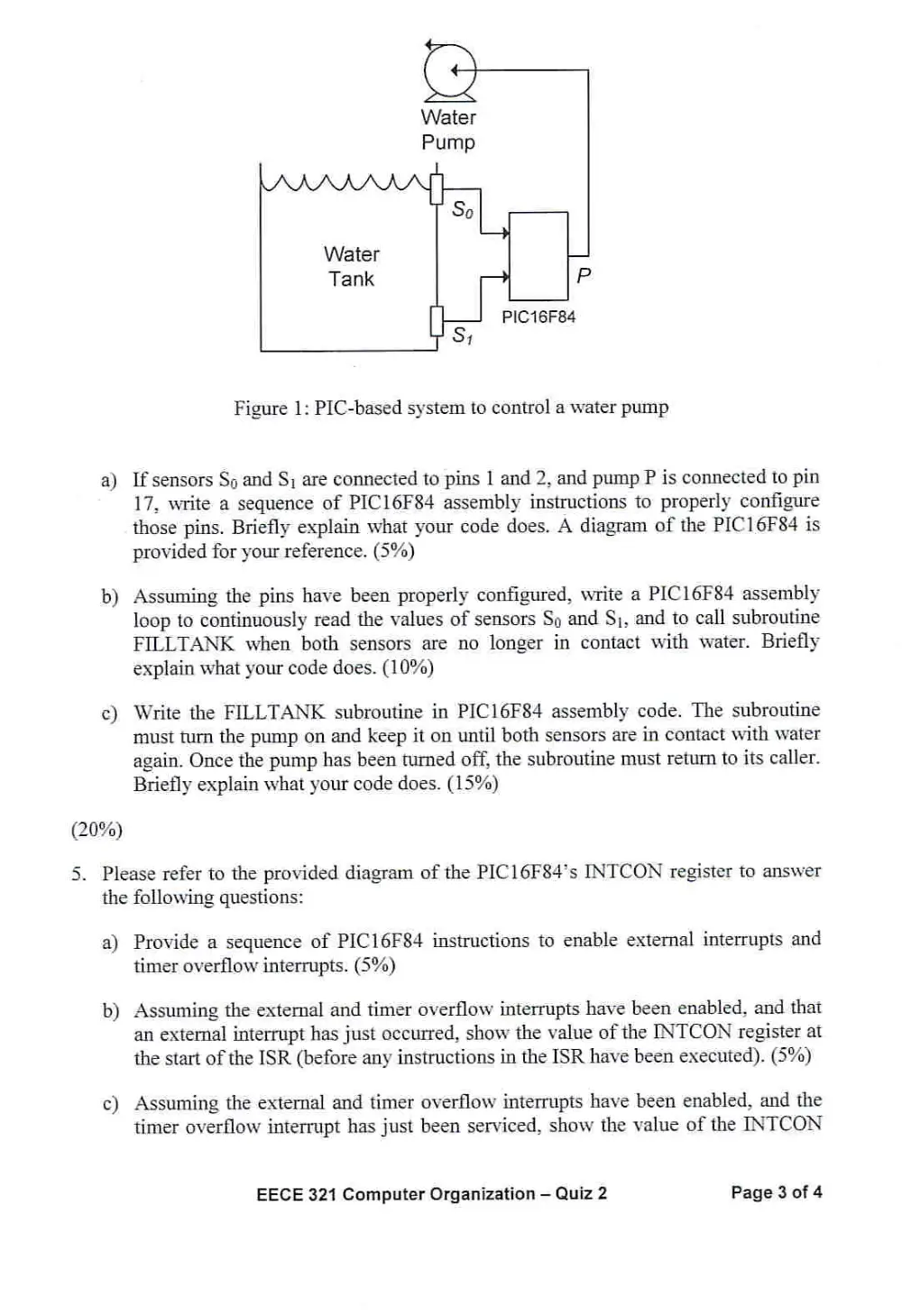
4. You have been asked to design a PIC-based system for controlling a water pump.
Figure 1 shows a block diagram of the system. Two sensors. Sp and S;, are used to
sense the water level. If a sensor is in contact with water its value is HIGH; otherwise
it is LOW. Your controller must monitor the water level continuously. Once sensor S;
is no longer in contact with water, the controller must turn the water pump on. The
pump must remain ON until both sensors are in contact with water again. The pump
turns on when the value on signal P is HIGH; otherwise the pump is off.
EECE 321 Computer Organization — Quiz 2 Page 2 of 4
a)
b)
(20%)
PIC16F84
Figure 1: PIC-based system to control a water pump
If sensors So and S; are connected to pins | and 2, and pump P is connected to pin
17, write a sequence of PICI6F84 assembly instructions to properly configure
those pins. Briefly explain what your code does. A diagram of the PIC16F84 is
provided for your reference. (5%)
Assuming the pins have been properly configured, write a PIC]16F84 assembly
loop to continuously read the values of sensors Sp and $), and to call subroutine
FILLTANK when both sensors are no longer in contact with water. Briefly
explain what your code does. (10%)
Write the FILLTANK subroutine in PIC16F84 assembly code. The subroutine
must turn the pump on and keep it on until both sensors are in contact with water
again. Once the pump has been turned off, the subroutine must return to its caller.
Briefly explain what your code does. (15%)
5. Please refer to the provided diagram of the PIC16F84’s INTCON register to answer
the following questions:
a)
b)
Provide a sequence of PIC16F84 instructions to enable external interrupts and
timer overflow interrupts. (5%)
Assuming the external and timer overflow interrupts have been enabled, and that
an external interrupt has just occurred, show the value of the INTCON register at
the start of the ISR (before any instructions in the ISR have been executed). (5%)
Assuming the external and timer overflow interrupts have been enabled, and the
timer overflow interrupt has just been serviced, show the value of the INTCON
EECE 321 Computer Organization — Quiz 2 Page 3 of 4
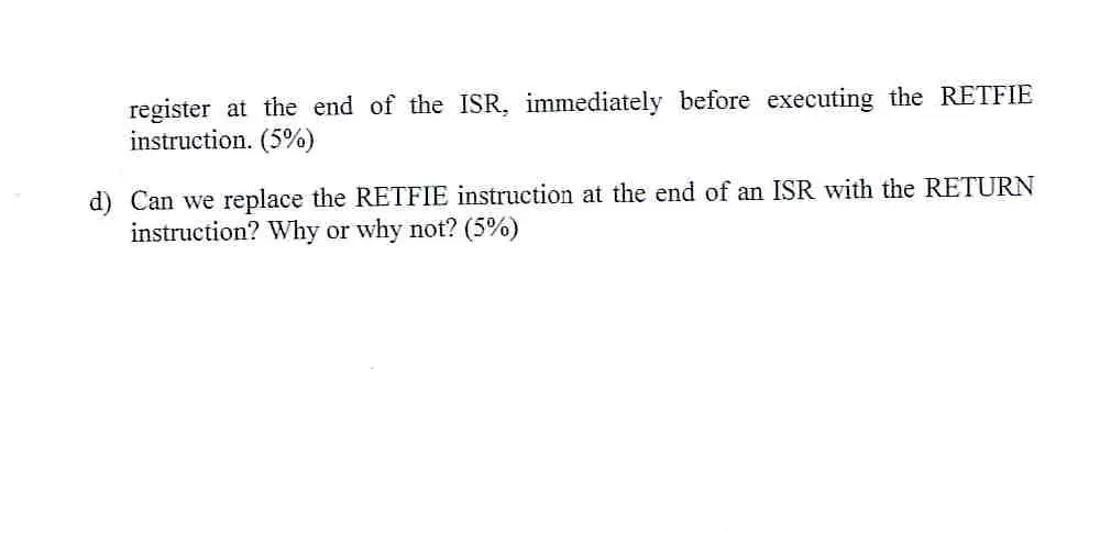
register at the end of the ISR. immediately before executing the RETFIE
instruction. (5%)
d) Can we replace the RETFIE instruction at the end of an ISR with the RETURN
instruction? Why or why not? (5%)
(20%)
4.
Orv
eit a
= \
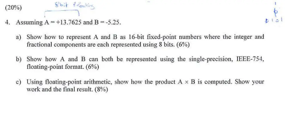
Assuming A = +13.7625 and B =-5.25.
a)
b)
Show how to represent A and B as 16-bit fixed-point numbers where the integer and
fractional components are each represented using 8 bits. (6%)
Show how A and B can both be represented using the single-precision, [EEE-754,
floating-point format. (6%)
Using floating-point arithmetic, show how the product A x B is computed. Show your
work and the final result. (8%)