
EECE 380 Notes Chapter 3.2, Fall 2011
American University of Beirut · Engineering Electromagnetics · 18 pages

Showing the first 10 of 18 pages. Download the PDF to see all of it.
More EECE 380 files
- Notes Chap 3.1 · Fall 2011NotesView
- Notes · Spring 2008NotesView
- Homework 6 Solution · Fall 2016Homework · with solutionView
- Other Formula Sheet 2 · Fall 2014FileView
- Exam 1 with Solution · Spring 2014Exam · with solutionView
- Exam 2 with Solutions · Spring 2014Exam · with solutionView
- Exam 1 · Spring 2013ExamView
- Exam 1 With Answers · Fall 2013Exam · with solutionView
Show the text of this notes
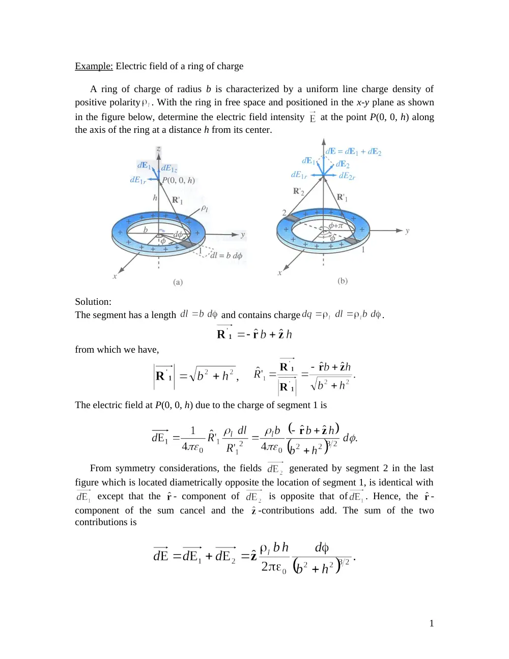
Example: Electric field of a ring of charge
A ring of charge of radius b is characterized by a uniform line charge density of
positive polarity
. With the ring in free space and positioned in the x-y plane as shown
in the figure below, determine the electric field intensity
at the point P(0, 0, h) along
the axis of the ring at a distance h from its center.
Solution:
The segment has a length
and contains charge
.
from which we have,
The electric field at P(0, 0, h) due to the charge of segment 1 is
From symmetry considerations, the fields
generated by segment 2 in the last
figure which is located diametrically opposite the location of segment 1, is identical with
except that the - component of
is opposite that of
. Hence, the -
component of the sum cancel and the
-contributions add. The sum of the two
contributions is
1
so,
where
.
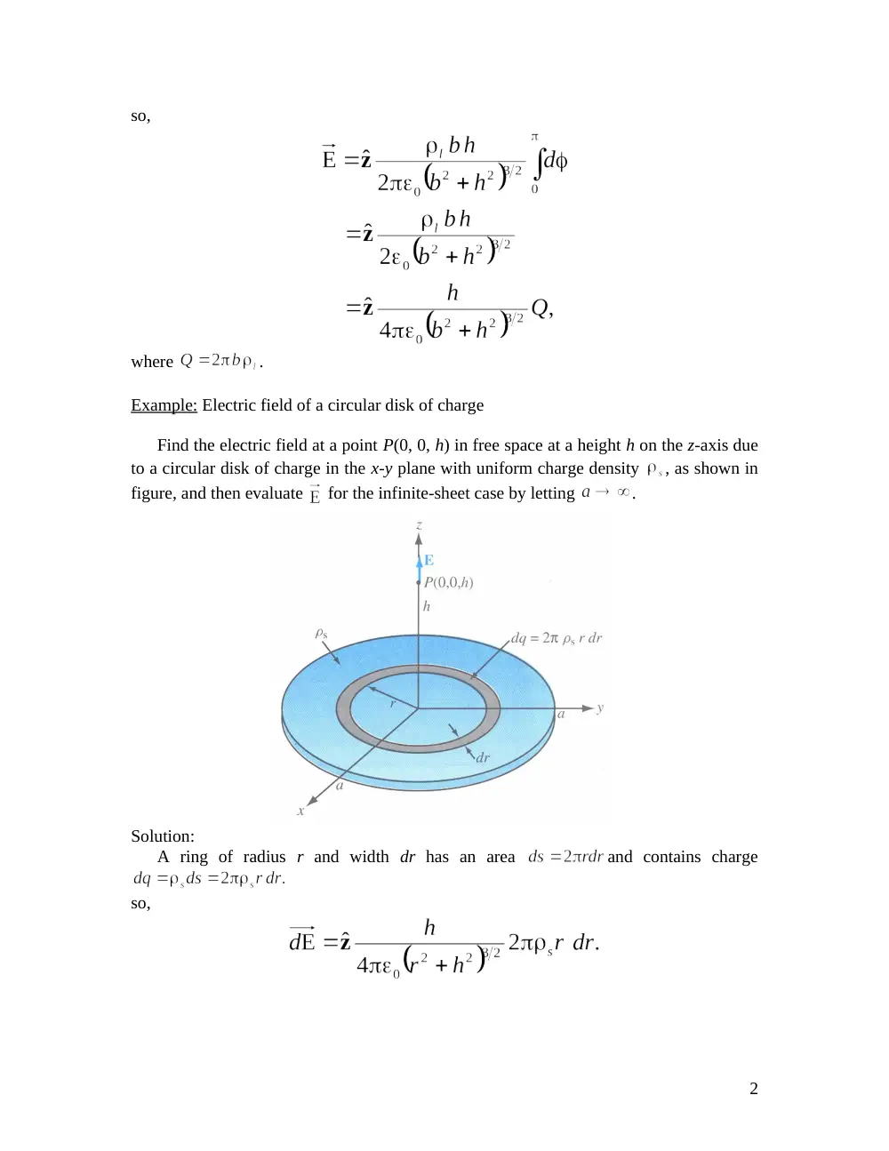
Example: Electric field of a circular disk of charge
Find the electric field at a point P(0, 0, h) in free space at a height h on the z-axis due
to a circular disk of charge in the x-y plane with uniform charge density
, as shown in
figure, and then evaluate
for the infinite-sheet case by letting
.
Solution:
A ring of radius r and width dr has an area
and contains charge
so,
2
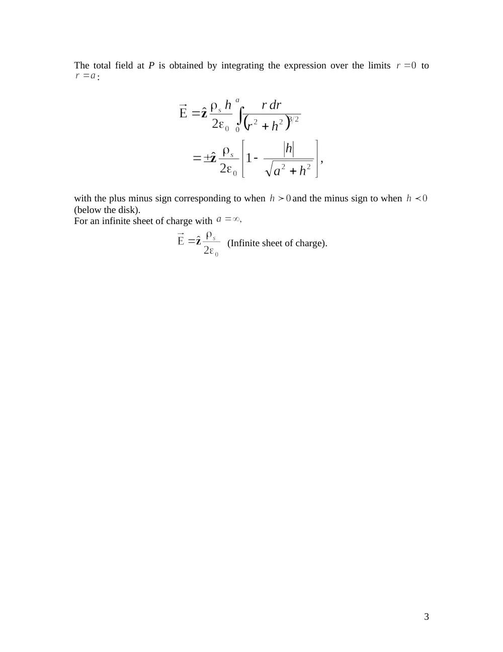
The total field at P is obtained by integrating the expression over the limits
to
:
with the plus minus sign corresponding to when
and the minus sign to when
(below the disk).
For an infinite sheet of charge with
(Infinite sheet of charge).
3
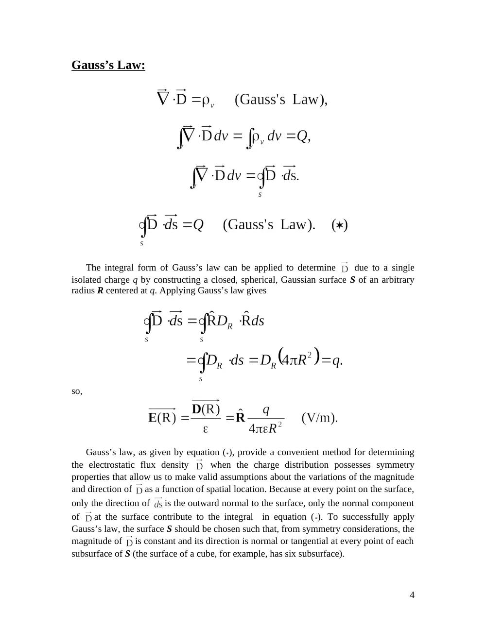
Gauss’s Law:
The integral form of Gauss’s law can be applied to determine
due to a single
isolated charge q by constructing a closed, spherical, Gaussian surface S of an arbitrary
radius R centered at q. Applying Gauss’s law gives
so,
Gauss’s law, as given by equation (*), provide a convenient method for determining
the electrostatic flux density
when the charge distribution possesses symmetry
properties that allow us to make valid assumptions about the variations of the magnitude
and direction of
as a function of spatial location. Because at every point on the surface,
only the direction of
is the outward normal to the surface, only the normal component
of
at the surface contribute to the integral in equation (*). To successfully apply
Gauss’s law, the surface S should be chosen such that, from symmetry considerations, the
magnitude of
is constant and its direction is normal or tangential at every point of each
subsurface of S (the surface of a cube, for example, has six subsurface).
4
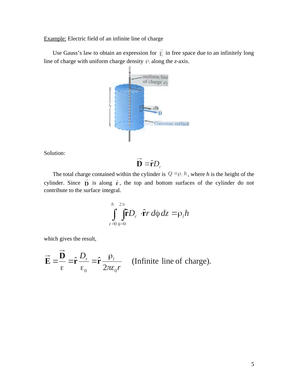
Example: Electric field of an infinite line of charge
Use Gauss’s law to obtain an expression for
in free space due to an infinitely long
line of charge with uniform charge density
along the z-axis.
Solution:
The total charge contained within the cylinder is
, where h is the height of the
cylinder. Since
is along , the top and bottom surfaces of the cylinder do not
contribute to the surface integral.
which gives the result,
5
Electric potential as a function of electric field
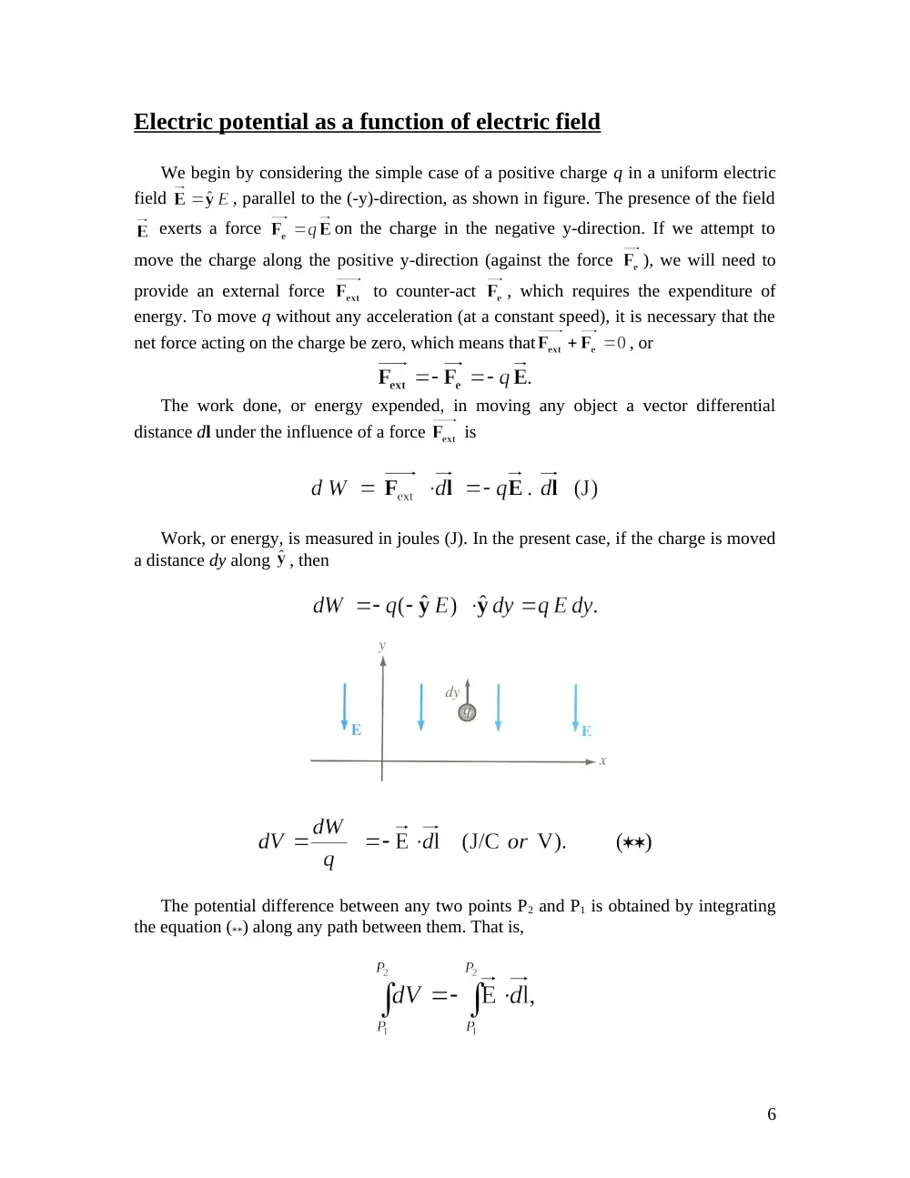
We begin by considering the simple case of a positive charge q in a uniform electric
field
, parallel to the (-y)-direction, as shown in figure. The presence of the field
exerts a force
on the charge in the negative y-direction. If we attempt to
move the charge along the positive y-direction (against the force
), we will need to
provide an external force
to counter-act
, which requires the expenditure of
energy. To move q without any acceleration (at a constant speed), it is necessary that the
net force acting on the charge be zero, which means that
, or
The work done, or energy expended, in moving any object a vector differential
distance dl under the influence of a force
is
Work, or energy, is measured in joules (J). In the present case, if the charge is moved
a distance dy along
, then
The potential difference between any two points P2 and P1 is obtained by integrating
the equation (**) along any path between them. That is,
6
or,
Usually, the reference-potential point is chosen to be at infinity. That is, in equation
(***) we assume that
when P1 is at infinity, and therefore the electric potential
at
any point P is given by
Electric potential due to point charges
For a point charge q located at the origin of a spherical coordinate system, the electric
field at a distance R is given by
Hence, we will conveniently choose the path to be along the radial direction , in which
case
and
If the charge q is at a location other than the origin, specified by a source position
vector
, then V at observation position vector
becomes
where
is the distance between the observation point and the location of the
charge q. The principle of superposition that we applied previously to the electric field
also applies to the electric potential V. Hence, for N discrete point charges q1, q2,..., qN
having position vectors
,
, . . . ,
, the electric potential is
7
Electric potential due to continuous distributions
Based on previous analysis:
Electric field as a function of electric potential
From mathematical reasoning any vector whose curl = 0 (
) can be
expressed as
. The minus sign is to indicate that the work done to move q is
against the field
.
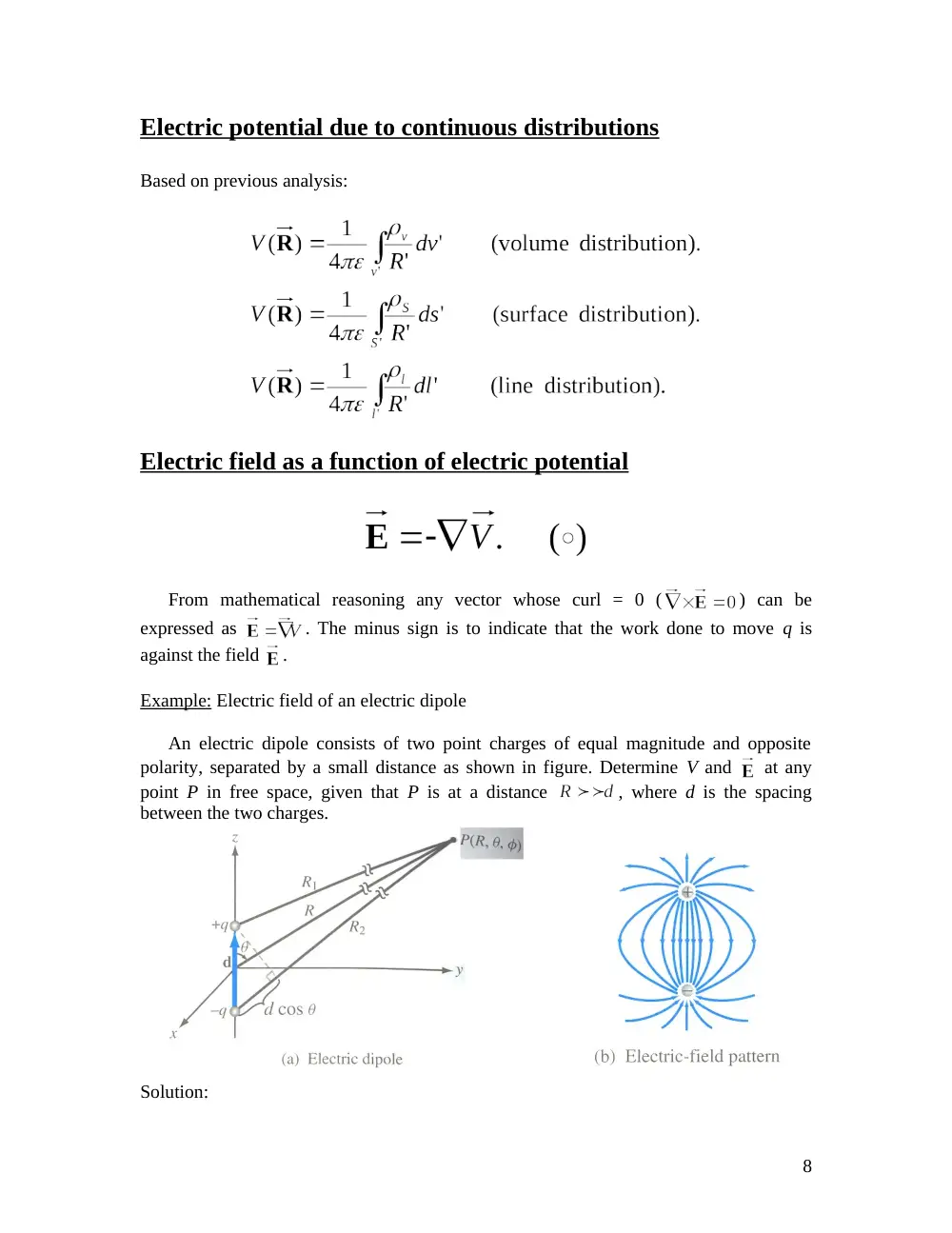
Example: Electric field of an electric dipole
An electric dipole consists of two point charges of equal magnitude and opposite
polarity, separated by a small distance as shown in figure. Determine V and
at any
point P in free space, given that P is at a distance
, where d is the spacing
between the two charges.
Solution:
8
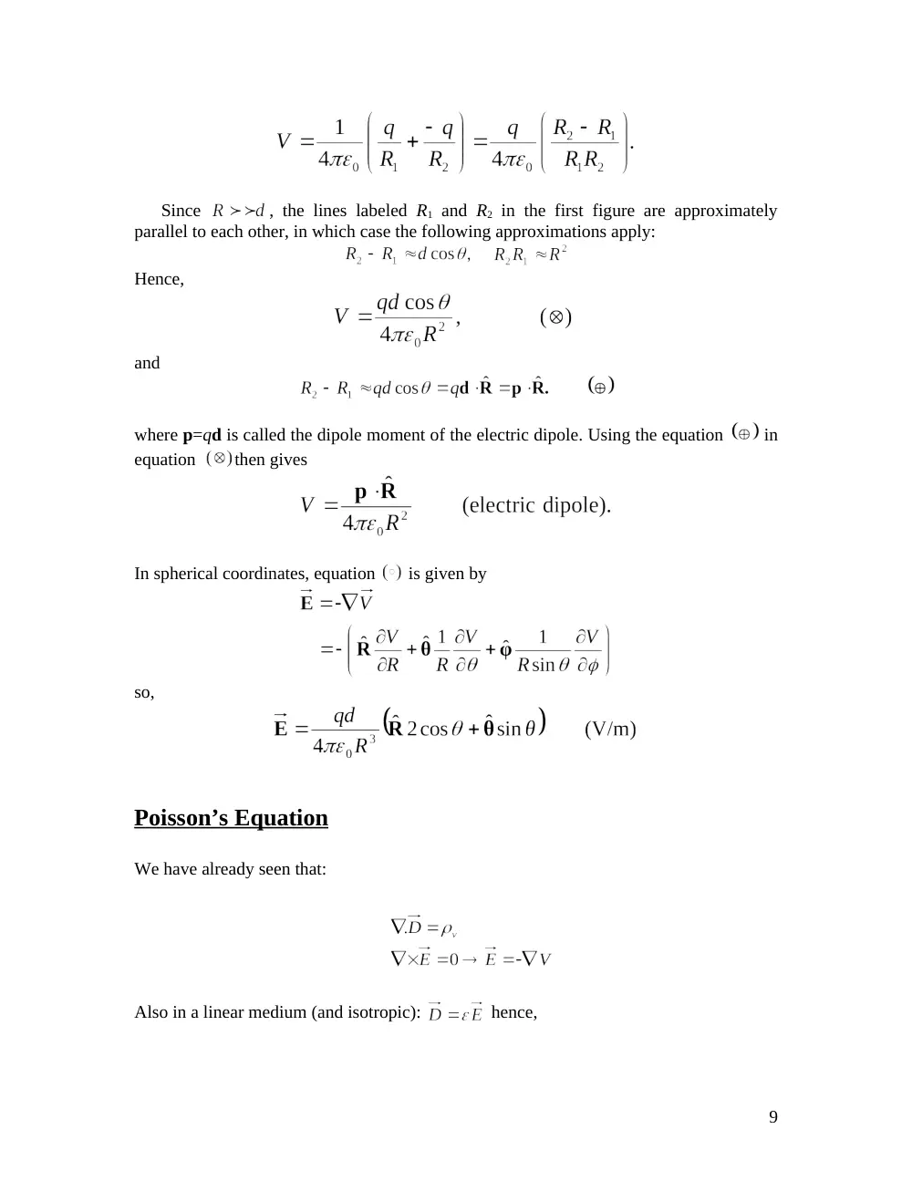
Since
, the lines labeled R1 and R2 in the first figure are approximately
parallel to each other, in which case the following approximations apply:
Hence,
and
where p=qd is called the dipole moment of the electric dipole. Using the equation
in
equation
then gives
In spherical coordinates, equation
is given by
so,
Poisson’s Equation
We have already seen that:
Also in a linear medium (and isotropic):
hence,
9
or
Where
can be a function or position. For a simple medium (homogeneous)
is a
constant:
(del square) is the Laplacian operator –‘it is the divergence of the gradient of-‘
is called Poisson’s equations.
For a volume v’ containing a volume density distribution
, the solution for V derived
previously and expressed as
satisfies Poisson’s equation. If the medium under consideration contains no free charges,
Poisson’s equation reduces to
In Cartesian coordinates:
And this becomes:
(V/m2)
In cylindrical coordinates:
In spherical coordinates:
Remark: 3-D solution is a difficult task; normally 2-D and 1-D are sought.
10
In mediums where
Laplace’s equation
3.11.2 Boundary-Value Problems in Cartesian coordinates
Example 1:
Two large // conducting plates are separated by a distance d and maintained at a potential
0 and V0, as shown.
The region between the plates is filled with a
continuous distribution of electrons having a
volume density of charges
assuming negligible fringing effect
at the edges, determine:
a- The potential at any point between the plates.
b- The surface charge densities on the plates.
Solution:
a- Here the equation is:
Integrating twice:
The boundary conditions on the two conducting plates:
At y = 0 we have V = 0 = C2
At y = d we have V = Vo =
Substituting C1 and C2 in V(y):
11
And
12
b- At y = 0 (lower plate)
At the upper plate: y = d
Here,
and it is no longer meaningful to compute the capacitance.
3.11.3 Boundary – value problems in cylindrical coordinates.
Here:
In situations where there is cylindrical symmetry:
and “y” the lengthwise
dimension is very large compared to the radius “r”
so what’s left is:
And “V” is a function of r only. The solution is:
Where C1 and C2 are to be determined from boundary conditions;
If the problem is such that electric potential changes only in the circumferential
direction and not in “r-” and “Z-” directions; we have:
Example:
Two infinite insulation planes maintained at potentials 0 and V0 from a wedge-shaped
configuration. Determine the potential distributions for the regions:
a-
b-
13
Here we have
and
since the region at V = 0 is excluded:
;
V depends only on
and can be found by double integrating.
K1 and K2 are to be determined from boundary conditions.
a-
b-
3.11.4 B.V.P in spherical coordinates.
See Example 3-23 (self-reading).
Conductors
The drift velocity
of electrons in a conducting material is related to the externally
applied electric filed
through
14
where
is a material property call the electron mobility with units of (m2/V.s). In a
semiconductor, current flow is due to the movement of both electrons and holes, and
since holes are positive-charge carriers, the hole drift velocity
is in the same direction
as
,
where
is the hole mobility.
The current density in a medium containing a volume density
of charges moving with
a velocity
is
. Thus, the total conduction current density is
or
where
and
, with Ne and Nh being the number of free electrons
and the number of free holes per unit volume, and
is the absolute charge
of a single hole or electron. The quantity inside the parentheses is defined as the
conductivity of the material,
. Thus,
so,
This equation is called the point form of Ohm’s law. Note that, in a perfect dielectric with
regardless of
, and in a perfect conductor with
regardless of
. That is,
Resistance
15
Example: Conductance of coaxial cable
The radii of the inner and outer
conductors of a coaxial cable of length l
are a and b respectively. The insulation
material has conductivity
. Obtain an
expression for G’, the conductance per
unit length of the insulation layer.
Solution:
Let I be the total current flowing from the inner conductor to the outer conductor
through the insulation material. At any radial distance r from the axis of the center
conductor, the area through which the current flows is
. Hence,
and from
In a resistor, the current flows from higher electric potential to lower potential.
Hence, if
is the -direction, the inner conductor must be at a higher potential than the
outer conductor. Accordingly, the voltage difference between the conductors is
The conductance per unit length is then
Dielectrics
16
In a dielectric, an externally applied field
cannot effect mass migration of
charges since none are able to move freely, but it can polarize the atoms or molecules in
the material by distorting the center of the cloud and the location of the nucleus.
In the absence of
an external electric
field
, the center
of the electron cloud is
co-located with the
center of the nucleus,
but when a field is
applied, the two
centers are separated
by a distance d.
The induced electric field, called a polarization field, is weaker than and opposite in
direction to
. Consequently, the net electric field present in the dielectric material is
smaller than
.
Whereas
and
are related by
in free space, the presence of these microscopic
dipoles in a dielectric material alters that relationship in that material to
where
, called the electric polarization field, accounts for the polarization properties of
the material. A dielectric medium is said to be linear if the magnitude of the induced
polarization field is directly proportional to the magnitude of
, and it is said to be
isotropic if the polarization field and
are in the same direction.
A medium is said to be homogenous if its constitutive parameters (
) are
constant throughout the medium.
where
is called the electric susceptibility of the material. Thus we have
which defines the permittivity of the material as
17
In reality, if
exceeds a certain critical value, known as the dielectric strength of the
material, it will free the electrons completely from the molecules and cause them to
accelerate through the material in the form of a conducting current. When this happens,
sparking can occur, and the dielectric material can sustain permanent damage due to
electron collision with the molecular structure. This abrupt change in behavior is called
dielectric breakdown.
18