
EECE 471 Final, Fall 2005
American University of Beirut · Fundamentals of Power Systems Analysis · 4 pages · Prof. Sami Karaki
More EECE 471 files
- Final · Summer 2010Final examView
- Final Solution · Summer 2010Final exam · with solutionView
- Final · Fall 2008Final examView
- Final Solution · Fall 2008Final exam · with solutionView
- Final · Fall 2007Final examView
- Final Solution · Fall 2007Final exam · with solutionView
- Final Solution · Fall 2005Final exam · with solutionView
- Final Solution · Fall 2003Final exam · with solutionView
Show the text of this final exam
EECE 471E
FINAL EXAM - FALL 2005/ 2006
1/ 10
S. KARAKI
AMERICAN UNIVERSITY OF BEIRUT
FALL 2005/ 2006
FACULTY OF ENGINEERING AND ARCHITECTURE
FINAL EXAM
FUNDAMENTALS OF POWER SYSTEMS ANALYSIS (EECE 471E)
CLOSED BOOK (3 HOURS)
January 28, 2006
PROGRAMMABLE CALCULATORS ARE NOT ALLOWED.
THIS QUESTION SHEET MUST BE RETURNED WITH THE ANSWER BOOKLET.
BRIEFLY EXPLAIN CALCULATIONS BY SHOWING FORMULAE USED OR OTHERWISE AS NEEDED.
NAME: _________________________
ID#: _________________________
1.
In this exam the operational analysis of the transmission system shown in Fig. 1 is
considered. In this first problem the power flow problem of the transmission system is
solved, however, partially due to time limitation. In the second problem the economic load
dispatch (ELD) of this system is formulated and solved with and without losses. And in the
third part the fault level analysis of the transmission system is carried out for a line-to-line
and a line-to-ground fault. Except for the simple calculation of the line and other system
parameters in per unit in Part a) and the generation limits in this problem, the three
problems are essentially independent. The practice in the utility has been to allow for a
maximum current density of 2 A/mm2 for thermal rating and the conductors are 2×200 mm2
per phase. The transmission voltage is 220 kV and the line length is 320 km. The
transmission lines specific series impedance is given as rl + jxl= 0.08 + j0.35 Ω/km. Its
shunt admittance is given by ys= j3.2 µS/km. The transformers have a rating of 300 MVA
each and a leakage reactance of 10% on rating. Furthermore, the following additional data
is known about the system:
Generator G1: 300 MVA, PF= 0.85,13 kV, XS= 125%.
Generator G2: 80 MVA, PF= 0.85,11 kV, XS= 100%.
Load at node 1: 20 + j10 MVA
Load at node 4: 180 + j80 MVA
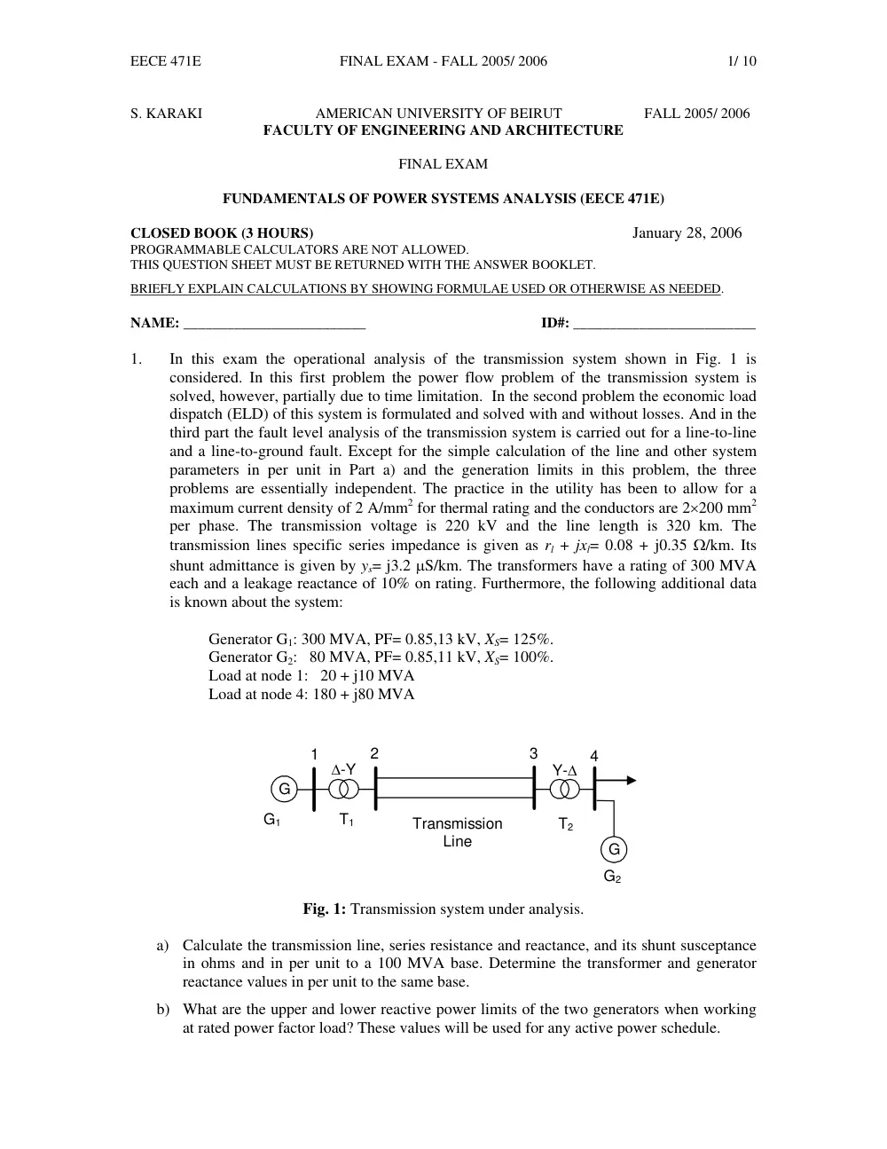
∆-Y
Transmission
Line
G
Y-∆
1
T1
T2
2
3
4
G
G1
G2
Fig. 1: Transmission system under analysis.
a) Calculate the transmission line, series resistance and reactance, and its shunt susceptance
in ohms and in per unit to a 100 MVA base. Determine the transformer and generator
reactance values in per unit to the same base.
b) What are the upper and lower reactive power limits of the two generators when working
at rated power factor load? These values will be used for any active power schedule.
EECE 471E
FINAL EXAM - FALL 2005/ 2006
2/ 10
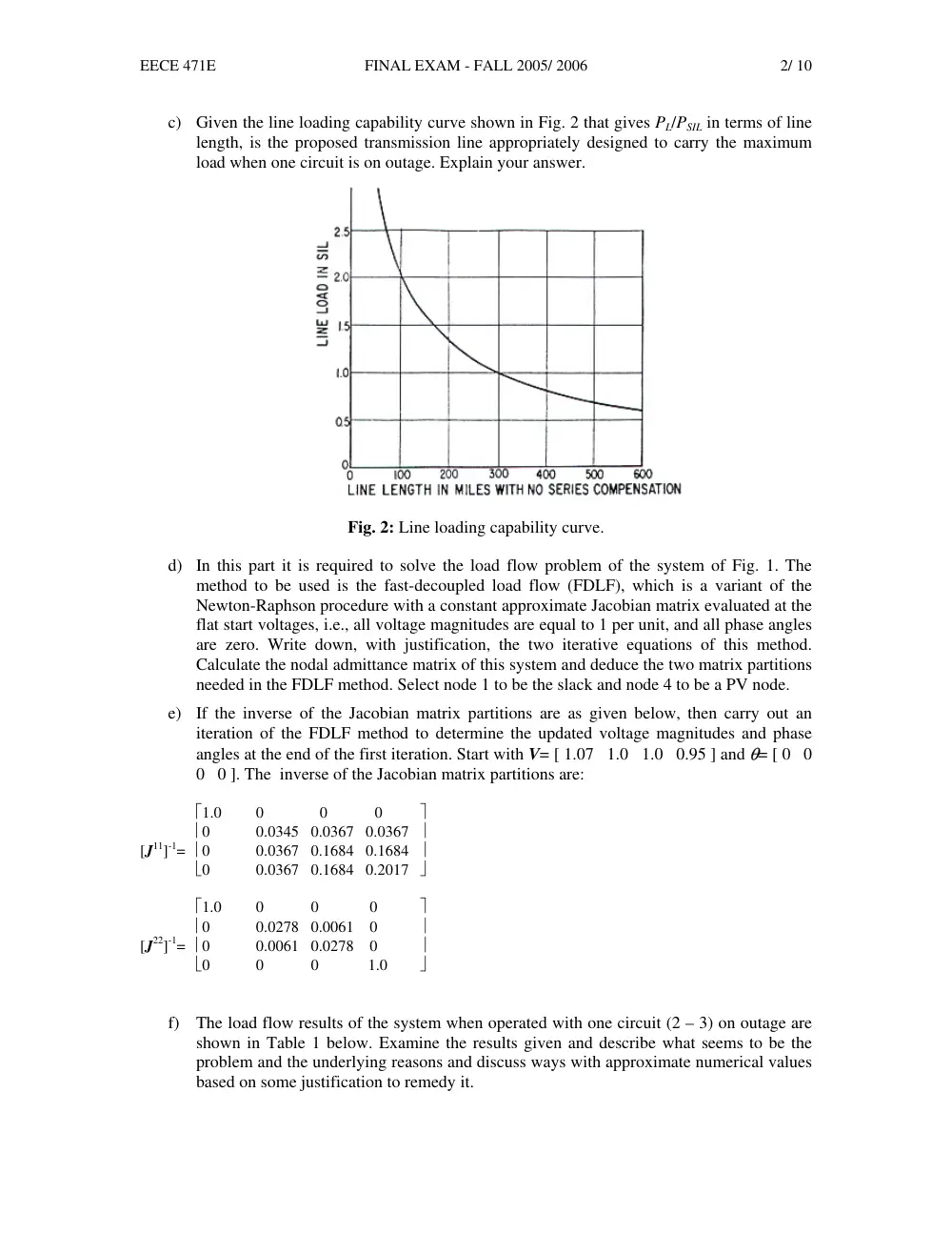
c) Given the line loading capability curve shown in Fig. 2 that gives PL/PSIL in terms of line
length, is the proposed transmission line appropriately designed to carry the maximum
load when one circuit is on outage. Explain your answer.
Fig. 2: Line loading capability curve.
d) In this part it is required to solve the load flow problem of the system of Fig. 1. The
method to be used is the fast-decoupled load flow (FDLF), which is a variant of the
Newton-Raphson procedure with a constant approximate Jacobian matrix evaluated at the
flat start voltages, i.e., all voltage magnitudes are equal to 1 per unit, and all phase angles
are zero. Write down, with justification, the two iterative equations of this method.
Calculate the nodal admittance matrix of this system and deduce the two matrix partitions
needed in the FDLF method. Select node 1 to be the slack and node 4 to be a PV node.
e) If the inverse of the Jacobian matrix partitions are as given below, then carry out an
iteration of the FDLF method to determine the updated voltage magnitudes and phase
angles at the end of the first iteration. Start with V= [ 1.07 1.0 1.0 0.95 ] and θ= [ 0 0
0 0 ]. The inverse of the Jacobian matrix partitions are:
⎡1.0
0
0 0
⎤
⎢0
0.0345 0.0367 0.0367 ⎥
[J11]-1= ⎢0
0.0367 0.1684 0.1684 ⎥
⎣0
0.0367 0.1684 0.2017 ⎦
⎡1.0
0 0 0
⎤
⎢0
0.0278 0.0061 0
⎥
[J22]-1= ⎢0
0.0061 0.0278 0
⎥
⎣0
0 0
1.0 ⎦
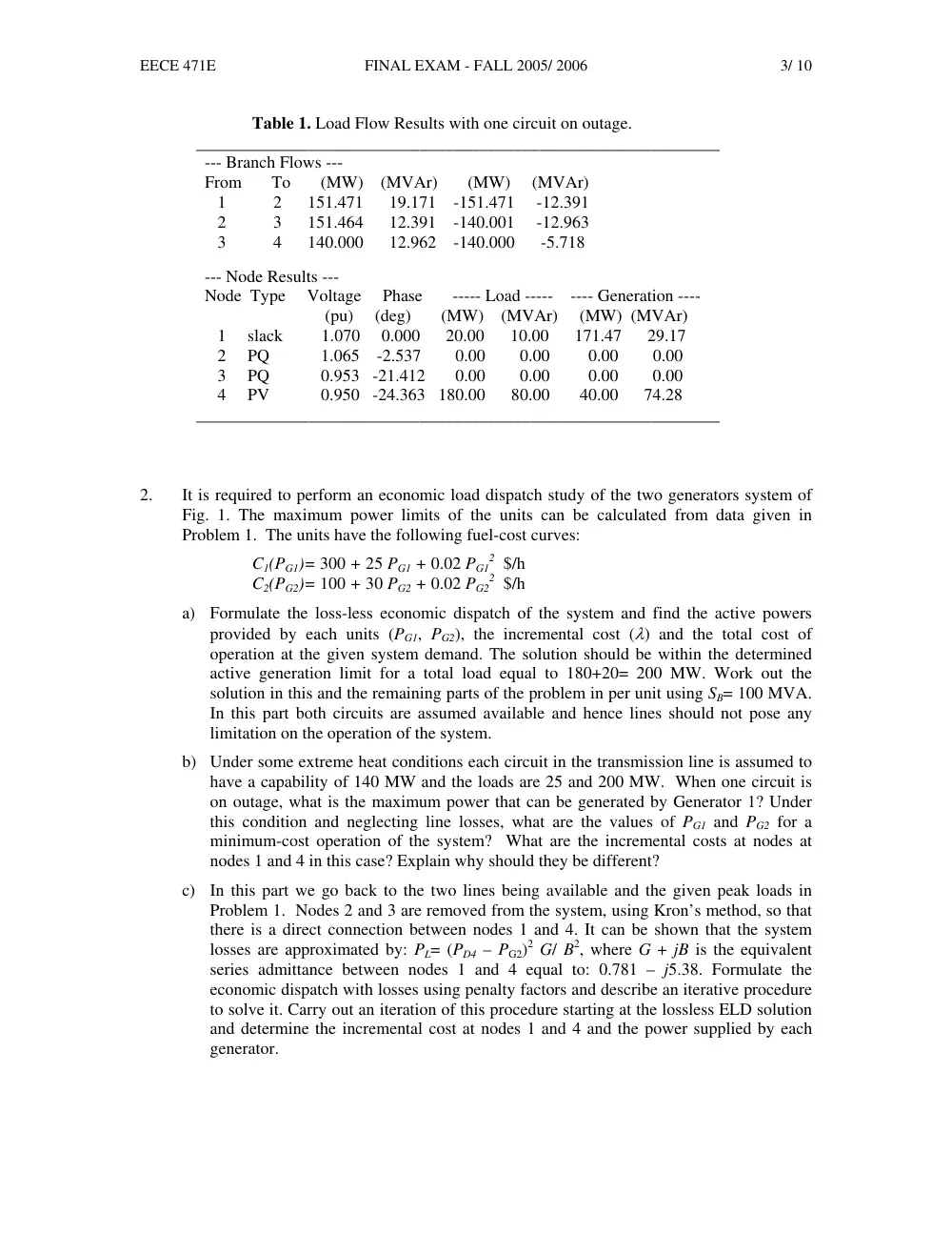
f) The load flow results of the system when operated with one circuit (2 – 3) on outage are
shown in Table 1 below. Examine the results given and describe what seems to be the
problem and the underlying reasons and discuss ways with approximate numerical values
based on some justification to remedy it.
EECE 471E
FINAL EXAM - FALL 2005/ 2006
3/ 10
Table 1. Load Flow Results with one circuit on outage.
_____________________________________________________________
--- Branch Flows ---
From To (MW) (MVAr) (MW) (MVAr)
1 2 151.471 19.171 -151.471 -12.391
2 3 151.464 12.391 -140.001 -12.963
3 4 140.000 12.962 -140.000 -5.718
--- Node Results ---
Node Type Voltage Phase ----- Load ----- ---- Generation ----
(pu) (deg) (MW) (MVAr) (MW) (MVAr)
1 slack 1.070 0.000 20.00 10.00 171.47 29.17
2 PQ 1.065 -2.537 0.00 0.00 0.00 0.00
3 PQ 0.953 -21.412 0.00 0.00 0.00 0.00
4 PV 0.950 -24.363 180.00 80.00 40.00 74.28
_____________________________________________________________
2.
It is required to perform an economic load dispatch study of the two generators system of
Fig. 1. The maximum power limits of the units can be calculated from data given in
Problem 1. The units have the following fuel-cost curves:
C1(PG1)= 300 + 25 PG1 + 0.02 PG1
2 $/h
C2(PG2)= 100 + 30 PG2 + 0.02 PG2
2 $/h
a) Formulate the loss-less economic dispatch of the system and find the active powers
provided by each units (PG1, PG2), the incremental cost (λ) and the total cost of
operation at the given system demand. The solution should be within the determined
active generation limit for a total load equal to 180+20= 200 MW. Work out the
solution in this and the remaining parts of the problem in per unit using SB= 100 MVA.
In this part both circuits are assumed available and hence lines should not pose any
limitation on the operation of the system.
b) Under some extreme heat conditions each circuit in the transmission line is assumed to
have a capability of 140 MW and the loads are 25 and 200 MW. When one circuit is
on outage, what is the maximum power that can be generated by Generator 1? Under
this condition and neglecting line losses, what are the values of PG1 and PG2 for a
minimum-cost operation of the system? What are the incremental costs at nodes at
nodes 1 and 4 in this case? Explain why should they be different?
c) In this part we go back to the two lines being available and the given peak loads in
Problem 1. Nodes 2 and 3 are removed from the system, using Kron’s method, so that
there is a direct connection between nodes 1 and 4. It can be shown that the system
losses are approximated by: PL= (PD4 – PG2)2 G/ B2, where G + jB is the equivalent
series admittance between nodes 1 and 4 equal to: 0.781 – j5.38. Formulate the
economic dispatch with losses using penalty factors and describe an iterative procedure
to solve it. Carry out an iteration of this procedure starting at the lossless ELD solution
and determine the incremental cost at nodes 1 and 4 and the power supplied by each
generator.
EECE 471E
FINAL EXAM - FALL 2005/ 2006
4/ 10
3.
In this third problem it is required to carry out a fault level analysis of the system presented
in Fig. 1. In addition to the given data the transient, sub-transient and leakage reactances
are given as 30%, 20% and 6% on generator rating. Neglect the transmission line resistance
in this problem. The generators are Y-connected with the neutral solidly grounded and the
Y-sides of the transformers are also solidly grounded.
a) Draw the positive, negative and zero sequence networks of the system with all
reactance values given in per unit on 100 MVA base.
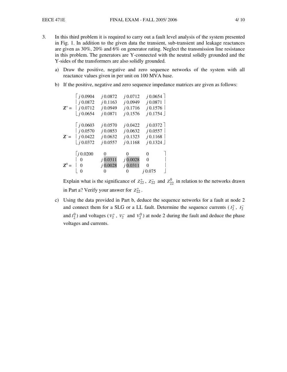
b) If the positive, negative and zero sequence impedance matrices are given as follows:
⎡ j 0.0904 j 0.0872 j 0.0712 j 0.0654 ⎤
⎢ j 0.0872 j 0.1163 j 0.0949 j 0.0871 ⎥
Z+ = ⎢ j 0.0712 j 0.0949 j 0.1716 j 0.1576 ⎥
⎣ j 0.0654 j 0.0871 j 0.1576 j 0.1754 ⎦
⎡ j 0.0603 j 0.0570 j 0.0422 j 0.0372 ⎤
⎢ j 0.0570 j 0.0853 j 0.0632 j 0.0557 ⎥
Z– = ⎢ j 0.0422 j 0.0632 j 0.1323 j 0.1168 ⎥
⎣ j 0.0372 j 0.0557 j 0.1168 j 0.1324 ⎦
⎡j 0.0200 0 0 0
⎤
⎢ 0 j 0.0311 j 0.0028 0
⎥
Z0 = ⎢ 0 j 0.0028 j 0.0311 0
⎥
⎣ 0 0 0 j 0.075 ⎦
Explain what is the significance of
Z+22
,
Z−22
and
0
Z22
in relation to the networks drawn
in Part a? Verify your answer for
Z+22
.
c) Using the data provided in Part b, deduce the sequence networks for a fault at node 2
and connect them for a SLG or a LL fault. Determine the sequence currents (
+2
I ,
−2
I
and 0
2
I ) and voltages (
+2
V ,
−2
V and
0
2
V ) at node 2 during the fault and deduce the phase
voltages and currents.