
EECE 471 Final, Fall 2008
American University of Beirut · Fundamentals of Power Systems Analysis · 2 pages · Prof. Sami Karaki
More EECE 471 files
- Final · Summer 2010Final examView
- Final Solution · Summer 2010Final exam · with solutionView
- Final Solution · Fall 2008Final exam · with solutionView
- Final · Fall 2007Final examView
- Final Solution · Fall 2007Final exam · with solutionView
- Final · Fall 2005Final examView
- Final Solution · Fall 2005Final exam · with solutionView
- Final Solution · Fall 2003Final exam · with solutionView
Show the text of this final exam
EECE 471
FINAL EXAM - FALL 2008/ 2009
1/ 6
S. KARAKI
AMERICAN UNIVERSITY OF BEIRUT
FALL 2008/ 2009
FACULTY OF ENGINEERING AND ARCHITECTURE
FINAL EXAM
FUNDAMENTALS OF POWER SYSTEMS ANALYSIS (EECE 471)
CLOSED BOOK (2.5 HOURS)
February 3, 2009
PROGRAMMABLE CALCULATORS ARE NOT ALLOWED.
THIS QUESTION SHEET MUST BE RETURNED WITH THE ANSWER BOOKLET.
BRIEFLY EXPLAIN CALCULATIONS BY SHOWING FORMULAE USED.
NAME: _________________________
ID#: _________________________
1.
It is required to perform an economic load dispatch study on a system of two generators
supplying a load of PD= 200 MW and connected by a transmission line and the system
losses are approximated by: PL= 5× 10⁻⁴× (PD – PG2)2. The maximum and minimum active
power limits of the units are given as: 0 ≤ PG1 ≤ 160 and 0 ≤ PG2 ≤ 85. The units have the
following fuel-cost curves:
C1(PG1)= 250 + 30 PG1 + 0.005 PG12 $/h
C2(PG2)= 100 + 28 PG2 + 0.02 PG22 $/h
a)Write the objective function and the constraints of the economic dispatch of the system
with losses and use the method of Lagrange to write the necessary optimality
conditions defining the saddle point (i.e. the optimum point).
b)Describe an iterative procedure based on penalty factors to solve the optimality
conditions developed above and determine the active powers provided by each units
(PG1, PG2), the incremental cost (λ) and the total cost of operation at the given system
demand. Carry out an iteration of this procedure starting at the lossless ELD solution
and determine the incremental cost at nodes 1 and 2 and the power supplied by each
generator at the end of the iteration.
2.
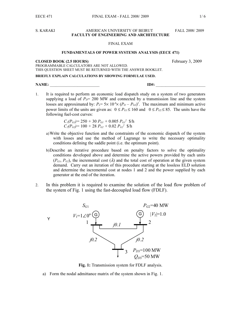
In this problem it is required to examine the solution of the load flow problem of
the system of Fig. 1 using the fast-decoupled load flow (FDLF).
V1=1∠0°
|V2|=1.0
PG2=40 MW
G
SG1
G
1
2
3
PD3=100 MW
QD3=50 MW
j0.2
j0.2
j0.1
Y
Fig. 1: Transmission system for FDLF analysis.
a) Form the nodal admittance matrix of the system shown in Fig. 1.
EECE 471
FINAL EXAM - FALL 2008/ 2009
2/ 6
b) Identify the type of busbars and the unknown variables that we are solving for in the
system shown in Figure 1. Write the active and reactive mismatch equations to be solved
in order to determine these variables.
c) Briefly describe the main characteristics of the FDLF method and how it can be derived
from the Newton-Raphson method. Write the iterative FDLF equations showing the
elements of the approximate Jacobian matrices for the problem being solved.
d) Carry out an iteration of the FDLF method for the equations in Part c from a set of
appropriate starting values.
3.
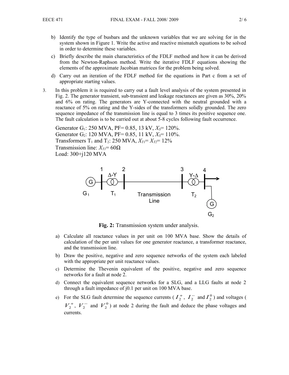
In this problem it is required to carry out a fault level analysis of the system presented in
Fig. 2. The generator transient, sub-transient and leakage reactances are given as 30%, 20%
and 6% on rating. The generators are Y-connected with the neutral grounded with a
reactance of 5% on rating and the Y-sides of the transformers solidly grounded. The zero
sequence impedance of the transmission line is equal to 3 times its positive sequence one.
The fault calculation is to be carried out at about 5-8 cycles following fault occurrence.
Generator G1: 250 MVA, PF= 0.85, 13 kV, XS= 120%.
Generator G2: 120 MVA, PF= 0.85, 11 kV, XS= 110%.
Transformers T1 and T2: 250 MVA, XT1= XT2= 12%
Transmission line: XT1= 60Ω
Load: 300+j120 MVA
∆-Y
Transmission
Line
G
Y-∆
1
T1
T2
2
3
4
G
G1
G2
Fig. 2: Transmission system under analysis.
a)
Calculate all reactance values in per unit on 100 MVA base. Show the details of
calculation of the per unit values for one generator reactance, a transformer reactance,
and the transmission line.
b) Draw the positive, negative and zero sequence networks of the system each labeled
with the appropriate per unit reactance values.
c)
Determine the Thevenin equivalent of the positive, negative and zero sequence
networks for a fault at node 2.
d)
Connect the equivalent sequence networks for a SLG, and a LLG faults at node 2
through a fault impedance of j0.1 per unit on 100 MVA base.
e)
For the SLG fault determine the sequence currents (
+
I2
,
−
I2
and
0
I2
) and voltages (
V2+
,
V2−
and
V20
) at node 2 during the fault and deduce the phase voltages and
currents.