
EECE 471 Midterm, Fall 2003
American University of Beirut · Fundamentals of Power Systems Analysis · 6 pages
More EECE 471 files
Show the text of this exam
S. KARAKI
AMERICAN UNIVERSITY OF BEIRUT
FALL 2003/2004
FACULTY OF ENGINEERING AND ARCHITECTURE
MIDTERM
FUNDAMENTALS OF POWER SYSTEMS ANALYSIS
(EECE 471)
CLOSED BOOK (2 HOURS)
DECEMBER 4, 2003
PROGRAMMABLE CALCULATORS ARE NOT ALLOWED
THIS QUESTION SHEET MUST BE RETURNED WITH THE ANSWER BOOKLET.
NAME: _________________________
ID#: _________________________
1. Answer the following questions in the space provided for each on this question sheet:
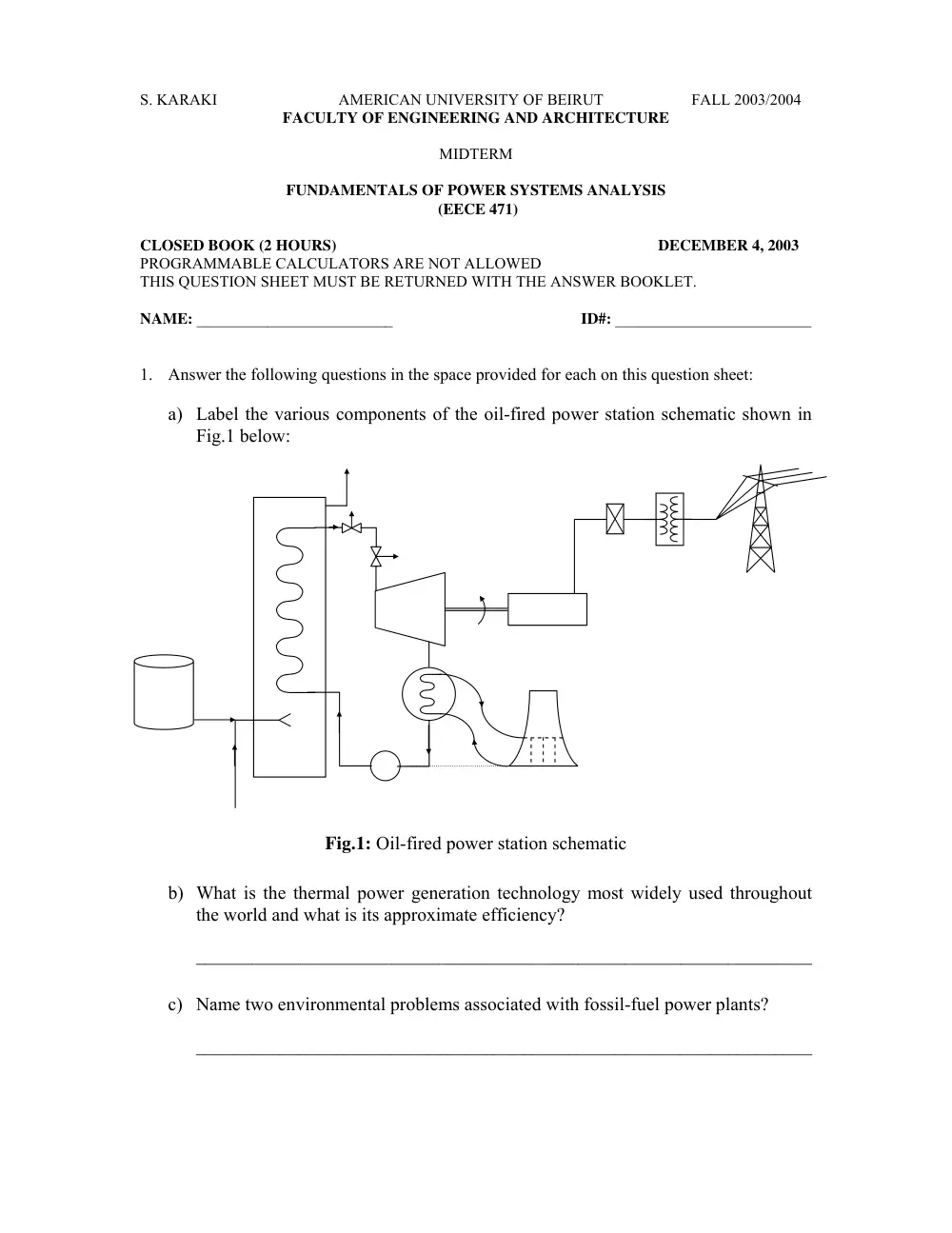
a) Label the various components of the oil-fired power station schematic shown in
Fig.1 below:
Fig.1: Oil-fired power station schematic
b) What is the thermal power generation technology most widely used throughout
the world and what is its approximate efficiency?
__________________________________________________________________
c) Name two environmental problems associated with fossil-fuel power plants?
__________________________________________________________________
EECE 471E
MIDTERM - FALL 2003/ 2004
Page 2/ 6
d) Why would the world with current technologies and resources face an energy
crisis in the next 50 to 150 years?
__________________________________________________________________
e) Name three types of renewable energy technologies?
__________________________________________________________________
f) Why do we raise the voltage to transmit a given amount of power over a long
distance?
__________________________________________________________________
g) When we design generators with higher rating which dimension is usually
increased, the diameter or the length of the generator and why?
__________________________________________________________________
h) What is the relationship between ac and dc resistances and why are they
different?
__________________________________________________________________
i) For a given line, how do the shunt capacitive susceptance and the series inductive
reactance in per unit change as we increase its operating voltage?
__________________________________________________________________
j) What is the surge impedance loading of a line?
__________________________________________________________________
2. A three-phase load draws 500 kW at a PF of 0.707 lagging from a 440 V line. It is
required to compensate the load and bring the PF of the compensation equipment and
load up to 0.9.
a) Determine the line current and reactive power supplied before compensation.
b) Determine the line current and reactive power supplied after compensation.
c) What is the kind of compensation equipment used and what is its size?
d) Draw a phasor diagram showing voltage and current before and after
compensation and comment on the effect of compensation on the system.
EECE 471E
MIDTERM - FALL 2003/ 2004
Page 3/ 6
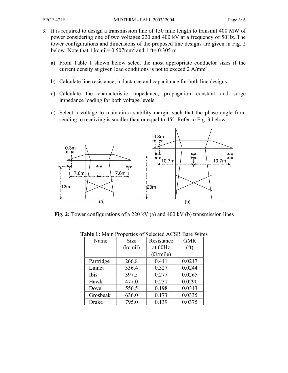
3. It is required to design a transmission line of 150 mile length to transmit 400 MW of
power considering one of two voltages 220 and 400 kV at a frequency of 50Hz. The
tower configurations and dimensions of the proposed line designs are given in Fig. 2
below. Note that 1 kcmil= 0.507mm2 and 1 ft= 0.305 m.
a) From Table 1 shown below select the most appropriate conductor sizes if the
current density at given load conditions is not to exceed 2 A/mm2.
b) Calculate line resistance, inductance and capacitance for both line designs.
c) Calculate the characteristic impedance, propagation constant and surge
impedance loading for both voltage levels.
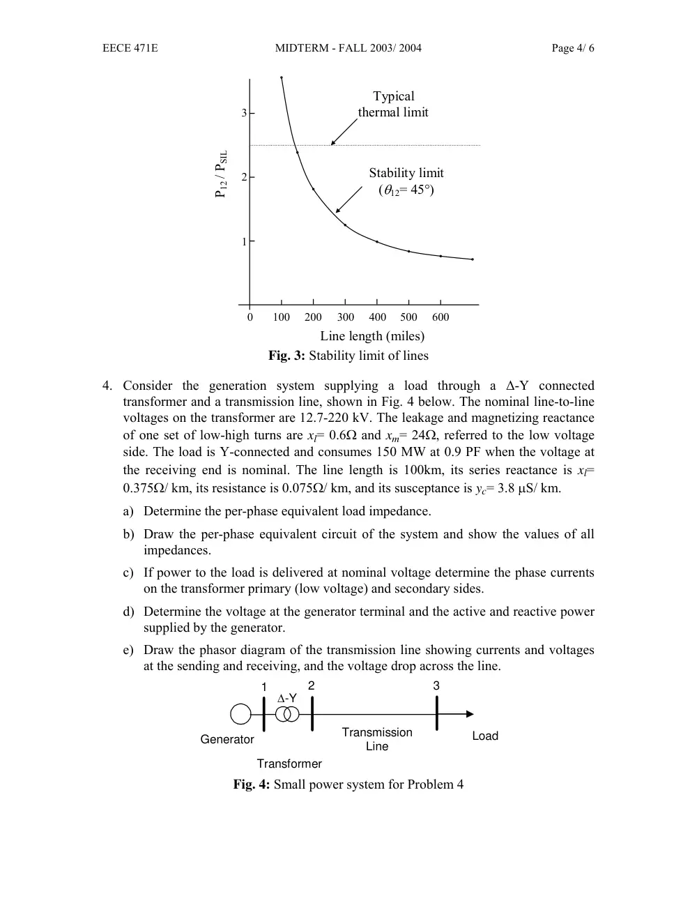
d) Select a voltage to maintain a stability margin such that the phase angle from
sending to receiving is smaller than or equal to 45°. Refer to Fig. 3 below.
12m
(a)
0.3m
7.6m
7.6m
20m
(b)
0.3m
10.7m
10.7m
Fig. 2: Tower configurations of a 220 kV (a) and 400 kV (b) transmission lines
Table 1: Main Properties of Selected ACSR Bare Wires
Name
Size
(kcmil)
Resistance
at 60Hz
(Ω/mile)
GMR
(ft)
Partridge
266.8
0.411
0.0217
Linnet
336.4
0.327
0.0244
Ibis
397.5
0.277
0.0265
Hawk
477.0
0.231
0.0290
Dove
556.5
0.198
0.0313
Grosbeak
636.0
0.173
0.0335
Drake
795.0
0.139
0.0375
EECE 471E
MIDTERM - FALL 2003/ 2004
Page 4/ 6
100
200
300
400
500
600
0
1
2
3
P12 / PSIL
Line length (miles)
Typical
thermal limit
Stability limit
(θ12= 45°)
Fig. 3: Stability limit of lines
4. Consider the generation system supplying a load through a ∆-Y connected
transformer and a transmission line, shown in Fig. 4 below. The nominal line-to-line
voltages on the transformer are 12.7-220 kV. The leakage and magnetizing reactance
of one set of low-high turns are xl= 0.6Ω and xm= 24Ω, referred to the low voltage
side. The load is Y-connected and consumes 150 MW at 0.9 PF when the voltage at
the receiving end is nominal. The line length is 100km, its series reactance is xl=
0.375Ω/ km, its resistance is 0.075Ω/ km, and its susceptance is yc= 3.8 µS/ km.
a) Determine the per-phase equivalent load impedance.
b) Draw the per-phase equivalent circuit of the system and show the values of all
impedances.
c) If power to the load is delivered at nominal voltage determine the phase currents
on the transformer primary (low voltage) and secondary sides.
d) Determine the voltage at the generator terminal and the active and reactive power
supplied by the generator.
e) Draw the phasor diagram of the transmission line showing currents and voltages
at the sending and receiving, and the voltage drop across the line.
Generator
Load
∆-Y
Transmission
Line
1
2
3
Transformer
Fig. 4: Small power system for Problem 4
EECE 471E
MIDTERM - FALL 2003/ 2004
Page 5/ 6
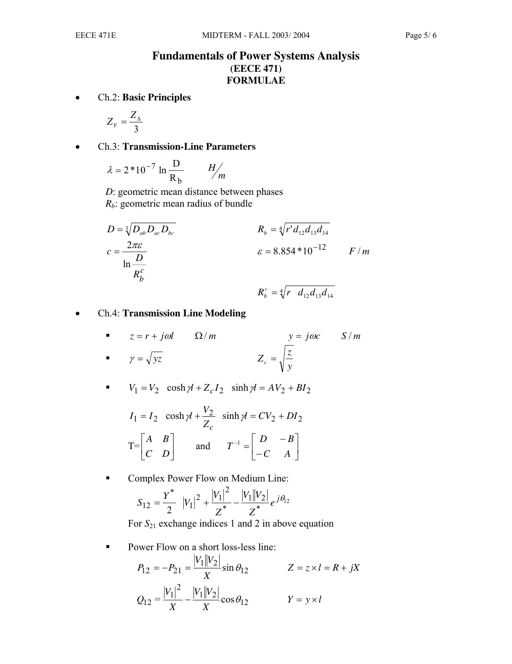
Fundamentals of Power Systems Analysis
(EECE 471)
FORMULAE
•
Ch.2: Basic Principles
3
ZY = Z∆
•
Ch.3: Transmission-Line Parameters
m
H
b
7
R
ln D
2*10
−
λ =
D: geometric mean distance between phases
Rb: geometric mean radius of bundle
3
bc
ac
ab
D D D
D =
4
14
' 12 13
r d d d
Rb =
c
b
R
D
c
ln
= 2πε
F / m
.8 854*10
−12
ε =
4
14
12 13
r d d d
R c
b =
•
Ch.4: Transmission Line Modeling
�
m
j l
r
z
Ω /
+
=
ω
S m
j c
y
/
= ω
�
yz
γ =
y
z
Z c =
�
2
2
2
2
1
sinh
cosh
BI
AV
l
Z I
l
V
V
c
+
=
+
=
γ
γ
2
2
2
2
1
sinh
cosh
DI
CV
l
Z
V
l
I
I
c
+
=
+
=
γ
γ
T=
⎥⎦
⎤
⎢⎣
⎡
D
C
B
A
and
⎥⎦
⎤
⎢⎣
⎡
−
−
− =
A
C
B
D
T
1
�
Complex Power Flow on Medium Line:
12
*
2
1
*
2
1
2
1
*
12
2
jθ
e
Z
V
V
Z
V
V
Y
S
−
+
=
For S21 exchange indices 1 and 2 in above equation
�
Power Flow on a short loss-less line:
12
2
1
21
12
sinθ
X
V V
P
P
=
= −
jX
R
l
z
Z
+
× =
=
12
2
1
2
1
12
cos
=
θ
X
V
V
X
V
Q
−
l
y
Y
×
=
EECE 471E
MIDTERM - FALL 2003/ 2004
Page 6/ 6
12
2
1
2
2
21
cos
=
Q
θ
X
V
V
X
V
−
l: length of line
�
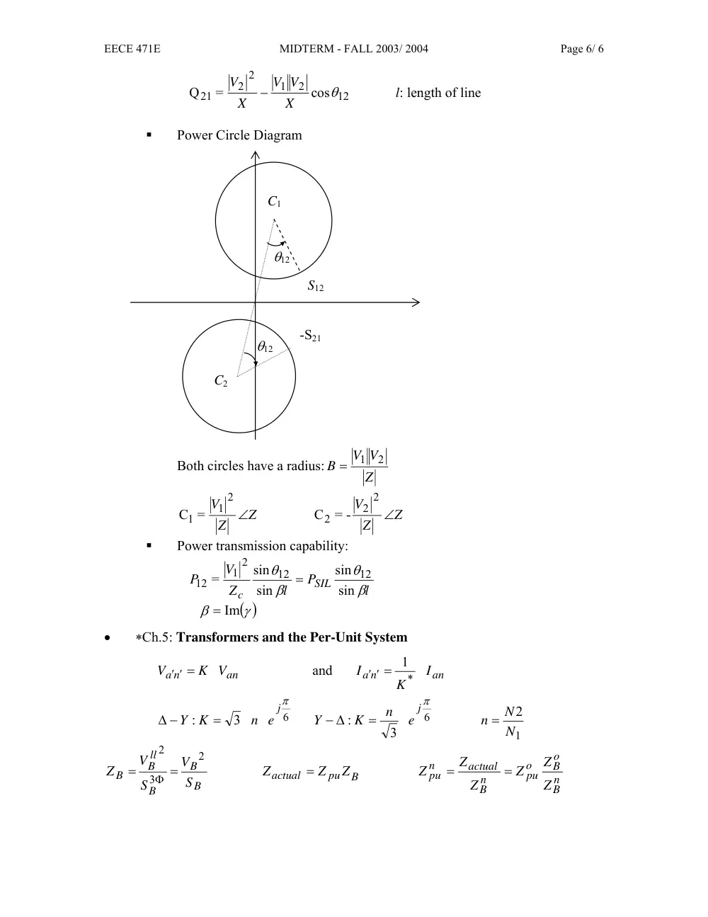
Power Circle Diagram
C1
C2
S12
-S21
θ12
θ12
Both circles have a radius:
Z
V V
B
2
1
=
Z
Z
V
∠
2
1
C1 =
Z
Z
V
∠
2
2
2
-
=
C
�
Power transmission capability:
l
P
l
Z
V
P
SIL
c
β
θ
β
θ
sin
sin
sin
sin
=
12
12
2
1
12
=
( )
γ
β
= Im
•
∗Ch.5: Transformers and the Per-Unit System
an
a n
K V
V
′ ′ =
and
an
a n
I
K
I
*
1
′ ′ =
6
3
:
jπ
n e
K
Y
=
∆ −
6
3
:
jπ
e
n
K
Y
=
− ∆
1
2
N
n = N
B
B
B
ll
B
B
S
V
S
V
Z
2
3
2
=
=
Φ
B
pu
actual
Z
Z
Z
=
n
B
o
B
o
pu
n
B
actual
n
pu
Z
Z
Z
Z
Z
Z
=
=