
EECE 471 Midterm, Fall 2007
American University of Beirut · Fundamentals of Power Systems Analysis · 4 pages


More EECE 471 files
Show the text of this exam
S. KARAKI
AMERICAN UNIVERSITY OF BEIRUT
FALL 2007/2008
FACULTY OF ENGINEERING AND ARCHITECTURE
MIDTERM EXAM
FUNDAMENTALS OF POWER SYSTEMS ANALYSIS
(EECE 471)
CLOSED BOOK (1.5 HOURS)
NOVEMBER 27, 2007
NAME: _________________________
ID#: _________________________
1. It is required to design a transmission line of 250 km length to supply a demand of
350 MW at 0.95 PF lagging considering one of three voltages 132, 275 and 400 kV at
a frequency of 50Hz with typical phase-to-phase spacing of 7, 10 m and 12 m,
respectively. Note that 1 kcmil= 0.507mm2 and 1 ft= 0.305 m. From previous
experience we know that the characteristic impedances of lines at 132, 275, and 400
kV are approximately equal to 325, 300, and 275 Ω, respectively. The land survey
indicated that we can build up to two towers side by side in the transmission corridor
each capable of carrying two circuits. The generator is rated at 13 kV 400MVA with
a rated power factor of 0.9 and the load has a rated voltage of 66kV.
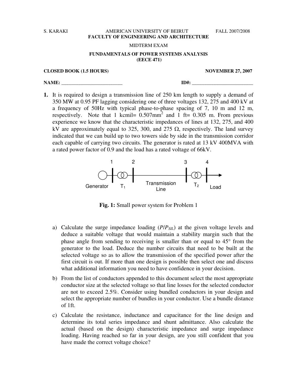
Generator
Load
Transmission
Line
1
2
3
T1
T2
4
Fig. 1: Small power system for Problem 1
a) Calculate the surge impedance loading (P/PSIL) at the given voltage levels and
deduce a suitable voltage that would maintain a stability margin such that the
phase angle from sending to receiving is smaller than or equal to 45° from the
generator to the load. Deduce the number circuits that need to be built at the
selected voltage so as to allow the transmission of the specified power after the
first circuit is out. If more than one design is possible then select one and discuss
what additional information you need to have confidence in your decision.
b) From the list of conductors appended to this document select the most appropriate
conductor size at the selected voltage so that line losses for the selected conductor
are not to exceed 2.5%. Consider using bundled conductors in your design and
select the appropriate number of bundles in your conductor. Use a bundle distance
of 1ft.
c) Calculate the resistance, inductance and capacitance for the line design and
determine its total series impedance and shunt admittance. Also calculate the
actual (based on the design) characteristic impedance and surge impedance
loading. Having reached so far in your design, are you still confident that you
have made the correct voltage choice?
EECE 471E
MIDTERM - FALL 2007/ 08
Page 2/ 5
d) Specify the transformers that you need to have in your design in terms of their
MVA rating, connection, and impedance.
e) Select a system base of 100MVA and the rated generator voltage as a base
voltage on the generator side. Model the load as an impedance and draw the per
unit equivalent circuit showing all impedance values. Show the calculation details
of some of your equivalent circuit parameters.
f) Calculate the ABCD constants of the overall transmission system and calculate
the voltage regulation of the transmission line including the transformers.
g) Calculate the sending end voltage and the active and reactive power supplied by
the generator. Comment on the results in as far as the voltage magnitude and
phase, and the active and reactive powers delivered by the generator.
2. Answer the following questions with the maximum number of 50 words without
using diagrams or equations. Just English sentences.
a) Discuss the issues that a planning engineer has to consider in selecting a
conductor size when designing a transmission line.
b) Explain the main reasons for dividing the conductor into bundles.
c) Explain a practical situation in transmission operation in which you need to
compensate using series capacitors. Where would you put the capacitors?
d) Explain a practical situation in transmission operation in which you need to
compensate using shunt capacitors. Where would you put the capacitor?
EECE 471E
MIDTERM - FALL 2007/ 08
Page 3/ 5
Fundamentals of Power Systems Analysis
(EECE 471)
FORMULAE
•
Ch.2: Basic Principles
3
ZY = Z∆
•
Ch.3: Transmission-Line Parameters
H m
R
D
l
b
ln
2*10
−7
=
D: geometric mean distance between phases
Rb: geometric mean radius of bundle
3
bc
ac
ab
D D D
D =
4
14
' 12 13
r d d d
Rb =
c
b
R
D
c
ln
= 2πε
F / m
.8 854*10
−12
ε =
4
14
12 13
r d d d
R c
b =
•
Ch.4: Transmission Line Modeling
�
m
j l
r
z
Ω /
+
=
ω
S m
j c
y
/
= ω
�
yz
γ =
y
z
Z c =
�
2
2
2
2
1
sinh
cosh
BI
AV
l
Z I
l
V
V
c
+
=
+
=
γ
γ
2
2
2
2
1
sinh
cosh
DI
CV
l
Z
V
l
I
I
c
+
=
+
=
γ
γ
�
⎟⎟
⎠
⎞
⎜⎜
⎝
⎛ +
=
=
= +
=
4
1
2
1
ZY
Y
C
Z
B
ZY
D
A
T=
⎥⎦
⎤
⎢⎣
⎡
D
C
B
A
and
⎥⎦
⎤
⎢⎣
⎡
−
−
− =
A
C
B
D
T
1
�
Complex Power Flow on Medium Line:
12
*
2
1
*
2
1
2
1
*
12
2
jθ
e
Z
V
V
Z
V
V
Y
S
−
+
=
For S21 exchange indices 1 and 2 in above equation
�
Power Flow on a short loss-less line:
12
2
1
21
12
sinθ
X
V V
P
P
=
= −
jX
R
l
z
Z
+
× =
=
EECE 471E
MIDTERM - FALL 2007/ 08
Page 4/ 5
12
2
1
2
1
12
cos
=
θ
X
V
V
X
V
Q
−
l
y
Y
×
=
12
2
1
2
2
21
cos
=
Q
θ
X
V
V
X
V
−
l: length of line
�
Power transmission capability:
l
P
V
V
l
Z
V
V
V
P
pu SIL
pu
c
R
pu
pu
β
θ
β
θ
sin
sin
sin
sin
=
12
2
1
12
2
2
1
12
=
( )
λ
π
γ
β
2
Im
≅
=
•
∗Ch.5: Transformers and the Per-Unit System
an
a n
K V
V
′ ′ =
and
an
a n
I
K
I
*
1
′ ′ =
6
3
:
j π
a e
K
Y
=
∆ −
6
3
1
:
j π
e
a
K
Y
=
− ∆
2
1
N
a = N
B
B
B
ll
B
B
S
V
S
V
Z
2
3
2
=
=
Φ
B
pu
actual
Z
Z
Z
=
n
B
o
B
o
pu
n
B
actual
n
pu
Z
Z
Z
Z
Z
Z
=
=