
EECE 473 Final, Spring 2005
American University of Beirut · Power Electronics · 2 pages · Prof. Sami Karaki
More EECE 473 files
Show the text of this final exam
EECE 473
FINAL EXAM - SPRING 2005
1/ 8
AMERICAN UNIVERSITY OF BEIRUT
S. KARAKI
FACULTY OF ENGINEERING AND ARCHITECTURE
JUNE 6, 2005
POWER ELECTRONICS (EECE 473)
FINAL EXAMINATION
CLASS OF EE 2006
CLOSED BOOK (3 HOURS)
PROGRAMMABLE CALCULATORS ARE NOT ALLOWED
THIS QUESTION SHEET MUST BE RETURNED WITH THE ANSWER BOOKLET.
NAME: _________________________
ID#: _________________________
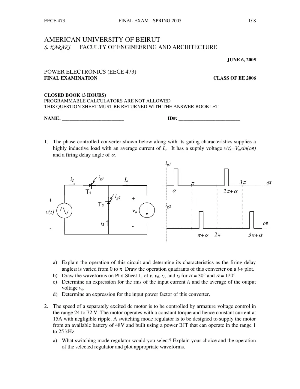
1. The phase controlled converter shown below along with its gating characteristics supplies a
highly inductive load with an average current of Io. It has a supply voltage v(t)=Vmsin(ωt)
and a firing delay angle of α.
ig2
2π
3π+α
ωt
π+α
ig1
π
2π+α
ωt
α
3π
+
-
vo
Io
T2
T1
+
-
v(t)
ig1
ig2
i1
i2
a) Explain the operation of this circuit and determine its characteristics as the firing delay
angleα is varied from 0 to π. Draw the operation quadrants of this converter on a i-v plot.
b) Draw the waveforms on Plot Sheet 1, of v, v0, i1, and i2 for α = 30° and α = 120°.
c) Determine an expression for the rms of the input current i1 and the average of the output
voltage v0.
d) Determine an expression for the input power factor of this converter.
2. The speed of a separately excited dc motor is to be controlled by armature voltage control in
the range 24 to 72 V. The motor operates with a constant torque and hence constant current at
15A with negligible ripple. A switching mode regulator is to be designed to supply the motor
from an available battery of 48V and built using a power BJT that can operate in the range 1
to 25 kHz.
a) What switching mode regulator would you select? Explain your choice and the operation
of the selected regulator and plot appropriate waveforms.
EECE 473
FINAL EXAM - SPRING 2005
2/ 8
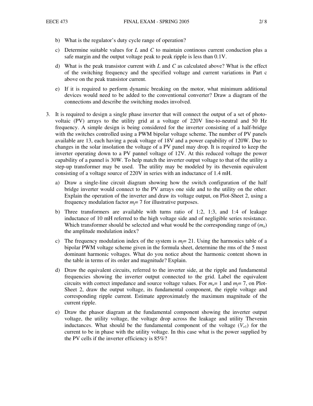
b) What is the regulator’s duty cycle range of operation?
c) Determine suitable values for L and C to maintain continous current conduction plus a
safe margin and the output voltage peak to peak ripple is less than 0.1V.
d) What is the peak transistor current with L and C as calculated above? What is the effect
of the switching frequency and the specified voltage and current variations in Part c
above on the peak transistor current.
e) If it is required to perform dynamic breaking on the motor, what minimum additional
devices would need to be added to the conventional converter? Draw a diagram of the
connections and describe the switching modes involved.
3. It is required to design a single phase inverter that will connect the output of a set of photo-
voltaic (PV) arrays to the utility grid at a voltage of 220V line-to-neutral and 50 Hz
frequency. A simple design is being considered for the inverter consisting of a half-bridge
with the switches controlled using a PWM bipolar voltage scheme. The number of PV panels
available are 13, each having a peak voltage of 18V and a power capability of 120W. Due to
changes in the solar insolation the voltage of a PV panel may drop. It is required to keep the
inverter operating down to a PV pannel voltage of 12V. At this reduced voltage the power
capability of a pannel is 30W. To help match the inverter output voltage to that of the utility a
step-up transformer may be used. The utility may be modeled by its thevenin equivalent
consisting of a voltage source of 220V in series with an inductance of 1.4 mH.
a) Draw a single-line circuit diagram showing how the switch configuration of the half
bridge inverter would connect to the PV arrays one side and to the utility on the other.
Explain the operation of the inverter and draw its voltage output, on Plot-Sheet 2, using a
frequency modulation factor mf= 7 for illustrative purposes.
b) Three transformers are available with turns ratio of 1:2, 1:3, and 1:4 of leakage
inductance of 10 mH referred to the high voltage side and of negligible series resistance.
Which transformer should be selected and what would be the corresponding range of (ma)
the amplitude modulation index?
c) The frequency modulation index of the system is mf= 21. Using the harmonics table of a
bipolar PWM voltage scheme given in the formula sheet, determine the rms of the 5 most
dominant harmonic voltages. What do you notice about the harmonic content shown in
the table in terms of its order and magnitude? Explain.
d) Draw the equivalent circuits, referred to the inverter side, at the ripple and fundamental
frequencies showing the inverter output connected to the grid. Label the equivalent
circuits with correct impedance and source voltage values. For ma= 1 and mf= 7, on Plot-
Sheet 2, draw the output voltage, its fundamental component, the ripple voltage and
corresponding ripple current. Estimate approximately the maximum magnitude of the
current ripple.
e) Draw the phasor diagram at the fundamental component showing the inverter output
voltage, the utility voltage, the voltage drop across the leakage and utility Thevenin
inductances. What should be the fundamental component of the voltage (Vo1) for the
current to be in phase with the utility voltage. In this case what is the power supplied by
the PV cells if the inverter efficiency is 85%?