
MECH 310 Exam 1, Fall 2009
American University of Beirut · Thermodynamics I · 13 pages


Showing the first 10 of 13 pages. Download the PDF to see all of it.
More MECH 310 files
- Exam 2 Solution Leen Alawieh · Fall 2017Exam · with solutionView
- Exam 1 Leen Alawieh With Solutions · Fall 2017Exam · with solutionView
- Exam 1 · Fall 2016ExamView
- Exam 1 · Summer 2012ExamView
- Exam 2 · Summer 2011ExamView
- Exam 1 · Spring 2011ExamView
- Exam 1 · Summer 2011ExamView
- Exam 1 with Solution · Fall 2011Exam · with solutionView
Show the text of this exam
MECH 310 Thermodynamics I
November 20, 2006
American University of Beirut, Fall 2006
Handout # Quiz 1
Quiz 1
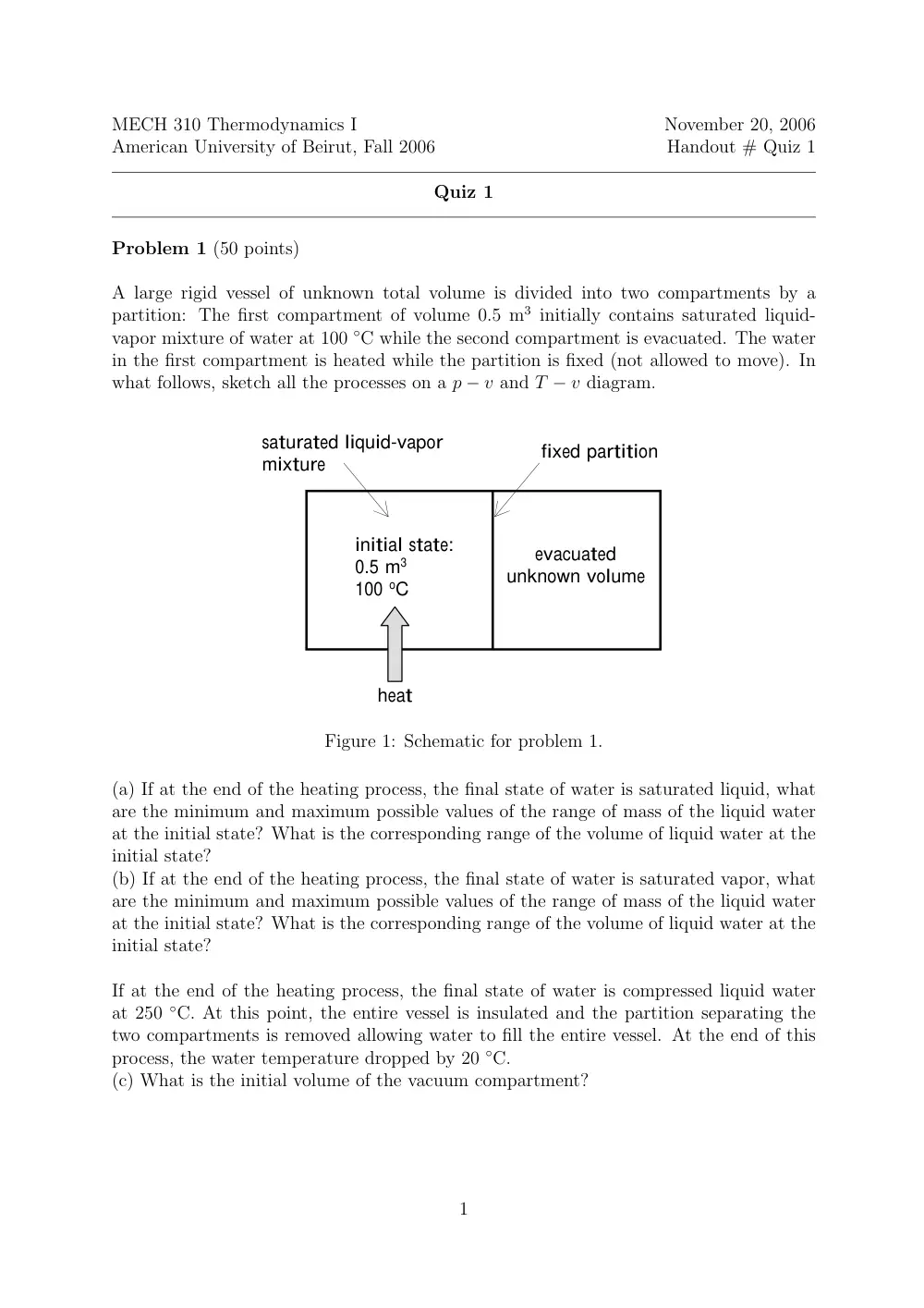
Problem 1 (50 points)
A large rigid vessel of unknown total volume is divided into two compartments by a
partition: The first compartment of volume 0.5 m3 initially contains saturated liquid-
vapor mixture of water at 100 ◦C while the second compartment is evacuated. The water
in the first compartment is heated while the partition is fixed (not allowed to move). In
what follows, sketch all the processes on a p − v and T − v diagram.
saturated liquid-vapor
mixture
initial state:
0.5 m3
100 oC
evacuated
unknown volume
heat
fixed partition
Figure 1: Schematic for problem 1.
(a) If at the end of the heating process, the final state of water is saturated liquid, what
are the minimum and maximum possible values of the range of mass of the liquid water
at the initial state? What is the corresponding range of the volume of liquid water at the
initial state?
(b) If at the end of the heating process, the final state of water is saturated vapor, what
are the minimum and maximum possible values of the range of mass of the liquid water
at the initial state? What is the corresponding range of the volume of liquid water at the
initial state?
If at the end of the heating process, the final state of water is compressed liquid water
at 250 ◦C. At this point, the entire vessel is insulated and the partition separating the
two compartments is removed allowing water to fill the entire vessel. At the end of this
process, the water temperature dropped by 20 ◦C.
(c) What is the initial volume of the vacuum compartment?
1
Problem 2 (50 points)
Consider the piston-cylinder arrangement shown in the Figure. The cylinder contains 3.5
grams of air and the piston is tightly sealed so that air cannot escape to the environment.
The piston mass is 1 kg and its diameter is 20 cm. Initially air inside the cylinder is
in thermodynamic equilibrium and the piston is at an elevation of 10 cm relative to the
bottom of the cylinder. Stops in the cylinder at an elevation of 15 cm relative to the
cylinder bottom prevent the cylinder from upward motion beyond that elevation. 1 kJ of
heat is slowly added via an electric resistance properly situated inside the bottom wall of
the cylinder.
(a) What are the initial pressure and temperature?
(b) Determine the final pressure and temperature.
(c) Determine the work done by the gas during the process and the work done against
atmosphere.
(d) Sketch the process on T − v and p − v diagrams.
Assume the following: The piston is frictionless, air may be modeled as an ideal gas, and
except for heat addition via the electric resistance no other forms of heat transfer take
place across the boundary. Neglect changes in potential energy and kinetic energy of the
air inside the cylinder. The ideal gas constant for air is R = 0.287 kJ/kg ◦K. State any
additional assumptions you make.
10 cm
15 cm
20 cm
Q = 1 kJ
g
atmosphere
1 bar
Figure 2: Schematic for problem 2.
2
MECH 310 Thermodynamics I
November 20, 2008
American University of Beirut, Fall 2008
Handout # Quiz 1
Quiz 1
Problem 1 (50 points)
A large rigid vessel of unknown total volume is divided into two compartments by a
partition: The first compartment of volume 0.5 m3 initially contains saturated liquid-
vapor mixture of water at 100 ◦C while the second compartment is evacuated. The water
in the first compartment is heated while the partition is fixed (not allowed to move). In
what follows, sketch all the processes on a p − v and T − v diagram.
saturated liquid-vapor
mixture
initial state:
0.5 m3
100 oC
evacuated
unknown volume
heat
fixed partition
Figure 1: Schematic for problem 1.
(a) If at the end of the heating process, the final state of water is saturated liquid, what
are the minimum and maximum possible values of the range of mass of the liquid water
at the initial state? What is the corresponding range of the volume of liquid water at the
initial state?
(b) If at the end of the heating process, the final state of water is saturated vapor, what
are the minimum and maximum possible values of the range of mass of the liquid water
at the initial state? What is the corresponding range of the volume of liquid water at the
initial state?
If at the end of the heating process, the final state of water is compressed liquid water
at 250 ◦C. At this point, the entire vessel is insulated and the partition separating the
two compartments is removed allowing water to fill the entire vessel. At the end of this
process, the water temperature dropped by 20 ◦C.
(c) What is the initial volume of the vacuum compartment?
1
Problem 1 Solution
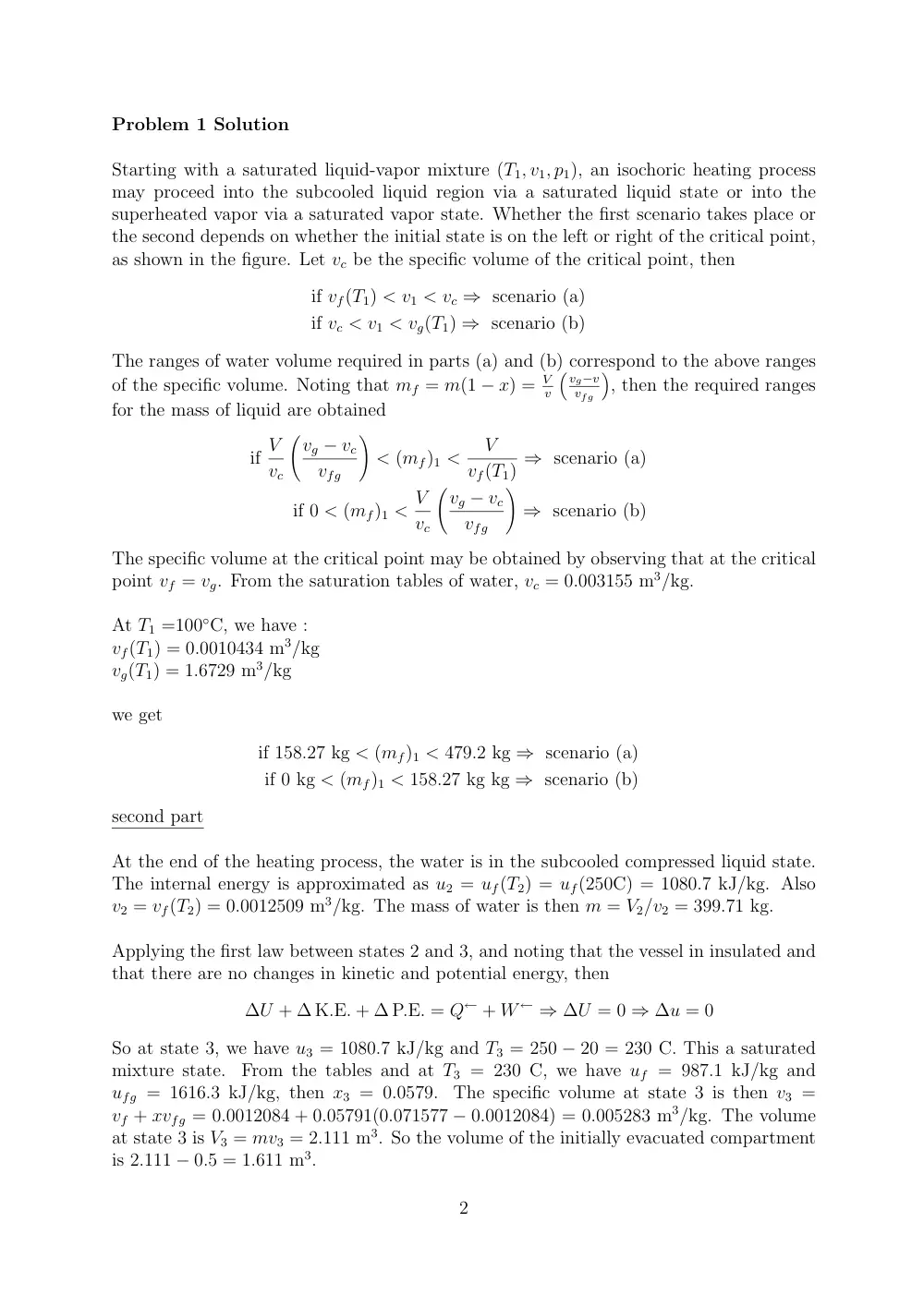
Starting with a saturated liquid-vapor mixture (T1, v1, p1), an isochoric heating process
may proceed into the subcooled liquid region via a saturated liquid state or into the
superheated vapor via a saturated vapor state. Whether the first scenario takes place or
the second depends on whether the initial state is on the left or right of the critical point,
as shown in the figure. Let vc be the specific volume of the critical point, then
if vf(T1) < v1 < vc ⇒ scenario (a)
if vc < v1 < vg(T1) ⇒ scenario (b)
The ranges of water volume required in parts (a) and (b) correspond to the above ranges
of the specific volume. Noting that mf = m(1 − x) = V
v
� vg−v
vfg
�
, then the required ranges
for the mass of liquid are obtained
if V
vc
�vg − vc
vfg
�
< (mf)1 <
V
vf(T1) ⇒ scenario (a)
if 0 < (mf)1 < V
vc
�vg − vc
vfg
�
⇒ scenario (b)
The specific volume at the critical point may be obtained by observing that at the critical
point vf = vg. From the saturation tables of water, vc = 0.003155 m3/kg.
At T1 =100◦C, we have :
vf(T1) = 0.0010434 m3/kg
vg(T1) = 1.6729 m3/kg
we get
if 158.27 kg < (mf)1 < 479.2 kg ⇒ scenario (a)
if 0 kg < (mf)1 < 158.27 kg kg ⇒ scenario (b)
second part
At the end of the heating process, the water is in the subcooled compressed liquid state.
The internal energy is approximated as u2 = uf(T2) = uf(250C) = 1080.7 kJ/kg. Also
v2 = vf(T2) = 0.0012509 m3/kg. The mass of water is then m = V2/v2 = 399.71 kg.
Applying the first law between states 2 and 3, and noting that the vessel in insulated and
that there are no changes in kinetic and potential energy, then
∆U + ∆ K.E. + ∆ P.E. = Q← + W ← ⇒ ∆U = 0 ⇒ ∆u = 0
So at state 3, we have u3 = 1080.7 kJ/kg and T3 = 250 − 20 = 230 C. This a saturated
mixture state.
From the tables and at T3 = 230 C, we have uf = 987.1 kJ/kg and
ufg = 1616.3 kJ/kg, then x3 = 0.0579.
The specific volume at state 3 is then v3 =
vf + xvfg = 0.0012084 + 0.05791(0.071577 − 0.0012084) = 0.005283 m3/kg. The volume
at state 3 is V3 = mv3 = 2.111 m3. So the volume of the initially evacuated compartment
is 2.111 − 0.5 = 1.611 m3.
2
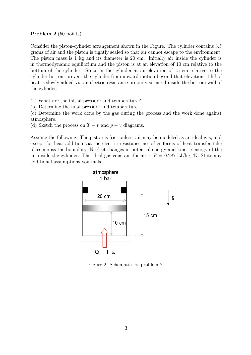
Problem 2 (50 points)
Consider the piston-cylinder arrangement shown in the Figure. The cylinder contains 3.5
grams of air and the piston is tightly sealed so that air cannot escape to the environment.
The piston mass is 1 kg and its diameter is 20 cm. Initially air inside the cylinder is
in thermodynamic equilibrium and the piston is at an elevation of 10 cm relative to the
bottom of the cylinder. Stops in the cylinder at an elevation of 15 cm relative to the
cylinder bottom prevent the cylinder from upward motion beyond that elevation. 1 kJ of
heat is slowly added via an electric resistance properly situated inside the bottom wall of
the cylinder.
(a) What are the initial pressure and temperature?
(b) Determine the final pressure and temperature.
(c) Determine the work done by the gas during the process and the work done against
atmosphere.
(d) Sketch the process on T − v and p − v diagrams.
Assume the following: The piston is frictionless, air may be modeled as an ideal gas, and
except for heat addition via the electric resistance no other forms of heat transfer take
place across the boundary. Neglect changes in potential energy and kinetic energy of the
air inside the cylinder. The ideal gas constant for air is R = 0.287 kJ/kg ◦K. State any
additional assumptions you make.
10 cm
15 cm
20 cm
Q = 1 kJ
g
atmosphere
1 bar
Figure 2: Schematic for problem 2.
3
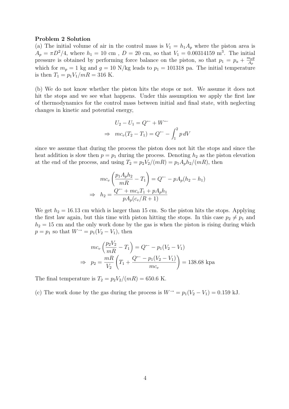
Problem 2 Solution
(a) The initial volume of air in the control mass is V1 = h1Ap where the piston area is
Ap = πD2/4, where h1 = 10 cm , D = 20 cm, so that V1 = 0.00314159 m3. The initial
pressure is obtained by performing force balance on the piston, so that p1 = pa + mpg
Ap
which for mp = 1 kg and g = 10 N/kg leads to p1 = 101318 pa. The initial temperature
is then T1 = p1V1/mR = 316 K.
(b) We do not know whether the piston hits the stops or not. We assume it does not
hit the stops and we see what happens. Under this assumption we apply the first law
of thermodynamics for the control mass between initial and final state, with neglecting
changes in kinetic and potential energy,
U2 − U1 = Q← + W ←
⇒
mcv(T2 − T1) = Q← −
� 2
1 p dV
since we assume that during the process the piston does not hit the stops and since the
heat addition is slow then p = p1 during the process. Denoting h2 as the piston elevation
at the end of the process, and using T2 = p2V2/(mR) = p1Aph2/(mR), then
mcv
�p1Aph2
mR
− T1
�
= Q← − pAp(h2 − h1)
⇒
h2 = Q← + mcvT1 + pAph1
pAp(cv/R + 1)
We get h2 = 16.13 cm which is larger than 15 cm. So the piston hits the stops. Applying
the first law again, but this time with piston hitting the stops. In this case p2 ̸= p1 and
h2 = 15 cm and the only work done by the gas is when the piston is rising during which
p = p1 so that W → = p1(V2 − V1), then
mcv
�p2V2
mR − T1
�
= Q← − p1(V2 − V1)
⇒
p2 = mR
V2
�
T1 + Q← − p1(V2 − V1)
mcv
�
= 138.68 kpa
The final temperature is T2 = p2V2/(mR) = 650.6 K.
(c) The work done by the gas during the process is W → = p1(V2 − V1) = 0.159 kJ.
4
MECH 310 Thermodynamics I
November 20, 2007
American University of Beirut, Fall 2007
Handout # Quiz 1
Quiz 1
• This is a closed book exam.
• You have 90 minutes.
• Write your name and section number on both the question and answer sheets.
• It is recommended that you read the whole exam before you start solving.
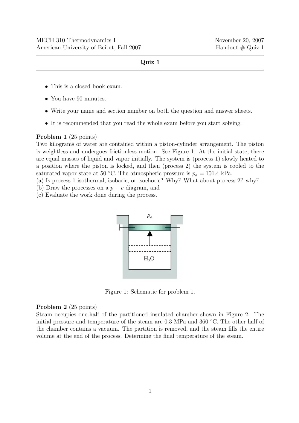
Problem 1 (25 points)
Two kilograms of water are contained within a piston-cylinder arrangement. The piston
is weightless and undergoes frictionless motion. See Figure 1. At the initial state, there
are equal masses of liquid and vapor initially. The system is (process 1) slowly heated to
a position where the piston is locked, and then (process 2) the system is cooled to the
saturated vapor state at 50 ◦C. The atmospheric pressure is pa = 101.4 kPa.
(a) Is process 1 isothermal, isobaric, or isochoric? Why? What about process 2? why?
(b) Draw the processes on a p − v diagram, and
(c) Evaluate the work done during the process.
H2O
H2O
vacuum
H2O
pa
pa
Figure 1: Schematic for problem 1.
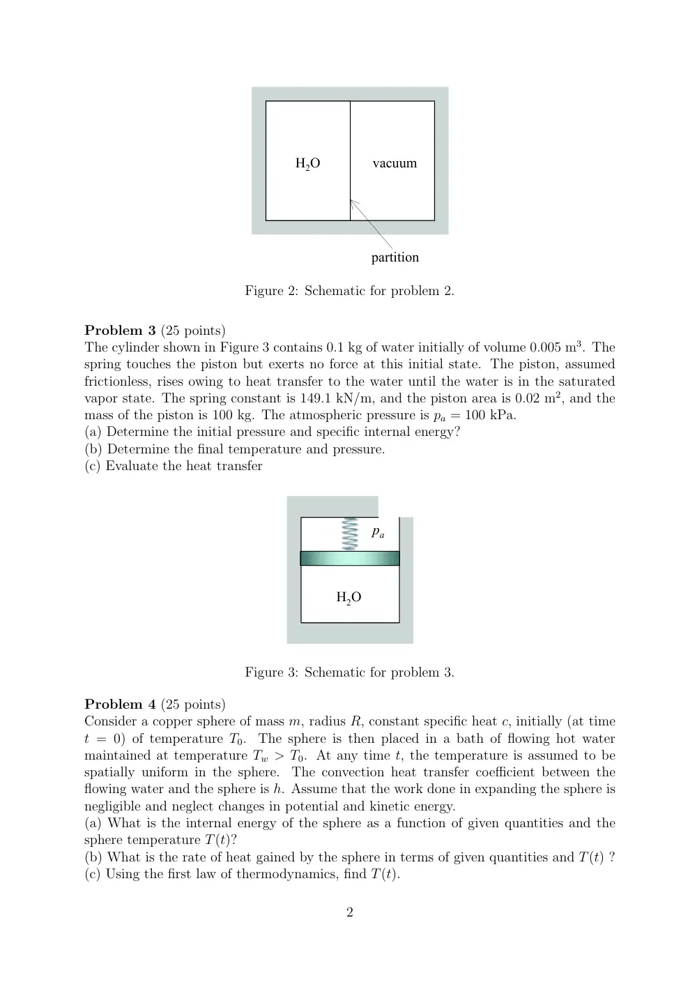
Problem 2 (25 points)
Steam occupies one-half of the partitioned insulated chamber shown in Figure 2. The
initial pressure and temperature of the steam are 0.3 MPa and 360 ◦C. The other half of
the chamber contains a vacuum. The partition is removed, and the steam fills the entire
volume at the end of the process. Determine the final temperature of the steam.
1
H2O
H2O
vacuum
partition
Figure 2: Schematic for problem 2.
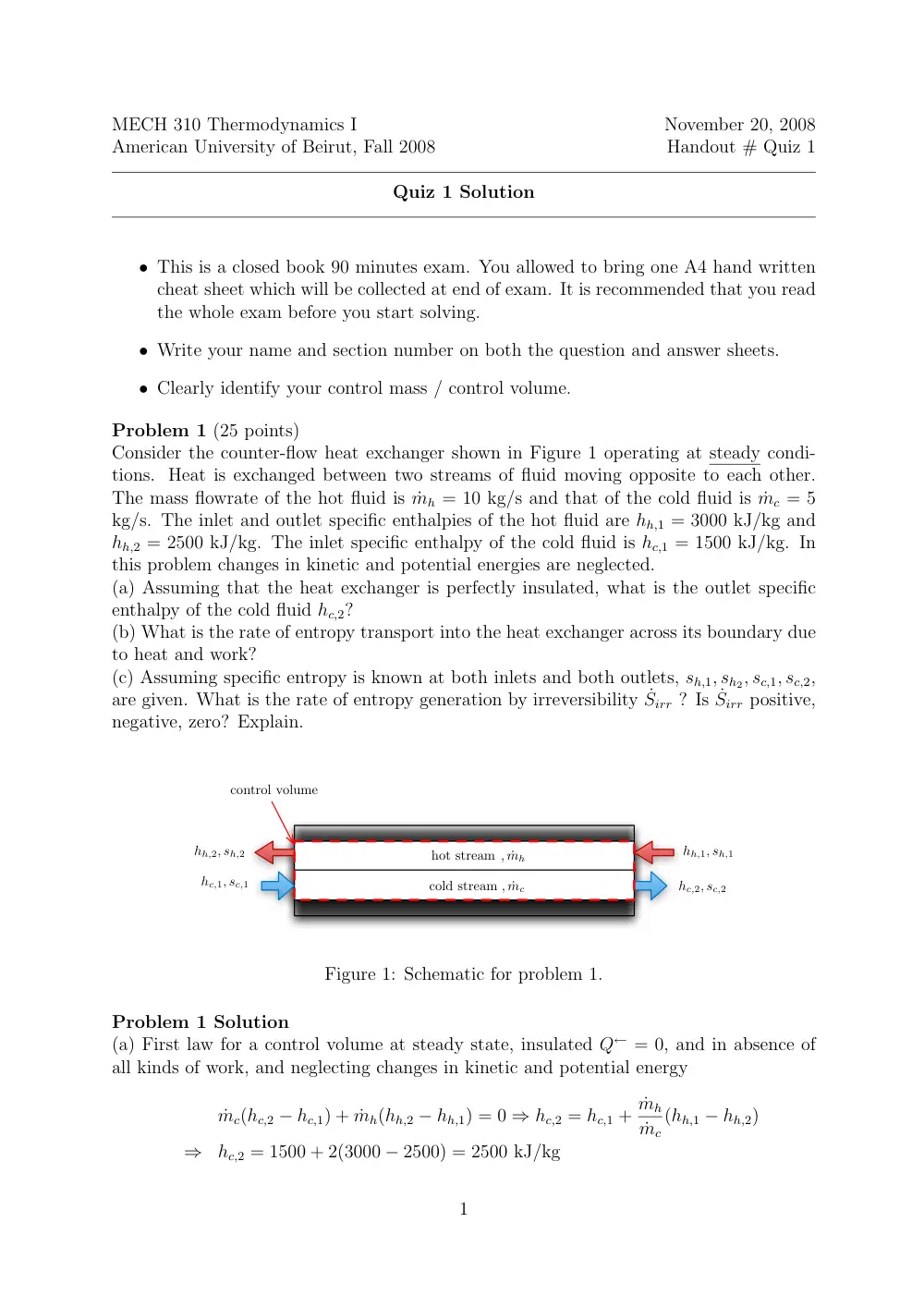
Problem 3 (25 points)
The cylinder shown in Figure 3 contains 0.1 kg of water initially of volume 0.005 m3. The
spring touches the piston but exerts no force at this initial state. The piston, assumed
frictionless, rises owing to heat transfer to the water until the water is in the saturated
vapor state. The spring constant is 149.1 kN/m, and the piston area is 0.02 m2, and the
mass of the piston is 100 kg. The atmospheric pressure is pa = 100 kPa.
(a) Determine the initial pressure and specific internal energy?
(b) Determine the final temperature and pressure.
(c) Evaluate the heat transfer
H2O
H2O
vacuum
partition
H2O
pa
pa
Figure 3: Schematic for problem 3.
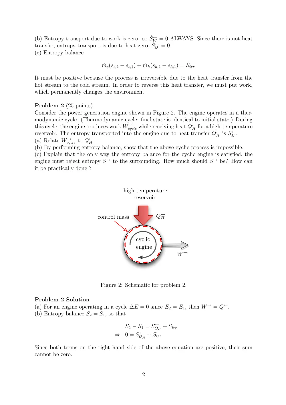
Problem 4 (25 points)
Consider a copper sphere of mass m, radius R, constant specific heat c, initially (at time
t = 0) of temperature T0.
The sphere is then placed in a bath of flowing hot water
maintained at temperature Tw > T0. At any time t, the temperature is assumed to be
spatially uniform in the sphere.
The convection heat transfer coefficient between the
flowing water and the sphere is h. Assume that the work done in expanding the sphere is
negligible and neglect changes in potential and kinetic energy.
(a) What is the internal energy of the sphere as a function of given quantities and the
sphere temperature T(t)?
(b) What is the rate of heat gained by the sphere in terms of given quantities and T(t) ?
(c) Using the first law of thermodynamics, find T(t).
2
MECH 310 Thermodynamics I
November 20, 2008
American University of Beirut, Fall 2008
Handout # Quiz 1
Quiz 1 Solution
• This is a closed book 90 minutes exam. You allowed to bring one A4 hand written
cheat sheet which will be collected at end of exam. It is recommended that you read
the whole exam before you start solving.
• Write your name and section number on both the question and answer sheets.
• Clearly identify your control mass / control volume.
Problem 1 (25 points)
Consider the counter-flow heat exchanger shown in Figure 1 operating at steady condi-
tions. Heat is exchanged between two streams of fluid moving opposite to each other.
The mass flowrate of the hot fluid is ˙mh = 10 kg/s and that of the cold fluid is ˙mc = 5
kg/s. The inlet and outlet specific enthalpies of the hot fluid are hh,1 = 3000 kJ/kg and
hh,2 = 2500 kJ/kg. The inlet specific enthalpy of the cold fluid is hc,1 = 1500 kJ/kg. In
this problem changes in kinetic and potential energies are neglected.
(a) Assuming that the heat exchanger is perfectly insulated, what is the outlet specific
enthalpy of the cold fluid hc,2?
(b) What is the rate of entropy transport into the heat exchanger across its boundary due
to heat and work?
(c) Assuming specific entropy is known at both inlets and both outlets, sh,1, sh2, sc,1, sc,2,
are given. What is the rate of entropy generation by irreversibility ˙Sirr ? Is ˙Sirr positive,
negative, zero? Explain.
cold stream
hot stream
hh,1, sh,1
hh,2, sh,2
hc,1, sc,1
hc,2, sc,2
, ˙mh
, ˙mc
control volume
Figure 1: Schematic for problem 1.
Problem 1 Solution
(a) First law for a control volume at steady state, insulated Q← = 0, and in absence of
all kinds of work, and neglecting changes in kinetic and potential energy
˙mc(hc,2 − hc,1) + ˙mh(hh,2 − hh,1) = 0 ⇒ hc,2 = hc,1 + ˙mh
˙mc
(hh,1 − hh,2)
⇒
hc,2 = 1500 + 2(3000 − 2500) = 2500 kJ/kg
1
(b) Entropy transport due to work is zero. so ˙S←
W = 0 ALWAYS. Since there is not heat
transfer, entropy transport is due to heat zero; ˙S←
Q = 0.
(c) Entropy balance
˙mc(sc,2 − sc,1) + ˙mh(sh,2 − sh,1) = ˙Sirr
It must be positive because the process is irreversible due to the heat transfer from the
hot stream to the cold stream. In order to reverse this heat transfer, we must put work,
which permanently changes the environment.
Problem 2 (25 points)
Consider the power generation engine shown in Figure 2. The engine operates in a ther-
modynamic cycle. (Thermodynamic cycle: final state is identical to initial state.) During
this cycle, the engine produces work W →
cycle while receiving heat Q←
H for a high-temperature
reservoir. The entropy transported into the engine due to heat transfer Q←
H is S←
H .
(a) Relate W →
cycle to Q←
H .
(b) By performing entropy balance, show that the above cyclic process is impossible.
(c) Explain that the only way the entropy balance for the cyclic engine is satisfied, the
engine must reject entropy S→ to the surrounding. How much should S→ be? How can
it be practically done ?
cyclic
engine
high temperature
reservoir
Q←
H
W →
control mass
Figure 2: Schematic for problem 2.
Problem 2 Solution
(a) For an engine operating in a cycle ∆E = 0 since E2 = E1, then W → = Q←.
(b) Entropy balance S2 = S1, so that
S2 − S1 = S←
QH + Sirr
⇒
0 = S←
QH + Sirr
Since both terms on the right hand side of the above equation are positive, their sum
cannot be zero.
2
(c) We need to remove entropy by rejecting heat Q→
L to the surrounding so that entropy
balance becomes
0 = S←
QH − S→
QL + Sirr
⇒
S→
QL = S←
QH + Sirr
It is impossible for a cyclic engine to produce work while interacting with only one thermal
reservoir.
Problem 3 (25 points)
We consider isothermal expansion of 10 kg of air in the the piston cylinder arrangement
of Figure 3. Air is modeled as an ideal gas with R = 0.287 kJ/kg.K. During the process
from initial (equilibrium) state 1 to final (equilibrium) state 2, heat is added to the
gas by conduction across a wall of thickness h = 0.5 cm, area A = 0.1 m2, and thermal
conductivity k = 50 W/(m.K). On the gas side of the conducting wall, the gas temperature
is T = 50 ◦C and on the outer side of the wall, the temperature is To = 100 ◦C .
(a) If heat is conducted steadily through the wall into the gas from time t1 = 0 to times
t2 = 10 sec, what is the heat gained by gas Q←? [Hint: conduction heat flux is q = −k∇T
and assume linear temperature distribution on conducting wall.]
(b) Can we neglect changes in kinetic energy and changes in potential energy, i.e. KE2-
KE1 and PE2-PE1? Why?
(c) What is the work done by the gas during the expansion process? If the initial volume
is V1 = 0.01 m3, what is the final volume V2, temperature T2, and pressure p2?
piston
conduction heat transfer
Q←
ideal gas
Temperature T
Temperature To
h
area A
control mass
Figure 3: Schematic for problem 3.
Problem 3 Solution
(a) The heat gain per unit area per unit time is q = k(To − Ti)/h = 50(100 − 50)/0.005 =
500 kJ/m2.s. The rate of heat gain is then qA = 500×0.1 = 50 kW. The heat transferred
over the period of 10 s is then Q← = qA(t2 − t1) = 500 kJ.
(b) The changes in potential and kinetic energy may be neglected if |∆K.E.| << Q←
3
and |∆P.E.| << Q←. Some of you stated that they should be less that ∆U, which is
zero in our problem, the process being isothermal. So this last statement is wrong. For
equilibrium or quasi-equilibrium initial and final states, the gas velocities are small, and
when multiplied by the gas density, which is small, yield small |∆K.E.|. Note that for
(exact) equilibrium states, K.E.1 = 0 and K.E.2 = 0. As for changes in potential energy
|∆P.E.| = ρg(V2 − V1) which for small ρ and |V2 − V1| may be neglected with respect to
Q←.
(c) First law of thermodynamics for a control mass between state 1 and state 2 is
E2 − E1 = Q← + W ←
Since the process is isothermal U2 − U1 = 0, neglecting changes in kinetic and potential
energy, we get W → = Q← = 500 kJ. The work done by a system during an isothermal
process is W → = mRT ln V2
V1 ⇒ V2 = V1e
W →
mRT = 0.01 × 1.715 = 0.0175 m3. Ideal has law
leads to p2 = 54055 pa.
Problem 4 (35 points)
In this problem, we investigate the thermodynamics of friction within a fluid. In par-
ticular, we consider a layer of lubricant (oil) of viscosity µ and density ρ. The oil layer
separates a fixed wall (which could be the cylinder wall) from a moving wall (which could
be the piston wall). The problem is steady and the upper wall velocity is V , and the oil
layer thickness is h. The velocity distribution inside the oil may be obtained from fluid
mechanics to be u(y) = V y
h.
(a) The friction (viscous) force per unit area acting on (the lower side of) the moving
wall is τw = −µ (∂u/∂y)y=h. In which direction does this force pull the upper wall with
respect to it motion? Explain the molecular origins of this force.
(b) What is the rate of work done on the oil assuming that the dimensions of the oil layer
in the x and z are respectively 1 m and 1 m.
(c) If the oil enters the left side (i.e. at x = 0) at temperature T, what is its temperature
at exit (i.e. at x = 1 m). Assume the oil layer to be thermally insulated at the upper and
lower wall sides. Assume also that the specific heat of oil, cv, does not change over the
ranges of temperatures involved in the problem.
(d) Given initial and final equilibrium states, is the work done by the friction force path-
dependent? Support your answer by one or more scenarios.
(e) Is this process reversible? Explain.
Problem 4 Solution
(a) Friction pulls the wall in a direction opposite to its motion. Friction is due to the
tangential component of momentum transfer between adjacent layers of molecules that
due to their temperature are randomly oscillating about a mean position.
(b) The rate work done on oil per unit area is given by
˙W
A = 1
A
∂
∂t
�
F · dx =
� F
A · dV
Notice that the force per unit area on the oil is opposite to the force per unit area on the
upper wall (action/reaction) so that F/A = −τwˆx. The fluid velocity at y = h is V = V ˆx
4
piston
moving wall
fixed wall
oil, viscosity µ
density ρ
wall velocity V
x
y
oil velocity
V y
h
h
control volume
Figure 4: Schematic for problem 4.
so that
˙W
A = −τwV = µV
�∂u
∂y
�
y=h
= µV 2
h
The rate of work done on the oil is then
˙W ← =
˙W
A A = µV 2A
h
where A = 1 m2.
(c) For the control volume chosen to contain the oil of thickness h and extending from
x = 0 to x = 1 m, applying the first law for a control volume and noting that the flow is
steady, and noting that changes in kinetic energy and potential energy between inlet and
outlet is zero, then
˙W ← = ˙m(h2 − h1)
where ˙m = ρV h/2. Considering oil to be compressed liquid for which h ≃ h(T), then
h2 − h1 = cp(T2 − T1) so that
T2 = T1 + 2
˙W ←
ρV hcp
= T1 + 2 µV
ρcph2
where it was assumed that cp does not change over the range [T1, T2].
(d) The work done by friction on the oil is path dependent. We could replace the work
effect by heat transfer into the oil that yields the same temperature rise. In the first
scenario ˙W ← = µV 2/h, Q← = 0 and in the second scenario ˙W ← = 0, Q← = µV 2/h. In
both cases we have the same inlet and outlet states.
(e) The process is irreversible because if we isolate the system, which amounts to stopping
the upper wall, there will internal heat transfer in the oil until a final uniform temperature
is reached at equilibrium.
5