
MECH 310 Final, Fall 2008
American University of Beirut · Thermodynamics I · 3 pages
More MECH 310 files
- Final · Spring 2011Final examView
- Final · Spring 2011Final examView
- Final · Summer 2011Final examView
- Final · Spring 2010Final examView
- Final · Fall 2009Final examView
- Essay Chapter 3 · Fall 2017ChapterView
- Exam 2 Solution Leen Alawieh · Fall 2017Exam · with solutionView
- Exam 1 Leen Alawieh With Solutions · Fall 2017Exam · with solutionView
Show the text of this final exam
MECH 310 Thermodynamics I
January 31, 2008
American University of Beirut, Fall 2008
Handout # Final Exam
Final Exam
• This is a 120 minutes exam.
• You are allowed to bring in 1 cheat sheet (2 A4 pages).
• You are advised to read the whole exam before you start.
• Make sure you state all the assumptions you make and that you clearly identify any
control mass or control volume you utilize in your analysis.
• Good luck!
Name & Section:
Problem 1 [35 points]
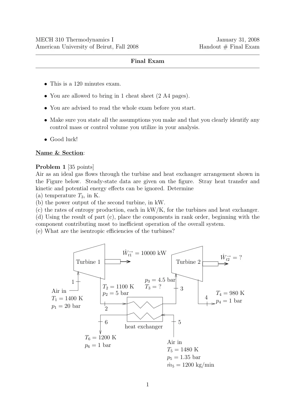
Air as an ideal gas flows through the turbine and heat exchanger arrangement shown in
the Figure below. Steady-state data are given on the figure. Stray heat transfer and
kinetic and potential energy effects can be ignored. Determine
(a) temperature T3, in K.
(b) the power output of the second turbine, in kW.
(c) the rates of entropy production, each in kW/K, for the turbines and heat exchanger.
(d) Using the result of part (c), place the components in rank order, beginning with the
component contributing most to inefficient operation of the overall system.
(e) What are the isentropic efficiencies of the turbines?
˙W →
t2 = ?
Turbine 2
Turbine 1
Air in
T1 = 1400 K
p1 = 20 bar
1
3
4
6
heat exchanger
T6 = 1200 K
p6 = 1 bar
Air in
T5 = 1480 K
p5 = 1.35 bar
˙m5 = 1200 kg/min
˙W →
t1 = 10000 kW
T4 = 980 K
p4 = 1 bar
5
T2 = 1100 K
p2 = 5 bar
p3 = 4.5 bar
T3 = ?
2
1
Problem 2 [35 points]
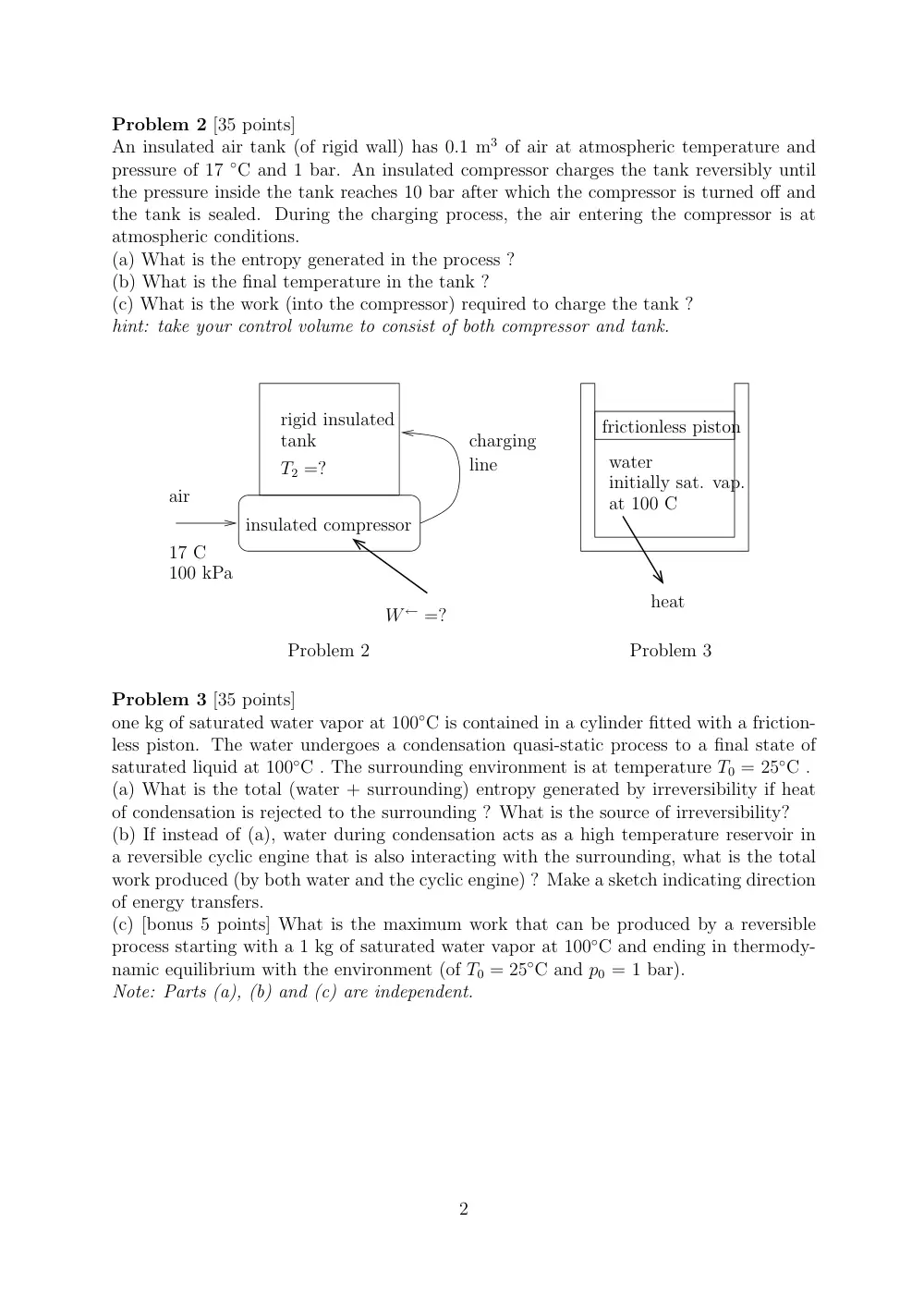
An insulated air tank (of rigid wall) has 0.1 m3 of air at atmospheric temperature and
pressure of 17 ◦C and 1 bar. An insulated compressor charges the tank reversibly until
the pressure inside the tank reaches 10 bar after which the compressor is turned off and
the tank is sealed. During the charging process, the air entering the compressor is at
atmospheric conditions.
(a) What is the entropy generated in the process ?
(b) What is the final temperature in the tank ?
(c) What is the work (into the compressor) required to charge the tank ?
hint: take your control volume to consist of both compressor and tank.
Problem 3
rigid insulated
tank
insulated compressor
air
100 kPa
17 C
W ← =?
T2 =?
charging
line
frictionless piston
water
initially sat. vap.
at 100 C
heat
Problem 2
1
Problem 3 [35 points]
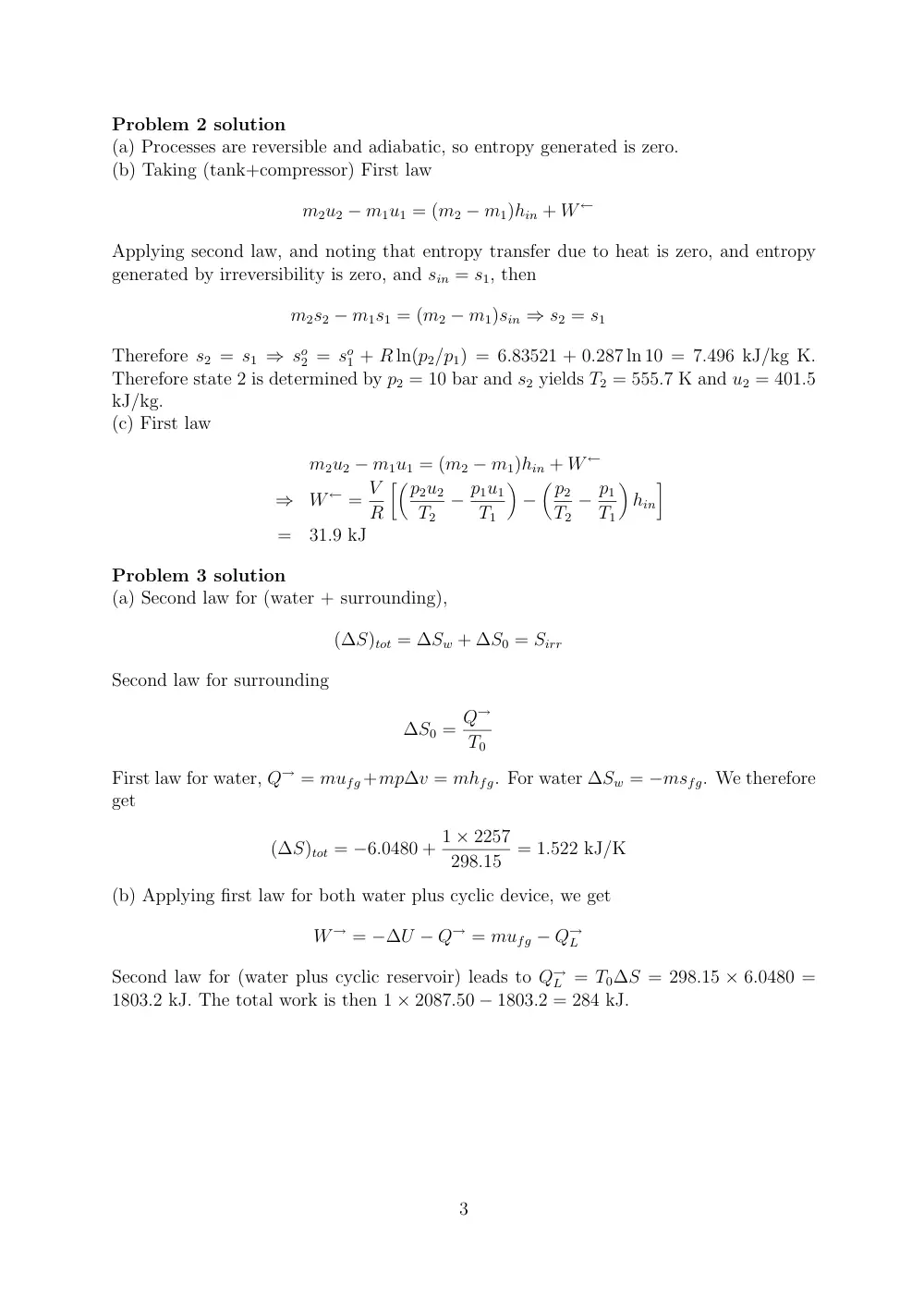
one kg of saturated water vapor at 100◦C is contained in a cylinder fitted with a friction-
less piston. The water undergoes a condensation quasi-static process to a final state of
saturated liquid at 100◦C . The surrounding environment is at temperature T0 = 25◦C .
(a) What is the total (water + surrounding) entropy generated by irreversibility if heat
of condensation is rejected to the surrounding ? What is the source of irreversibility?
(b) If instead of (a), water during condensation acts as a high temperature reservoir in
a reversible cyclic engine that is also interacting with the surrounding, what is the total
work produced (by both water and the cyclic engine) ? Make a sketch indicating direction
of energy transfers.
(c) [bonus 5 points] What is the maximum work that can be produced by a reversible
process starting with a 1 kg of saturated water vapor at 100◦C and ending in thermody-
namic equilibrium with the environment (of T0 = 25◦C and p0 = 1 bar).
Note: Parts (a), (b) and (c) are independent.
2
Problem 2 solution
(a) Processes are reversible and adiabatic, so entropy generated is zero.
(b) Taking (tank+compressor) First law
m2u2 − m1u1 = (m2 − m1)hin + W ←
Applying second law, and noting that entropy transfer due to heat is zero, and entropy
generated by irreversibility is zero, and sin = s1, then
m2s2 − m1s1 = (m2 − m1)sin ⇒ s2 = s1
Therefore s2 = s1 ⇒ so
2 = so
1 + R ln(p2/p1) = 6.83521 + 0.287 ln 10 = 7.496 kJ/kg K.
Therefore state 2 is determined by p2 = 10 bar and s2 yields T2 = 555.7 K and u2 = 401.5
kJ/kg.
(c) First law
m2u2 − m1u1 = (m2 − m1)hin + W ←
⇒
W ← = V
R
��p2u2
T2
− p1u1
T1
�
−
�p2
T2
− p1
T1
�
hin
�
=
31.9 kJ
Problem 3 solution
(a) Second law for (water + surrounding),
(∆S)tot = ∆Sw + ∆S0 = Sirr
Second law for surrounding
∆S0 = Q→
T0
First law for water, Q→ = mufg +mp∆v = mhfg. For water ∆Sw = −msfg. We therefore
get
(∆S)tot = −6.0480 + 1 × 2257
298.15
= 1.522 kJ/K
(b) Applying first law for both water plus cyclic device, we get
W → = −∆U − Q→ = mufg − Q→
L
Second law for (water plus cyclic reservoir) leads to Q→
L = T0∆S = 298.15 × 6.0480 =
1803.2 kJ. The total work is then 1 × 2087.50 − 1803.2 = 284 kJ.
3