
MECH 310 Final, Spring 2011
American University of Beirut · Thermodynamics I · 12 pages
Showing the first 10 of 12 pages. Download the PDF to see all of it.
More MECH 310 files
- Final · Spring 2011Final examView
- Final · Summer 2011Final examView
- Final · Spring 2010Final examView
- Final · Fall 2009Final examView
- Final · Fall 2008Final examView
- Essay Chapter 3 · Fall 2017ChapterView
- Exam 2 Solution Leen Alawieh · Fall 2017Exam · with solutionView
- Exam 1 Leen Alawieh With Solutions · Fall 2017Exam · with solutionView
Show the text of this final exam
MECH 310 THERMODYNAMICS I
FINAL (OPEN BOOK 180 MINUTES) SOLUTIONS
2nd June 2010
MULTIPLE CHOICE QUESTIONS
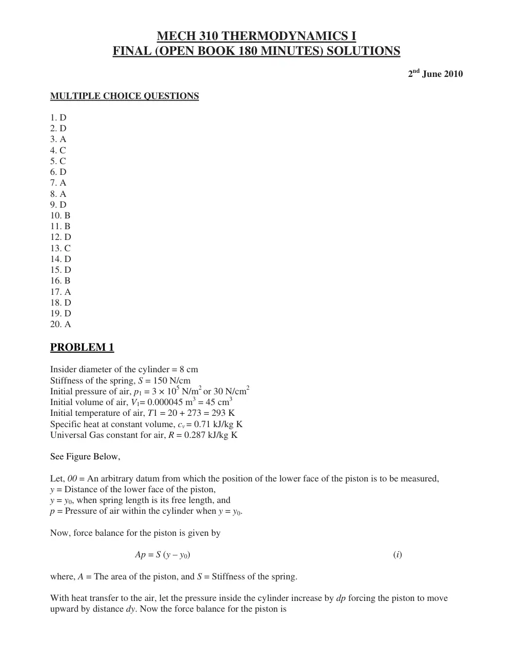
1. D
2. D
3. A
4. C
5. C
6. D
7. A
8. A
9. D
10. B
11. B
12. D
13. C
14. D
15. D
16. B
17. A
18. D
19. D
20. A
PROBLEM 1
Insider diameter of the cylinder = 8 cm
Stiffness of the spring, S = 150 N/cm
Initial pressure of air, p1 = 3 × 10⁵ N/m2 or 30 N/cm2
Initial volume of air, V1= 0.000045 m3 = 45 cm3
Initial temperature of air, T1 = 20 + 273 = 293 K
Specific heat at constant volume, cv = 0.71 kJ/kg K
Universal Gas constant for air, R = 0.287 kJ/kg K
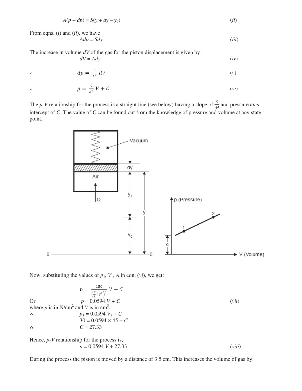
See Figure Below,
Let, 00 = An arbitrary datum from which the position of the lower face of the piston is to be measured,
y = Distance of the lower face of the piston,
y = y0, when spring length is its free length, and
p = Pressure of air within the cylinder when y = y0.
Now, force balance for the piston is given by
Ap = S (y – y0)
(i)
where, A = The area of the piston, and S = Stiffness of the spring.
With heat transfer to the air, let the pressure inside the cylinder increase by dp forcing the piston to move
upward by distance dy. Now the force balance for the piston is
A(p + dp) = S(y + dy – y0)
(ii)
From eqns. (i) and (ii), we have
Adp = Sdy
(iii)
The increase in volume dV of the gas for the piston displacement is given by
dV = Ady
(iv)
� �� �
�
�� ��
(v)
� � �
�
�� � � �
(vi)
The p-V relationship for the process is a straight line (see below) having a slope of
�
�� and pressure axis
intercept of C. The value of C can be found out from the knowledge of pressure and volume at any state
point.
Now, substituting the values of p1, V1, A in eqn. (vi), we get:
� �
���
��
�����
� � � �
Or
p = 0.0594 V + C
(vii)
where p is in N/cm2 and V is in cm3.
p1 = 0.0594 V1 + C
30 = 0.0594 × 45 + C
C = 27.33
Hence, p-V relationship for the process is,
p = 0.0594 V + 27.33
(viii)
During the process the piston is moved by a distance of 3.5 cm. This increases the volume of gas by
3.5 A2 = 3.5� �
�
� � 8��=175.9 cm3
Hence, the final volume of air,
V2 = 45 + 175.9 = 220.9 cm3
Substituting this value in equation (viii), we get
p( = p2) = 0.0594 × 220.9 + 27.33 = 40.45 N/cm2
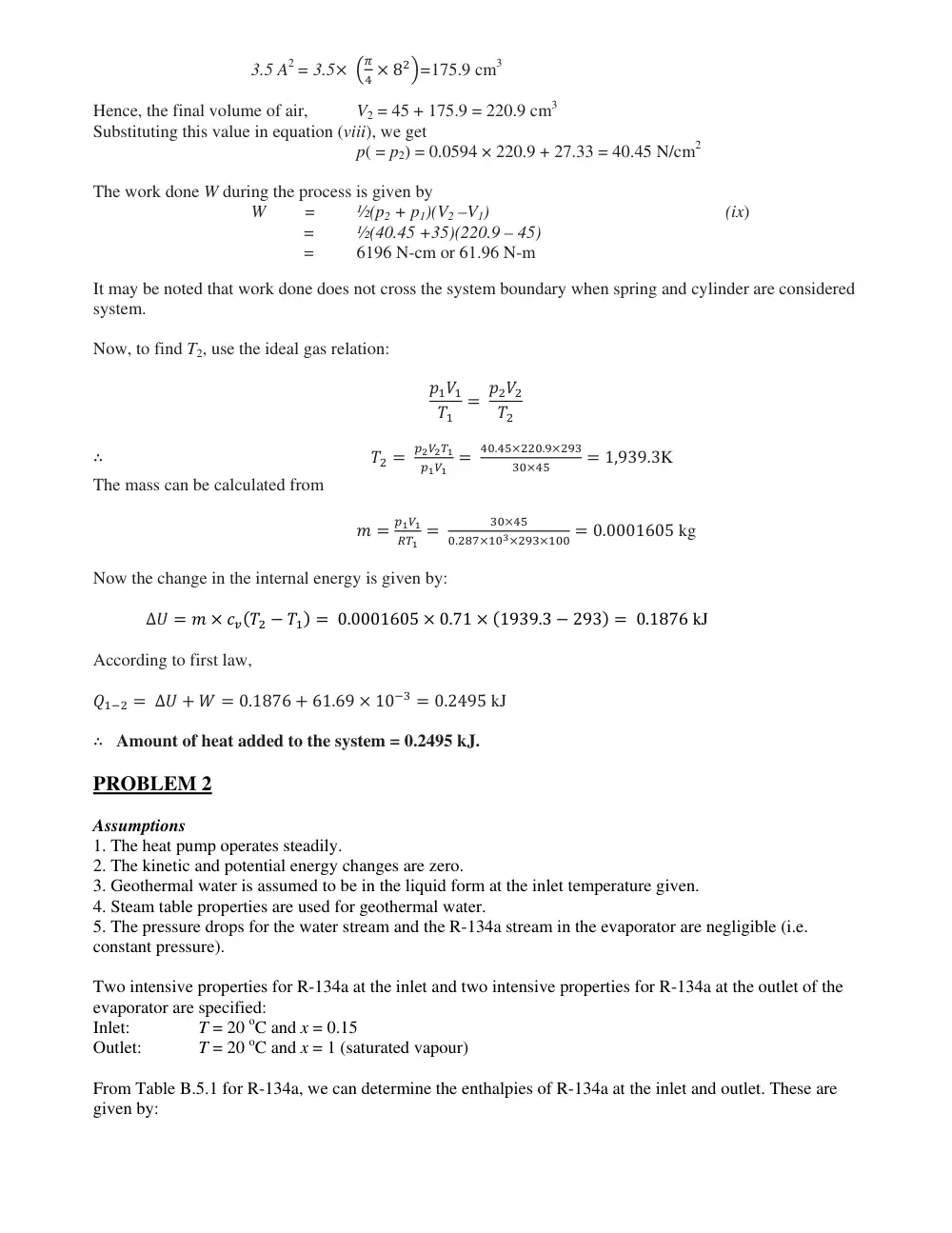
The work done W during the process is given by
W
=
½(p2 + p1)(V2 –V1)
(ix)
=
½(40.45 +35)(220.9 – 45)
=
6196 N-cm or 61.96 N-m
It may be noted that work done does not cross the system boundary when spring and cylinder are considered
system.
Now, to find T2, use the ideal gas relation:
����
��
� ����
��
� �� �
������
���� �
��.������.�����
�����
� 1,939.3K
The mass can be calculated from
� �
����
��� �
�����
�.��������������� � 0.0001605 kg
Now the change in the internal energy is given by:
∆� � � � ����� � ��� � 0.0001605 � 0.71 � �1939.3 � 293� � 0.1876 kJ
According to first law,
���� � ∆� � � � 0.1876 � 61.69 � 10�� � 0.2495 kJ
� Amount of heat added to the system = 0.2495 kJ.
PROBLEM 2
Assumptions
1. The heat pump operates steadily.
2. The kinetic and potential energy changes are zero.
3. Geothermal water is assumed to be in the liquid form at the inlet temperature given.
4. Steam table properties are used for geothermal water.
5. The pressure drops for the water stream and the R-134a stream in the evaporator are negligible (i.e.
constant pressure).
Two intensive properties for R-134a at the inlet and two intensive properties for R-134a at the outlet of the
evaporator are specified:
Inlet:
T = 20 oC and x = 0.15
Outlet:
T = 20 oC and x = 1 (saturated vapour)
From Table B.5.1 for R-134a, we can determine the enthalpies of R-134a at the inlet and outlet. These are
given by:
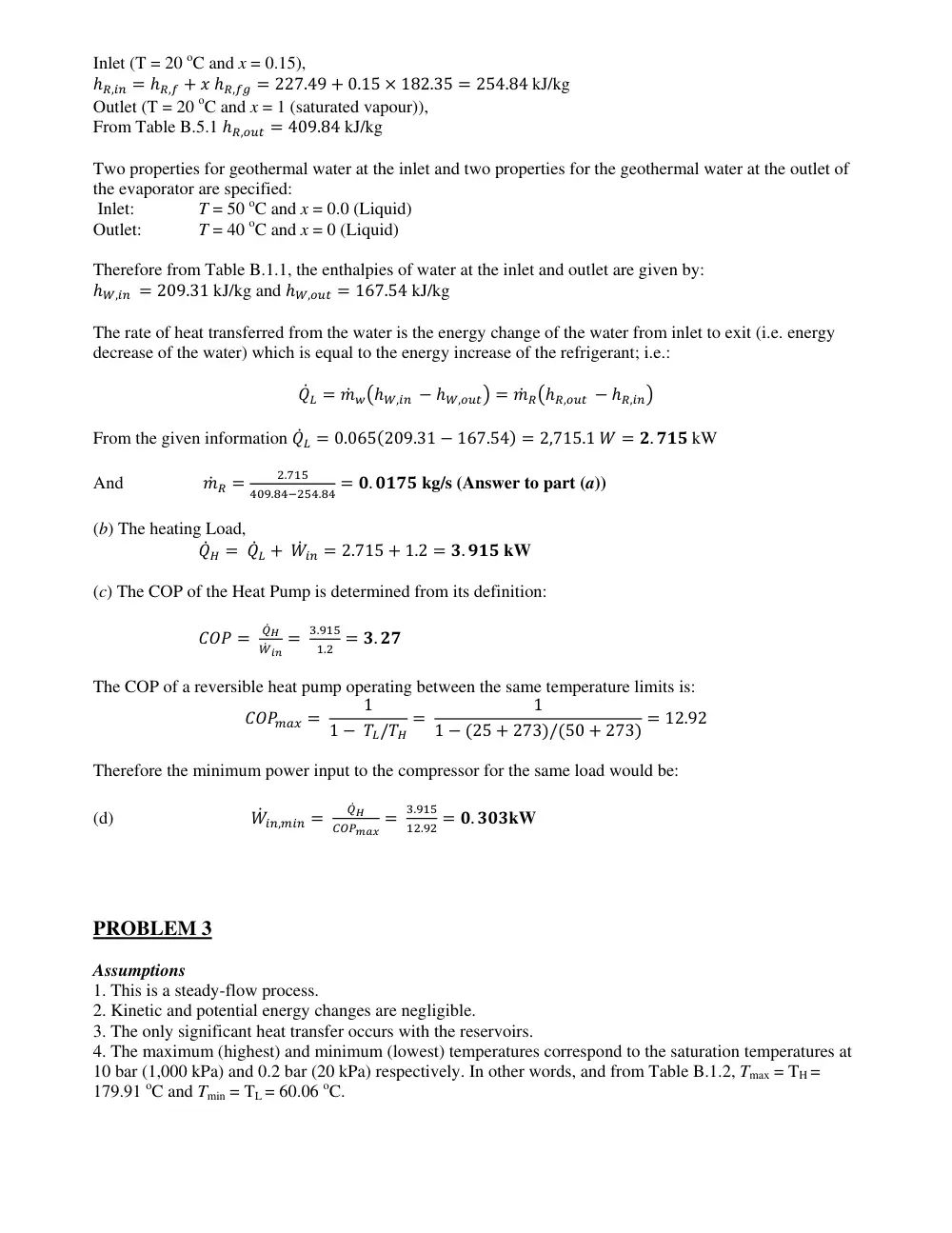
Inlet (T = 20 oC and x = 0.15),
��,�� � ��,� � � ��,�� � 227.49 � 0.15 � 182.35 � 254.84 kJ/kg
Outlet (T = 20 oC and x = 1 (saturated vapour)),
From Table B.5.1 ��,��� � 409.84 kJ/kg
Two properties for geothermal water at the inlet and two properties for the geothermal water at the outlet of
the evaporator are specified:
Inlet:
T = 50 oC and x = 0.0 (Liquid)
Outlet:
T = 40 oC and x = 0 (Liquid)
Therefore from Table B.1.1, the enthalpies of water at the inlet and outlet are given by:
��,�� � 209.31 kJ/kg and ��,��� � 167.54 kJ/kg
The rate of heat transferred from the water is the energy change of the water from inlet to exit (i.e. energy
decrease of the water) which is equal to the energy increase of the refrigerant; i.e.:
��� � �� ����,�� � ��,���� � �� ����,��� � ��,���
From the given information ��� � 0.065�209.31 � 167.54� � 2,715.1 � � �. ��� kW
And
�� � �
�.���
���.������.�� � �. ���� kg/s (Answer to part (a))
(b) The heating Load,
��� � ��� � �� �� � 2.715 � 1.2 � �. ��� kW
(c) The COP of the Heat Pump is determined from its definition:
��� �
���
�� �� �
�.���
�.� � �. ��
The COP of a reversible heat pump operating between the same temperature limits is:
������ �
1
1 � ��/��
�
1
1 � �25 � 273�/�50 � 273� � 12.92
Therefore the minimum power input to the compressor for the same load would be:
(d)
�� ��,��� �
���
������ �
�.���
��.�� � �. ���kW
PROBLEM 3
Assumptions
1. This is a steady-flow process.
2. Kinetic and potential energy changes are negligible.
3. The only significant heat transfer occurs with the reservoirs.
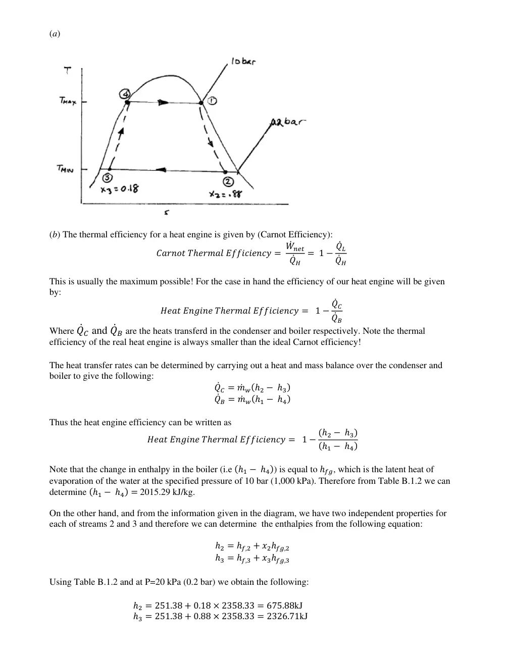
4. The maximum (highest) and minimum (lowest) temperatures correspond to the saturation temperatures at
10 bar (1,000 kPa) and 0.2 bar (20 kPa) respectively. In other words, and from Table B.1.2, Tmax = TH =
179.91 oC and Tmin = TL = 60.06 oC.
(a)
(b) The thermal efficiency for a heat engine is given by (Carnot Efficiency):
������ ������� ���������� � �� ���
���
� 1 � ���
���
This is usually the maximum possible! For the case in hand the efficiency of our heat engine will be given
by:
���� ������ ������� ���������� � 1 � ���
���
Where ��� and ��� are the heats transferd in the condenser and boiler respectively. Note the thermal
efficiency of the real heat engine is always smaller than the ideal Carnot efficiency!
The heat transfer rates can be determined by carrying out a heat and mass balance over the condenser and
boiler to give the following:
��� � �� ���� � ���
��� � �� ���� � ���
Thus the heat engine efficiency can be written as
���� ������ ������� ���������� � 1 � ��� � ���
��� � ���
Note that the change in enthalpy in the boiler (i.e ��� � ���) is equal to ���, which is the latent heat of
evaporation of the water at the specified pressure of 10 bar (1,000 kPa). Therefore from Table B.1.2 we can
determine ��� � ��� � 2015.29 kJ/kg.
On the other hand, and from the information given in the diagram, we have two independent properties for
each of streams 2 and 3 and therefore we can determine the enthalpies from the following equation:
�� � ��,� � �����,�
�� � ��,� � �����,�
Using Table B.1.2 and at P=20 kPa (0.2 bar) we obtain the following:
�� � 251.38 � 0.18 � 2358.33 � 675.88kJ
�� � 251.38 � 0.88 � 2358.33 � 2326.71kJ
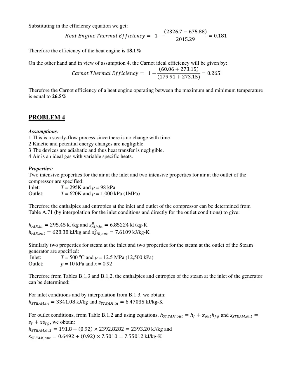
Substituting in the efficiency equation we get:
���� ������ ������� ���������� � 1 � �2326.7 � 675.88�
2015.29
� 0.181
Therefore the efficiency of the heat engine is 18.1%
On the other hand and in view of assumption 4, the Carnot ideal efficiency will be given by:
������ ������� ���������� � 1 � �60.06 � 273.15�
�179.91 � 273.15� � 0.265
Therefore the Carnot efficiency of a heat engine operating between the maximum and minimum temperature
is equal to 26.5%
PROBLEM 4
Assumptions:
1 This is a steady-flow process since there is no change with time.
2 Kinetic and potential energy changes are negligible.
3 The devices are adiabatic and thus heat transfer is negligible.
4 Air is an ideal gas with variable specific heats.
Properties:
Two intensive properties for the air at the inlet and two intensive properties for air at the outlet of the
compressor are specified:
Inlet:
T = 295K and p = 98 kPa
Outlet:
T = 620K and p = 1,000 kPa (1MPa)
Therefore the enthalpies and entropies at the inlet and outlet of the compressor can be determined from
Table A.71 (by interpolation for the inlet conditions and directly for the outlet conditions) to give:
����,�� � 295.45 kJ/kg and ����,��
�
� 6.85224 kJ/kg-K
����,��� � 628.38 kJ/kg and ����,���
�
� 7.6109 kJ/kg-K
Similarly two properties for steam at the inlet and two properties for the steam at the outlet of the Steam
generator are specified:
Inlet:
T = 500 oC and p = 12.5 MPa (12,500 kPa)
Outlet:
p = 10 kPa and x = 0.92
Therefore from Tables B.1.3 and B.1.2, the enthalpies and entropies of the steam at the inlet of the generator
can be determined:
For inlet conditions and by interpolation from B.1.3, we obtain:
������,�� � 3341.08 kJ/kg and ������,�� � 6.47035 kJ/kg-K
For outlet conditions, from Table B.1.2 and using equations, ������,��� � �� � ������� and ������,��� �
�� � ����, we obtain:
������,��� � 191.8 � �0.92� � 2392.8282 � 2393.20 kJ/kg and
������,��� � 0.6492 � �0.92� � 7.5010 � 7.55012 kJ/kg-K
There is only one inlet and one exit for either device, and thus �� �� � �� ��� � �� . We take either the steam
turbine or the compressor as the system, which is a control volume since mass crosses the boundary. The
energy balance for either steady-flow system can be expressed in the rate form:
���� � ����� � ∆�� where for steady state conditions ∆�� will be equal to zero; i.e. ���� � �����
Therefore for the turbine and compressor the energy balance equations will become:
Compressor:
�� ����������,�� � �� ��������,��� � ����,���
Turbine
�� �������,��� � �� ������������,�� � ������,����
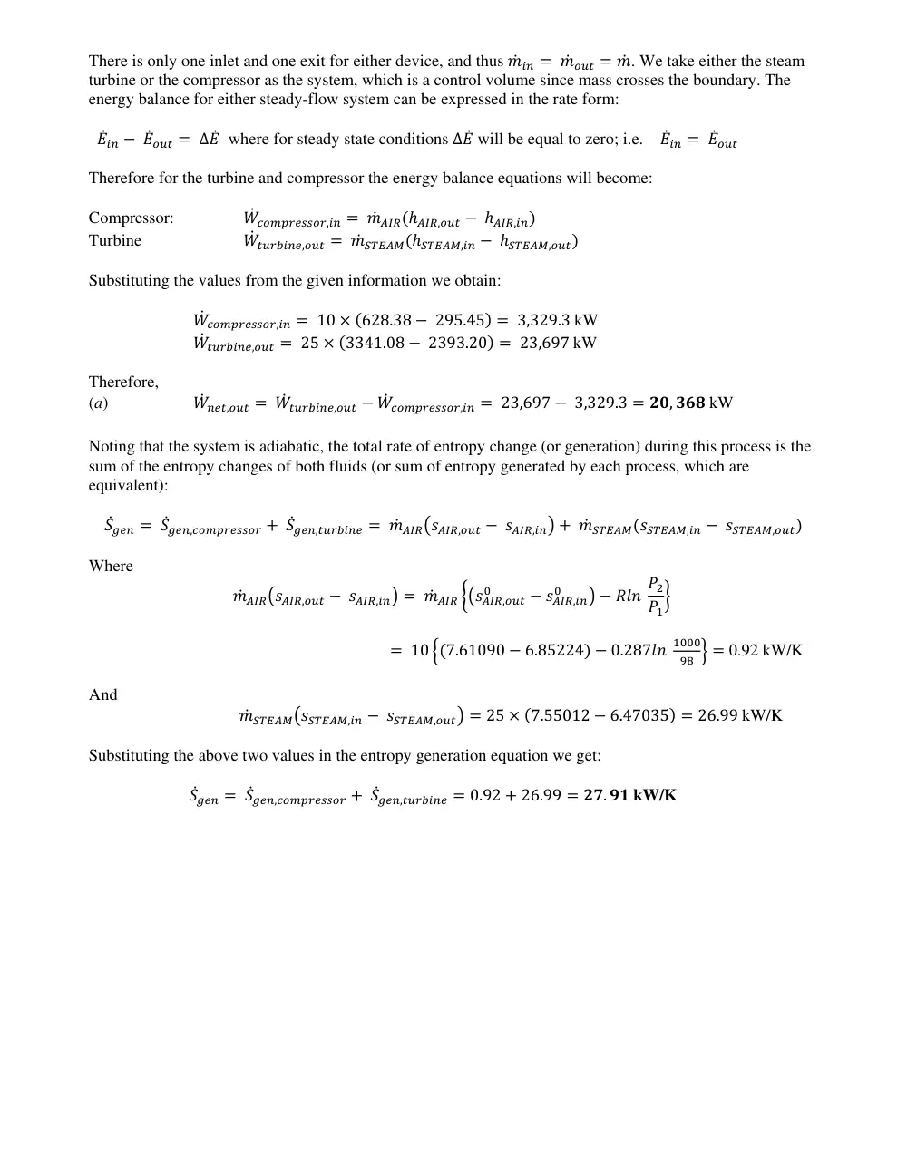
Substituting the values from the given information we obtain:
�� ����������,�� � 10 � �628.38 � 295.45� � 3,329.3 kW
�� �������,��� � 25 � �3341.08 � 2393.20� � 23,697 kW
Therefore,
(a)
�� ���,��� � �� �������,��� � �� ����������,�� � 23,697 � 3,329.3 � ��, ��� kW
Noting that the system is adiabatic, the total rate of entropy change (or generation) during this process is the
sum of the entropy changes of both fluids (or sum of entropy generated by each process, which are
equivalent):
����� � �����,���������� � �����,������� � �� ��������,��� � ����,��� � �� ������������,�� � ������,����
Where
�� ��������,��� � ����,��� � �� ��� ������,���
�
� ����,��
�
� � ��� ��
��
�
� 10 ��7.61090 � 6.85224� � 0.287��
����
�� � � 0.92 kW/K
And
�� ������������,�� � ������,���� � 25 � �7.55012 � 6.47035� � 26.99 kW/K
Substituting the above two values in the entropy generation equation we get:
����� � �����,���������� � �����,������� � 0.92 � 26.99 � ��. �� kW/K
PROBLEM 5
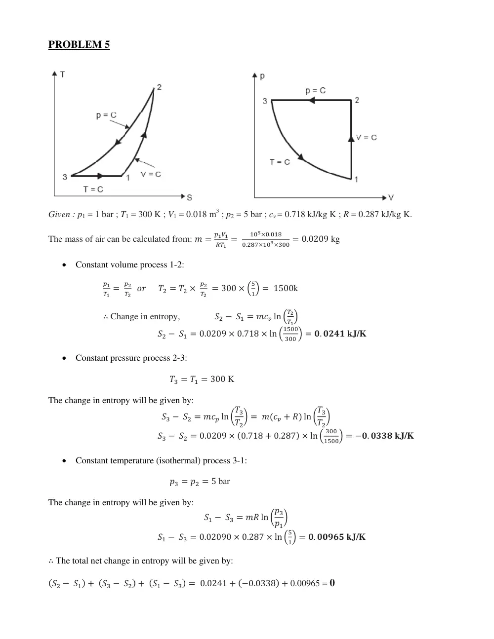
Given : p1 = 1 bar ; T1 = 300 K ; V1 = 0.018 m3 ; p2 = 5 bar ; cv = 0.718 kJ/kg K ; R = 0.287 kJ/kg K.
The mass of air can be calculated from: � �
����
��� �
�����.���
�.����������� � 0.0209 kg
• Constant volume process 1-2:
��
�� �
��
�� �� �� � �� �
��
�� � 300 � �
�
�� � 1500k
� Change in entropy,
�� � �� � ��� ln �
��
���
�� � �� � 0.0209 � 0.718 � ln �
����
��� � � �. ���� kJ/K
• Constant pressure process 2-3:
�� � �� � 300 K
The change in entropy will be given by:
�� � �� � ��� ln ���
��
� � ���� � �� ln ���
��
�
�� � �� � 0.0209 � �0.718 � 0.287� � ln �
���
����� � ��. ���� kJ/K
• Constant temperature (isothermal) process 3-1:
�� � �� � 5 bar
The change in entropy will be given by:
�� � �� � �� ln ���
��
�
�� � �� � 0.02090 � 0.287 � ln �
�
�� � �. ����� kJ/K
� The total net change in entropy will be given by:
��� � ��� � ��� � ��� � ��� � ��� � 0.0241 � ��0.0338� � 0.00965 = 0
BONUS PROBLEMS
BP1
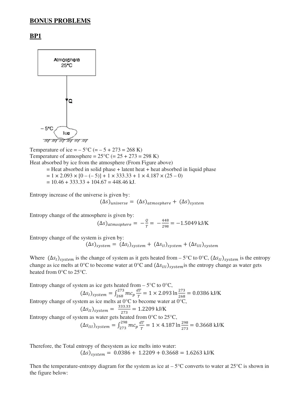
Temperature of ice = – 5°C (= – 5 + 273 = 268 K)
Temperature of atmosphere = 25°C (= 25 + 273 = 298 K)
Heat absorbed by ice from the atmosphere (From Figure above)
= Heat absorbed in solid phase + latent heat + heat absorbed in liquid phase
= 1 × 2.093 × [0 – (– 5)] + 1 × 333.33 + 1 × 4.187 × (25 – 0)
= 10.46 + 333.33 + 104.67 = 448.46 kJ.
Entropy increase of the universe is given by:
�∆���������� � �∆������������ � �∆��������
Entropy change of the atmosphere is given by:
�∆������������ � �
�
� � �
���
��� � �1.5049 kJ/K
Entropy change of the system is given by:
�∆�������� � �∆��������� � �∆���������� � �∆�����������
Where �∆��������� is the change of system as it gets heated from – 5°C to 0°C, �∆���������� is the entropy
change as ice melts at 0°C to become water at 0°C and �∆�����������is the entropy change as water gets
heated from 0°C to 25°C.
Entropy change of system as ice gets heated from – 5°C to 0°C,
�∆��������� � �
���
��
�
���
���
� 1 � 2.093 ln
���
��� � 0.0386 kJ/K
Entropy change of system as ice melts at 0°C to become water at 0°C,
�∆���������� �
���.��
��� � 1.2209 kJ/K
Entropy change of system as water gets heated from 0°C to 25°C,
�∆����������� � �
���
��
�
���
���
� 1 � 4.187 ln
���
��� � 0.3668 kJ/K
Therefore, the Total entropy of thesystem as ice melts into water:
�∆�������� � 0.0386 � 1.2209 � 0.3668 � 1.6263 kJ/K
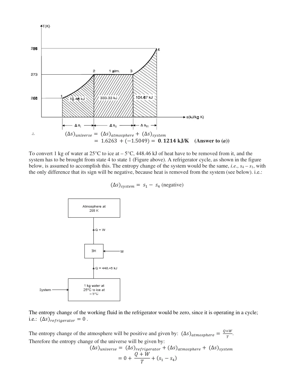
Then the temperature-entropy diagram for the system as ice at – 5°C converts to water at 25°C is shown in
the figure below:
� �∆���������� � �∆������������ � �∆��������
� 1.6263 � ��1.5049� � �. ���� kJ/K (Answer to (a))
To convert 1 kg of water at 25°C to ice at – 5°C, 448.46 kJ of heat have to be removed from it, and the
system has to be brought from state 4 to state 1 (Figure above). A refrigerator cycle, as shown in the figure
below, is assumed to accomplish this. The entropy change of the system would be the same, i.e., s4 – s1, with
the only difference that its sign will be negative, because heat is removed from the system (see below). i.e.:
�∆�������� � �� � �� (negative)
The entropy change of the working fluid in the refrigerator would be zero, since it is operating in a cycle;
i.e.: �∆�������������� � 0 .
The entropy change of the atmosphere will be positive and given by: �∆������������ �
���
� .
Therefore the entropy change of the universe will be given by:
�∆���������� � �∆�������������� � �∆������������ � �∆��������
� 0 � � � �
�
� ��� � ���
By the principle of increase of entropy:
�∆���������� � 0
� � � �
�
� ��� � ��� � 0
� � � �
�
� ��� � ���
� � ���� � ��� � �
���� � ���� � ��� � �
Where � � 448.46 kJ and � � 298K and ��� � ��� � 1.6263 kJ/K
Therefore:
� � 298 � 1.6263 � 448.46 � ��. �� kJ (Answer to (b))
BP2
Assumptions
1 The room is maintained at 20°C and 95 kPa at all times.
2 Air is an ideal gas with constant specific heats at room temperature.
3 The moisture is condensed at an average temperature of 4°C.
4 Half of the air volume in the refrigerator is replaced by the warmer kitchen air each time the door is
opened.
Properties:
The gas constant of air is R = 0.287 kPa.m3/kgK. The specific heat of air at room temperature is cp = 1.005
kJ/kg-k (Table A-5). The heat of vaporization of water at 4°C, i.e. hfg can be obtained from Table B.1.1 by
interpolation to be equal to 2492 kJ/kg .
The volume of the refrigerated air replaced each time the refrigerator is opened is 0.3 m3 (half of the 0.6 m3
air volume in the refrigerator). Then the total volume of refrigerated air replaced by room air per year is
The density of air at the refrigerated space conditions of 95 kPa and 4oC and the mass of air replaced per
year are:
The amount of moisture condensed and removed by the refrigerator is