
PHY 233 Final, Spring 2010
Haigazian University · Digital Electronics · 2 pages

More PHY 233 files
Show the text of this final exam
eR SE
roe meepgarepar 5
BLU. Spring 2009 Name: orate MARSTON MATRON Tae HGP NET
PHY233
FINAL
Notes:
1. You can save considerable time if you answer parts of questions
2, 3, 4, 5, 6, 7f, and 7g on the question sheet itself.
2. Cellular phones and programmable calculators must be stashed
out of sight, as you will use neither .
1, Use D Flip Flops to realize the state machine for the state transition
diagram shown by the One-Hot method.
(No points for other methods) (12 pts.)
AB
2. The Karnaugh map shown is that of an Asynchronous State machine. cDy. 00 Of 11 19
; 00 ae oe
a Circle the stable states (1 pts.)
b. Identify Oscillations (3 pts.)
©) Identify Critical Races (4 pts.)
3. The figure shows a state transition diagram and a blank Implication chart.
a. Mark the vertical axis and fill the chart. (5 pts.)
b. Argue that there is no obvious state minimization (2 pts.)
c. Can you draw the minimized 2-state diagram? (3 pts.) .
4. The figures shows two sequences. The initial state is
shown in the first coloumn of the timing diagram
below (a, a, x = y = 0). Fill the timing diagram until
you observe that a pattern is being repeated.
You may extend the time axis of the diagram if you
find it necessary. (10 pts.)
oud a edudchodndaae
Peper ret
a
a EEO Poppe
oP PEEP re
5. The figure shows the truth table of the NAND and the assignment 2 Opel
map for the states (a,b,c,&d ). x
33 ‘ 3X x .
a. Identify the states on the State Transition Diagram. (8 pts.) i cal A
Uijo] ide} LC XS bb)
Give 2 reasons why can’t this “machine” cannot be used “2 pts.)
mS
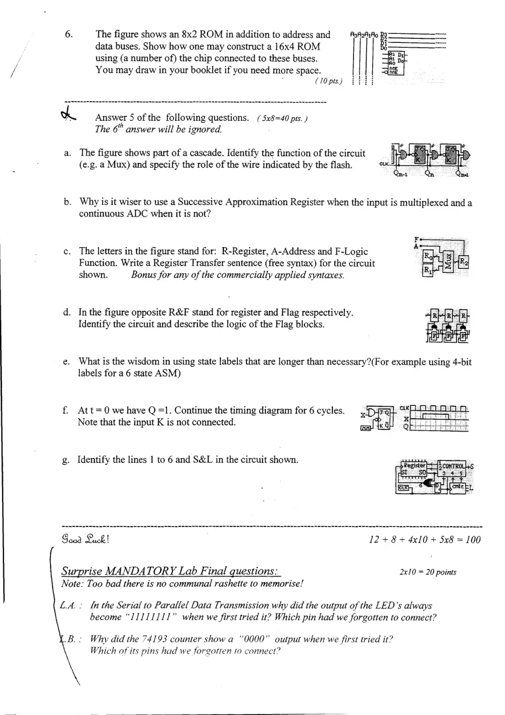
6. The figure shows an 8x2 ROM in addition to address and —AsA2AuFto Bs
data buses. Show how one may construct a 16x4 ROM | | Bd
using (a number of) the chip connected to these buses.
You may draw in your booklet if you need more space.
. (10 pts.)
A Answer 5 of the following questions. ( 5x8=40 prs. )
The 6" answer will be ignored.
a. The figure shows part of a cascade. Identify the function of the circuit
(e.g. a Mux) and specify the role of the wire indicated by the flash.
b. Why is it wiser to use a Successive Approximation Register when the input is multiplexed and a
continuous ADC when it is not?
c. The letters in the figure stand for: R-Register, A-Address and F-Logic
Function. Write a Register Transfer sentence (free syntax) for the circuit
shown. Bonus for any of the commercially applied syntaxes.
d. In the figure opposite R&F stand for register and Flag respectively.
Identify the circuit and describe the logic of the Flag blocks.
e. What is the wisdom in using state labels that are longer than necessary?(For example using 4-bit
labels for a 6 state ASM)
f. Att=0 we have Q =1. Continue the timing diagram for 6 cycles.
Note that the input K is not connected.
g. Identify the lines 1 to 6 and S&L in the circuit shown.
Good Luck! 12+ 8+ 4x10 + 5x8 = 100
J
Surprise MANDATORY Lab Final questions: 2x10 = 20 points
Note: Too bad there is no communal rashette to memorise!
L.A. : ta the Serial to Parallel Data Transmission why did the output of the LED’s always
become “11111111” when we first tried it? Which pin had we forgotten to connect?
Why did the 74193 counter show a “0000” output when we first tried it?
Which of its pins had we forgotten to connect?