
PHY 233 Lab Final, Spring 2011
Haigazian University · Digital Electronics · 2 pages

More PHY 233 files
Show the text of this final exam
so
H.U. Spring 2009 Name: -----------------------
c
PHY 233 Lab Final
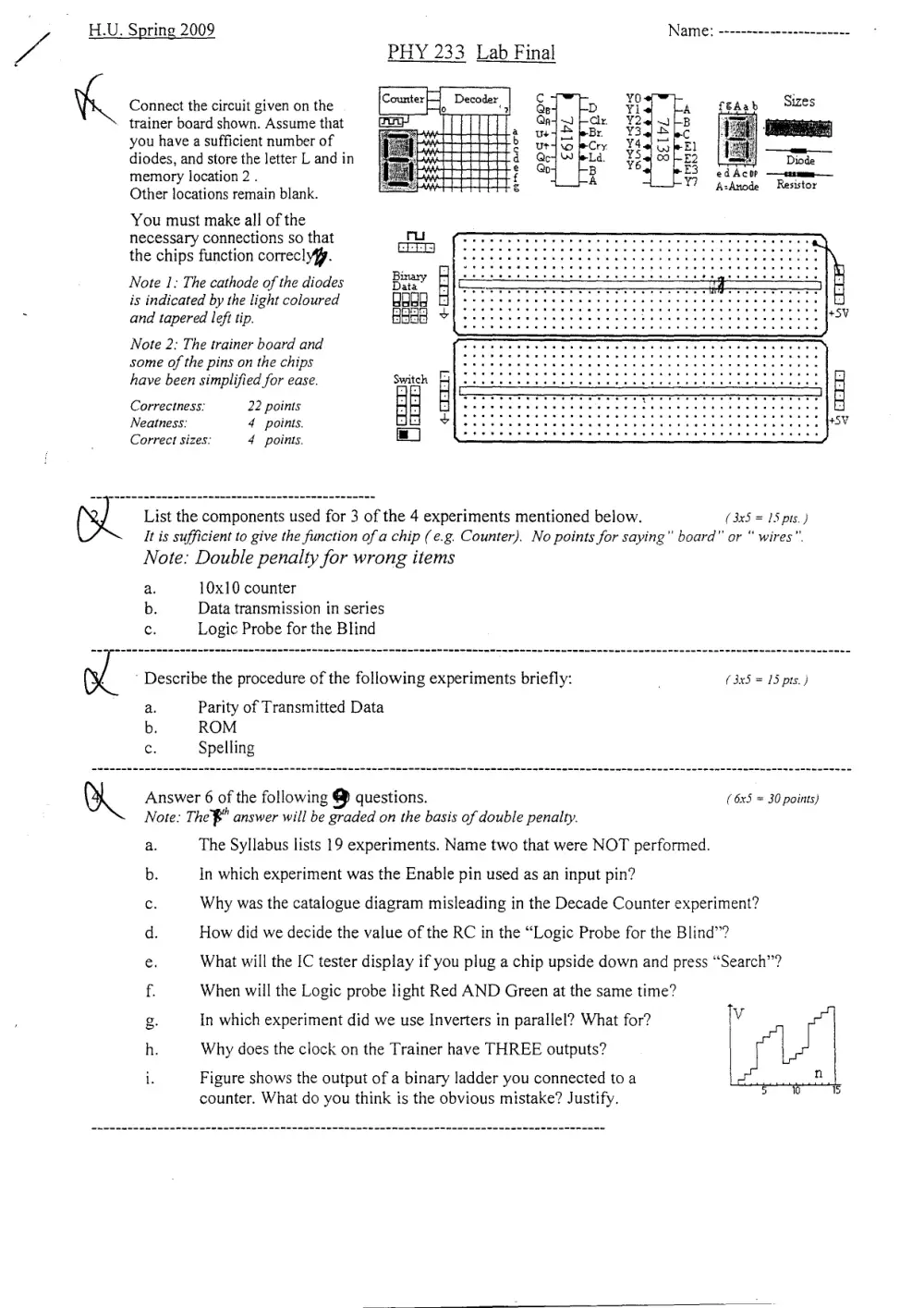
Connect the circuit given on the Counter, Decoder, | ee dn + A
trainer board shown. Assume that eat Gj Er F208
: a oud Br Y3q45 bc
you have a sufficient number of Ec wenn bud leCry: ¥4e Se El
diodes, and store the letter L and in ‘ d Ge w a % oo B
i i KAW o edAco? ——t2smm—
memory location 2 . et £ ra Y? fcancde Restor
Other locations remain blank.
You must make all of the
necessary connections so that
the chips function correclyfy.
Note 1: The cathode of the diodes
is indicated by the light coloured
and tapered left tip.
Note 2: The trainer board and
some of the pins on the chips
have been simplified for ease.
Correctness: 22 points
Neatness: 4 points.
Correct sizes: 4 points.
List the components used for 3 of the 4 experiments mentioned below. (3x5 = 15 pis.)
Be It is sufficient to give the function of a chip (e.g. Counter). No points for saying” board” or “ wires”.
Note: Double penalty for wrong items
a. 10x10 counter
b. Data transmission in series
Ss Logic Probe for the Blind
’ Describe the procedure of the following experiments briefly: ; (3x5 = 15 pts.)
a. Parity of Transmitted Data
b. ROM
Gs Spelling
Answer 6 of the following g questions. (6x5 = 30 points)
Note: The" answer will be graded on the basis of double penalty.
The Syllabus lists 19 experiments. Name two that were NOT performed.
Ss 2
In which experiment was the Enable pin used as an input pin?
Why was the catalogue diagram misleading in the Decade Counter experiment?
How did we decide the value of the RC in the “Logic Probe for the Blind”?
a 9
What will the IC tester display if you plug a chip upside down and press “Search’’?
When will the Logic probe light Red AND Green at the same time?
In which experiment did we use Inverters in parallel? What for? v
Why does the clock on the Trainer have THREE outputs?
x mm o
i. Figure shows the output of a binary ladder you connected to a
counter. What do you think is the obvious mistake? Justify.
Page 2
gE You are given a list of 8 malfunctions and a list of 14 possible causes.
For 5 of the malfunctions Indicate next to each “trouble” the likely cause or causes.
Explain your answer briefly. No explanation, no points.
Note: Answers beyond 6 will be corrected on the basis of double penalty. (3x5 = 15 pis.)
Causes: Cl. Power Supply on Trainer board does not give exactly 5v
C2. Chip plugged backwards
C3. Wrong chip plugged in
C4. — Vee pin shorted to ground
CS. Chip plugged between two breadboards
C6. = Vee pin not connected
C7. Two output or input pins are interchanged
C8. Clock at wrong speed (specify whether too fast or too slow)
C9. A wire is loose or internally broken
C10. A pin on the chip folded while plugging
Cll Chip burnt
C12. Ground pin not connected
C13. Chip has a broken pin
C14. Clock has a weak or bad signal
Malfunctions:
a. Seven segment LED shows “Karshoni”’ characters.
b. Pilot light on Trainer Board turns off when you connect the circuit
C. Chip too hot
d. One of the pins on a chip is neither high nor low
e. All the pins of a chip are high.
f Chip works only when you press it down by a finger
g. An LED output is lights dimly (not clearly on or off)
h. All the LED outputs of a counter are on and seem to “flicker”
Good Luck! 2X30 + 3X15 = 105