
CHEN 490 Notes, Fall 2016
American University of Beirut · Fundamentals of Petroleum Engineering · 18 pages
Showing the first 10 of 18 pages. Download the PDF to see all of it.
More CHEN 490 files
- Notes Midterm Notes (Complete) · Fall 2014NotesView
- Notes Logging (Final) · Fall 2014Final examView
- Notes Drilling Notes(Final) · Fall 2014Final examView
- Notes Final Outline · Fall 2014Final examView
- Notes Flow Equations (Final) · Fall 2014Final examView
- Notes Resevoir Engineering (Final) · Fall 2014Final examView
- Notes Rotary Drilling Hydraulics (Final) · Fall 2014Final examView
- Notes Log Examples (Final) · Fall 2014Final examView
Show the text of this notes
COURSE OUTCOMES:
-
Know the nature of petroleum, and describe the oil and gas supply chain. –
-
Know the concepts of petroleum geology and basic rock properties, and the
mechanisms of the “Petroleum System”.
-
Describe drilling operations, equipment, and the general basic drilling techniques and
systems.
-
Know the composition, functions, and nature of rotary drilling fluids.
-
Know the well completion methods, casing strings, tubing and packer.
-
Know the general coring methods, core type, equipment and operational procedures.
Handling the sampling of core recovery.
-
Know well logging basic concept and purpose, types and the miscellaneous logging
devices.
-
Be able to know what causes the formation damage and well treatment.
-
Know the geologic types of reservoirs and their drive mechanisms.
-
To be able to estimate the hydrocarbon in place and reserves.
-
Differentiate between Petroleum fiscal systems and have an introductory understanding
of the Lebanese Petroleum Fiscal System.
NOTES:
-
Sedimentary rocks are the most common reservoir rocks because they are more porous
than igneous and metamorphic rocks. Also, sedimentary rocks form under temperatures
and pressures at which hydrocarbons may be preserved.
-
Porosity = (total rock volume – rock grain volume) / total rock volume. It is the fraction
of the rock’s volume that consists of pores.
-
Permeability is a measure of the ease at which a fluid can flow through a rock.
-
Petroleum is a mixture of many hydrocarbons (paraffin hydrocarbons, cycloparaffins,
aromatic hydrocarbons, polynuclear hydrocarbons + S,N,O,Metals as impurities).
-
Fluid Mixture can be vapor, liquid or two-phase (both).
-
Compressing gas produces liquid. Expanding liquid produces gas.
-
Bubble Point: point at which first bubble of gas appears.
-
Dew Point: point at which first drop of liquid appears.
-
Fluids (black oil, volatile oil, wet gas, dry gas, gas condensate).
-
Pressure decreases as we move through the production system (Reservoir, wellbore,
separator).
-
Oil comes from:
Liquid: free oil
Vapor: vaporized oil
-
Gas comes from:
Liquid: dissolved gas
Vapor: free gas
-
Hydrocarbon pathway: EXPLORATION (Explore – Appraise) – DEVELOPMENT (Concept –
Design – Execute) – PRODUCTION (Execute – Optimize)
-
Exploration: How do we make economically sound decisions about where to drill? How
do you predict the presence of petroleum? Where does petroleum come from?
-
Appraisal/Delineation: How much oil or gas is there?
-
Development: Select and execute optimal development plan/How much could we
produce? / How much is feasible to produce?
-
Operation and Production Optimization: Field Management, Stimulation and Enhanced
oil recovery.
-
Upstream: Onshore/offshore rig
-
Mid-stream: Transportation
-
Downstream: Refineries
-
First phase: We invest a lot of money and we pay a lot. Second phase: we start earning
money.
-
Pre-production (Exploration/Appraisal/Delineation) – Build Up (development) – Plateau
(Reservoir management/Production operations/Primary recovery) – Decline (Enhanced
recovery/Secondary recovery/Tertiary recovery) – Abandonment.
-
Storage facilities are important to control supply and demand and to maintain the
quality of the produced hydrocarbons.
-
OIL: Production (drilling, extraction and recovery) – Storage – Export – Transport –
Refine – Terminal - Sell.
-
GAS: Processing Plant – Regasification – Underground Storage – Fractionator –
Liquification – Export.
-
Theories on the origin of oil and gas:
a) Inorganic Theory (abiogenic)
b) Organic Theory (biogenic)
-
Oil and gas are lighter than water. They are pushed upwards onto the surface by the
water.
-
Reservoir rocks are usually sandstone or limestone.
-
A conventional Petroleum System requires four components:
a) Source rock
b) Reservoir rock
c) Trap
d) Seal
-
A conventional Petroleum System requires two processes:
a) Petroleum generation
b) Petroleum migration
-
Timing between petroleum migration and creation of the reservoir, trap and seal is
critical.
-
Structural Traps: Anticlines – Faults.
-
Stratigraphic Traps: Angular unconformities – Reefs – Pinchout.
-
Salt domes
-
Organic Matter in Sedimentary rocks is either “Bitumen” (organic constituent of fine-
grained sedimentary rocks that is fusible and soluble in common organic solvents) or
“Kerogen” (organic constituent of sedimentary rocks that is not soluble in common
organic solvents).
-
Petroleum System Maturity is the state of the source rock with respect to its ability to
generate oil or gas.
-
An oil-prone source rock matures to produce heavy medium light oils.
-
At T > 100 degrees C dry gas
-
The generation of hydrocarbons in source rocks is controlled by the temperature as
kerogen transforms from reactive to dead carbon.
-
Diagenesis (gas), Catagenesis (oil and gas), Metagenesis (any remaining oil + simpler
forms of dry gas). Process varies with the type of kerogen.
-
65 degrees C for oil generation, above 150 degrees C we only have natural gas, above
250 degrees C we get carbon.
-
The temperature should not be too low (no generation) or too high (carbonized).
-
Trap should form before generation, migration and accumulation. Critical moment could
be halfway through generation, migration and accumulation.
-
Nonhydrocarbon gases Oil Wet gas Dry gas
-
Primary Migration: expulsion of newly generated hydrocarbons from a source rock.
-
Secondary Migration: movement of hydrocarbons into reservoir rock in a trap or other
area of accumulation.
-
When late generation occurs, gas displaces oil and the displaced oil accumulates in one
area.
-
Sandstones have high permeability thus allow fluid flow easily.
-
Migrating hydrocarbons can either find their way to the surface and create seeps or
become trapped in porous reservoir rock. Because of migration, oil and gas end up
accumulating far from their source.
-
Source System Carrier System Reservoir System
-
Trap must be available before or during migration.
-
Thermal maturation of kerogen depends linearly on time and exponentially on
temperature.
-
Source rock: continuously expels petroleum when active (could be active, inactive or
spent). Should be fine-grained and rich with organic matter. Amount of HC released
depends on the rock volume and thermal maturity.
-
Reservoir rock: permits the migration and accumulation of petroleum under adequate
trap conditions.
-
Seal/Trap: can withstand capillary pressure and prevents the further migration of
hydrocarbons in the subsurface.
-
Overburden rock: overlies the source rock and contributes to its thermal maturation.
-
High Hydrogen/Carbon ratio Oil / Low Hydrogen/Carbon ratio Gas
-
The amount of HC generated depends on the kerogen type and the heating rate.
-
Biodegradation (biogenic/abiogenic) affects crude oil quality. Occurs at T < 80 degrees C
at oil-water contacts.
-
Types of rock: Igneous (Molten materials; Crystallization) – Sedimentary (Weathering
and erosion of rocks at the surface; Sedimentation, Burial and lithification) –
Metamorphic (Rocks under high T and P; Recrystallization due to heat, pressure or
chemically active fluids).
-
Sedimentary rocks are the most important rocks for the oil industry. They can be clastic
(from erosion) or chemical (through chemical or biological processes).
-
Clastic Rocks: Sand – Silt – Clay. The difference lies in the size of the grain.
-
Depositional Environments can be Marine (sea) / Lake / Continental / Shallow or deep
water.
-
Grains from carbonate rocks are deposited close to where they formed. On the other
hand, grains from sand and silt travel far away from their source before they deposit.
-
Porosity of Carbonate Rocks: Connected – Vugs – Fracture Porosity
-
Oil can adhere to the surface of carbonate rocks because of wettability (thus harder to
produce).
-
Most carbonate reservoirs are believed to have mixed wettability or be oil-wet.
Sandstone are only water-wet.
-
Carbonates exhibit highly variant properties (porosity, permeability, flow mechanisms)
within small sections of the reservoir. This makes them difficult to characterize.
-
Anticlines, faults and salt domes give evidence of the presence of hydrocarbons.
-
Wellbore data: Information gathered from wells that have been already drilled.
-
Cuttings: emerge as the well is drilled. These can be analyzed to obtain important
information.
-
Logging: lower a tool down into the well to take electrical and other kinds of
measurements (porosity, permeability and absence/presence of hydrocarbons and
quantity).
-
Gravity Method: sense the difference in gravitational pull due to change in density of
the rocks.
-
Magnetic Method: detects changes in magnetic field.
-
Seismic Method: generates an acoustic pulse at the surface using a source such as a
vibrator truck, explosives or an air gun (in marine seismic).
-
Basin: Large geographic area that may contain multiple hydrocarbon systems.
-
Play: Regionally – extensive unit with a single hydrocarbon system. Defined by geologic
boundaries.
-
Effective porosity: connected porosity that can contribute to production.
-
Wettability: Tendency of a fluid to spread on or to adhere to a solid surface in the
presence of other immiscible fluids.
-
Surface Tension: Interaction between hydrocarbons and water depends on the surface
tension between them. It is the film that separates two immiscible fluids.
-
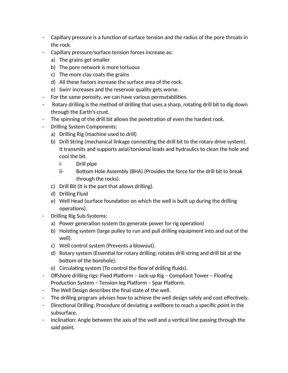
Capillary pressure is a function of surface tension and the radius of the pore throats in
the rock.
-
Capillary pressure/surface tension forces increase as:
a) The grains get smaller
b) The pore network is more tortuous
c) The more clay coats the grains
d) All these factors increase the surface area of the rock.
e) Swirr increases and the reservoir quality gets worse.
-
For the same porosity, we can have various permutabilities.
-
Rotary drilling is the method of drilling that uses a sharp, rotating drill bit to dig down
through the Earth’s crust.
-
The spinning of the drill bit allows the penetration of even the hardest rock.
-
Drilling System Components:
a) Drilling Rig (machine used to drill)
b) Drill String (mechanical linkage connecting the drill bit to the rotary drive system).
It transmits and supports axial/torsional loads and hydraulics to clean the hole and
cool the bit.
i-
Drill pipe
ii-
Bottom Hole Assembly (BHA) (Provides the force for the drill bit to break
through the rocks).
c) Drill Bit (It is the part that allows drilling).
d) Drilling Fluid
e) Well Head (surface foundation on which the well is built up during the drilling
operations).
-
Drilling Rig Sub-Systems:
a) Power generation system (to generate power for rig operation)
b) Hoisting system (large pulley to run and pull drilling equipment into and out of the
well).
c) Well control system (Prevents a blowout).
d) Rotary system (Essential for rotary drilling; rotates drill string and drill bit at the
bottom of the borehole).
e) Circulating system (To control the flow of drilling fluids).
-
Offshore drilling rigs: Fixed Platform – Jack-up Rig – Compliant Tower – Floating
Production System – Tension-leg Platform – Spar Platform.
-
The Well Design describes the final state of the well.
-
The drilling program advises how to achieve the well design safely and cost effectively.
-
Directional Drilling: Procedure of deviating a wellbore to reach a specific point in the
subsurface.
-
Inclination: Angle between the axis of the well and a vertical line passing through the
said point.
-
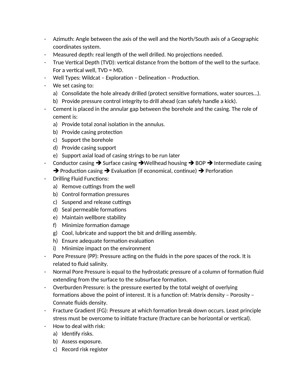
Azimuth: Angle between the axis of the well and the North/South axis of a Geographic
coordinates system.
-
Measured depth: real length of the well drilled. No projections needed.
-
True Vertical Depth (TVD): vertical distance from the bottom of the well to the surface.
For a vertical well, TVD = MD.
-
Well Types: Wildcat – Exploration – Delineation – Production.
-
We set casing to:
a) Consolidate the hole already drilled (protect sensitive formations, water sources…).
b) Provide pressure control integrity to drill ahead (can safely handle a kick).
-
Cement is placed in the annular gap between the borehole and the casing. The role of
cement is:
a) Provide total zonal isolation in the annulus.
b) Provide casing protection
c) Support the borehole
d) Provide casing support
e) Support axial load of casing strings to be run later
-
Conductor casing Surface casing Wellhead housing BOP Intermediate casing
Production casing Evaluation (if economical, continue) Perforation
-
Drilling Fluid Functions:
a) Remove cuttings from the well
b) Control formation pressures
c) Suspend and release cuttings
d) Seal permeable formations
e) Maintain wellbore stability
f)
Minimize formation damage
g) Cool, lubricate and support the bit and drilling assembly.
h) Ensure adequate formation evaluation
i)
Minimize impact on the environment
-
Pore Pressure (PP): Pressure acting on the fluids in the pore spaces of the rock. It is
related to fluid salinity.
-
Normal Pore Pressure is equal to the hydrostatic pressure of a column of formation fluid
extending from the surface to the subsurface formation.
-
Overburden Pressure: is the pressure exerted by the total weight of overlying
formations above the point of interest. It is a function of: Matrix density – Porosity –
Connate fluids density.
-
Fracture Gradient (FG): Pressure at which formation break down occurs. Least principle
stress must be overcome to initiate fracture (fracture can be horizontal or vertical).
-
How to deal with risk:
a) Identify risks.
b) Assess exposure.
c) Record risk register
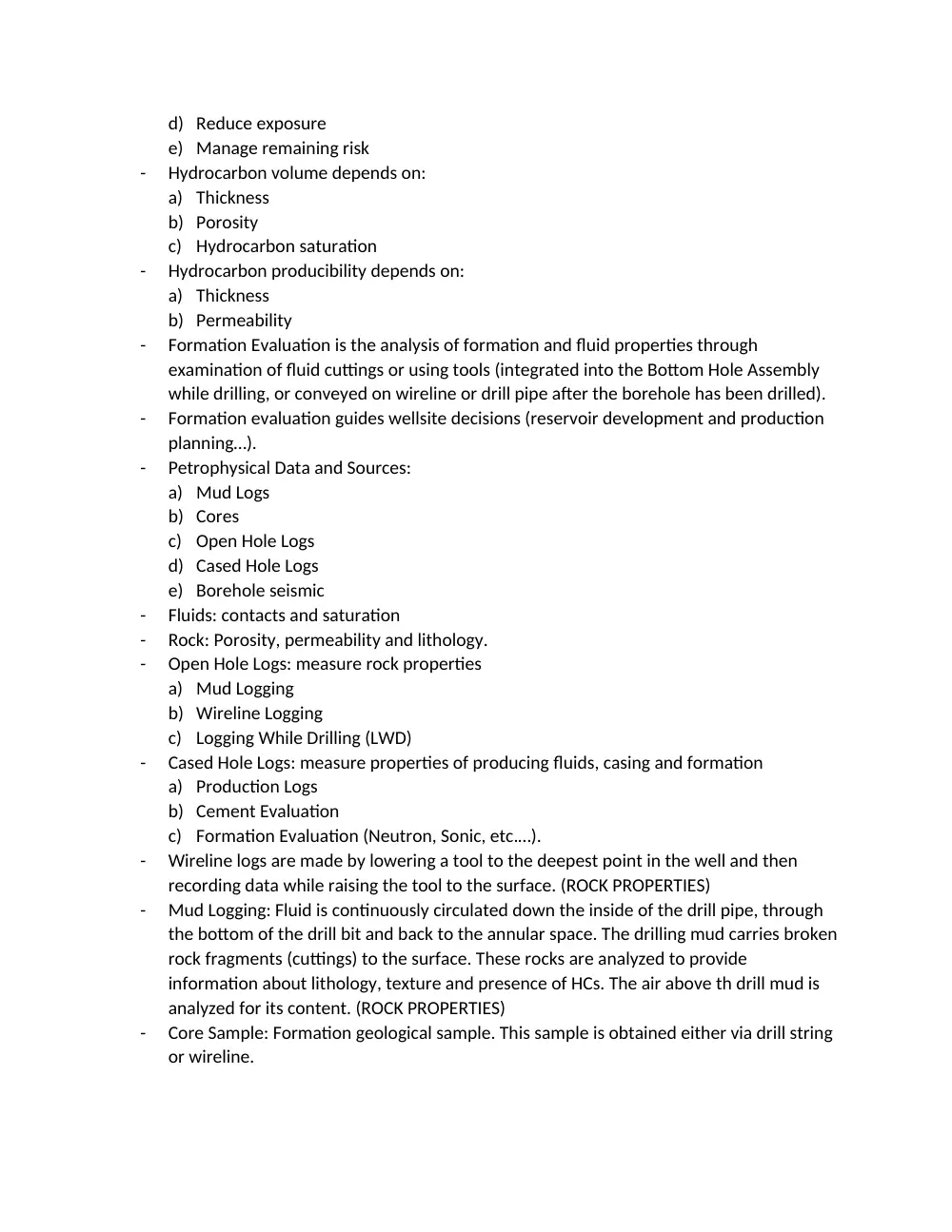
d) Reduce exposure
e) Manage remaining risk
-
Hydrocarbon volume depends on:
a) Thickness
b) Porosity
c) Hydrocarbon saturation
-
Hydrocarbon producibility depends on:
a) Thickness
b) Permeability
-
Formation Evaluation is the analysis of formation and fluid properties through
examination of fluid cuttings or using tools (integrated into the Bottom Hole Assembly
while drilling, or conveyed on wireline or drill pipe after the borehole has been drilled).
-
Formation evaluation guides wellsite decisions (reservoir development and production
planning…).
-
Petrophysical Data and Sources:
a) Mud Logs
b) Cores
c) Open Hole Logs
d) Cased Hole Logs
e) Borehole seismic
-
Fluids: contacts and saturation
-
Rock: Porosity, permeability and lithology.
-
Open Hole Logs: measure rock properties
a) Mud Logging
b) Wireline Logging
c) Logging While Drilling (LWD)
-
Cased Hole Logs: measure properties of producing fluids, casing and formation
a) Production Logs
b) Cement Evaluation
c) Formation Evaluation (Neutron, Sonic, etc.…).
-
Wireline logs are made by lowering a tool to the deepest point in the well and then
recording data while raising the tool to the surface. (ROCK PROPERTIES)
-
Mud Logging: Fluid is continuously circulated down the inside of the drill pipe, through
the bottom of the drill bit and back to the annular space. The drilling mud carries broken
rock fragments (cuttings) to the surface. These rocks are analyzed to provide
information about lithology, texture and presence of HCs. The air above th drill mud is
analyzed for its content. (ROCK PROPERTIES)
-
Core Sample: Formation geological sample. This sample is obtained either via drill string
or wireline.
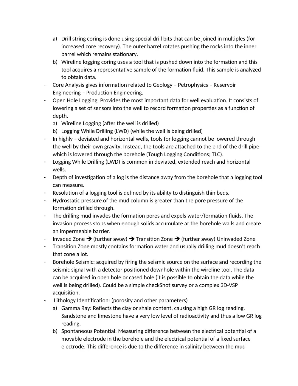
a) Drill string coring is done using special drill bits that can be joined in multiples (for
increased core recovery). The outer barrel rotates pushing the rocks into the inner
barrel which remains stationary.
b) Wireline logging coring uses a tool that is pushed down into the formation and this
tool acquires a representative sample of the formation fluid. This sample is analyzed
to obtain data.
-
Core Analysis gives information related to Geology – Petrophysics – Reservoir
Engineering – Production Engineering.
-
Open Hole Logging: Provides the most important data for well evaluation. It consists of
lowering a set of sensors into the well to record formation properties as a function of
depth.
a) Wireline Logging (after the well is drilled)
b) Logging While Drilling (LWD) (while the well is being drilled)
-
In highly – deviated and horizontal wells, tools for logging cannot be lowered through
the well by their own gravity. Instead, the tools are attached to the end of the drill pipe
which is lowered through the borehole (Tough Logging Conditions; TLC).
-
Logging While Drilling (LWD) is common in deviated, extended reach and horizontal
wells.
-
Depth of investigation of a log is the distance away from the borehole that a logging tool
can measure.
-
Resolution of a logging tool is defined by its ability to distinguish thin beds.
-
Hydrostatic pressure of the mud column is greater than the pore pressure of the
formation drilled through.
-
The drilling mud invades the formation pores and expels water/formation fluids. The
invasion process stops when enough solids accumulate at the borehole walls and create
an impermeable barrier.
-
Invaded Zone (further away) Transition Zone (further away) Uninvaded Zone
-
Transition Zone mostly contains formation water and usually drilling mud doesn’t reach
that zone a lot.
-
Borehole Seismic: acquired by firing the seismic source on the surface and recording the
seismic signal with a detector positioned downhole within the wireline tool. The data
can be acquired in open hole or cased hole (it is possible to obtain the data while the
well is being drilled). Could be a simple checkShot survey or a complex 3D-VSP
acquisition.
-
Lithology Identification: (porosity and other parameters)
a) Gamma Ray: Reflects the clay or shale content, causing a high GR log reading.
Sandstone and limestone have a very low level of radioactivity and thus a low GR log
reading.
b) Spontaneous Potential: Measuring difference between the electrical potential of a
movable electrode in the borehole and the electrical potential of a fixed surface
electrode. This difference is due to the difference in salinity between the mud
filtrate and the formation water. The SP log cannot be recorded when a well is
drilled using oil-based mud. Shale zones Straight line / Sand zones Not straight
line. SP log deflects to left in sand and to the right in shale
-
Check-Shot survey is used to determine the depth to time relationship.
-
Surface seismic data suffers due to low resolution.
-
Vertical Seismic Profile (VSP) is used to improve the resolution of surface seismic.
-
Porosity:
a) Sonic: measures formation slowness. Can be converted to porosity if matrix and fluid
slowness are known. Consists of a sound pulse and a receiver. These waves are
transformed to graphs as they impinge on the borehole wall. Records vs depth of the
time needed for the sound wave to travel 1ft of the formation. (shales cause
computed porosity to read high due to pressure of bound water / Oil and water have
little effect / gas causes the interval transit time to read too high).
b) Density: Measures bulk density. Can be converted to porosity if matrix and fluid
densities are known. Consists of chemical gamma ray emitter and detector.
Measures gamma rays and their energy levels at a given distance from the source
(this gives the electron density of the formation). The electron density is directly
related to the true bulk density and results in a formation bulk density log. Used in
sand containing shale since shale has little effect. (Shale has little effect / Residual oil
causes the bulk density to read lower and gas causes it to read much lower).
c) Neutron: Measures hydrogen index. Output is apparent porosity unit. Consists of
chemical or electronic high energy neutron emitter and neutron detector. Some of
the thermal neutrons get absorbed by the atoms in the formation while other reach
the detector. (Shale causes porosity to read too high / residual oil causes porosity to
read slightly lower / gas causes porosity to read much lower).
-
Archie’s experiment: Equation allows to estimate water saturation using the water
resistivity, cube resistivity and porosity.
i-
When the cube is filled with water (no rock), porosity is 100% (and water
saturation is 100%) and cube resistivity = water resistivity.
ii-
If sand is added to the cube so that porosity becomes 70%, water saturation
remains 100% since there are no hydrocarbons. Resistivity of the cube becomes
higher than that of the water because the water has been replaced by rock.
iii-
Adding oil does not change the porosity. The water saturation decreases to 50%
since half of the pore space is occupied by oil. (Water saturation is how much of
the pore space is occupied by water). Resistivity of the cube in this case is higher
than the resistivity in (ii) because half of the water was replaced with oil.
iv-
Adding salt to increase the salinity changes the water resistivity and porosity
remains the same. Resistivity of the cube is proportional to the resistivity of the
water.
-
Saturation measurements must be made in the virgin zone since the invasion process of
the drilling mud changes the fluid saturation in the invaded zone.
-
The main tools for determining hydrocarbon saturation in the open hole are the
Resistivity tools and they are designed such that they can read deep in the formation
(Resistivity Log).
-
The gas causes the porosity obtained from density log to increase and porosity from
neutron log to decrease, causing a high density-neutron separation. However, shales in
the formation can mask this separation.
-
Quick-Look/Evaluation: Identify Reservoir Interval Identify Hydrocarbon Zones
Differentiate Oil and Gas Evaluate porosity in water, oil and gas zones calculate
water resistivity from water zone calculate water saturation using the water
resistivity in the water zone.
-
Cased hole logging: lowering a set of sensors or a perforating gun after the well has
been cased (Applications: cement evaluation - perforating – reservoir monitoring –
production logging – corrosion evaluation).
a) Cement evaluation: acoustic sensors are lowered into the well. This signal travels
through the borehole and cement and goes back to the receiver. The elapsed time is
recorded.
b) Reservoir monitoring: determination of petrophysical parameters after initial
conditions have been disturbed by production. This is a dynamic process. We
monitor the movement of fluid interfaces and saturation. Pulsed neutron tools are
used.
c) Production logging: provides information about the behavior of fluids in the well
during production or injection. The objective is to cross check or fine tune the results
of reservoir modeling. Sensors are used.
-
Drill stem testing: To determine productive capacity, pressure, permeability or extent of
a hydrocarbon reservoir.
i-
Isolate the zone of interest with temporary packers
ii-
One or more valves are opened to produce the reservoir fluids through the drill
pipe and allow the well to flow for a period.
iii-
Operator kills the well, closes the valves. Removes the packers and trips the tools
out of the hole.
-
Wireline Formation Testing: formation pressure, formation fluid samples, permeability,
productivity assessment, in-situ and minifrac testing. The wireline formation tester can
obtain vertical pressure profiles which are used to define fluid type within the reservoir
and locate fluid contacts in thick and relatively high permeability virgin zones.
i-
The wireline formation tester carries fluid samples to be analyzed on the surface
(site or laboratories).
ii-
Drilling mud contamination could pose challenges.
iii-
The wireline formation tester creates a pressure pulse in the formation by
withdrawing 20 cc of fluid from the formation via the probe module. The pressure
pulse is analyzed to obtain a value of the mobility of the fluid in the formation.
-
Lithology: grain size, texture, color of rocks.
-
The pressure continuously drops through the production system (Drainage boundary,
Wellbore, Wellhead & choke, separator, stock tank).
-
Overburden Pressure (OP): total pressure at any depth resulting from the combined
weight of the formation rock and fluids, whether water, oil or gas (rock pressure RP +
fluid pressure FP).
-
Over-pressurized pore pressure: any pore pressure greater than the hydrostatic
pressure of the formation water occupying the pore space.
-
Under-pressurized pore pressure: any pore pressure less than the pore fluid hydrostatic
pressure.
-
The heat flow outwards through the earth’s crust generates a geothermal gradient.
-
In reservoir conditions: hydrocarbon vapor and hydrocarbon liquid. In surface
conditions: oil and gas.
-
Specific gravity of a gas: ratio of density of that gas to the density of dry air at the same
temperature and pressure.
-
Bubble point pressure is the pressure at which the first bubble of gas appears in a single-
phase oil.
-
Dew point pressure is the pressure at which the first drop of liquid appears in a single-
phase gas.
-
Oil and gas volume formation factor: measures how much saturated oil shrinks when it
reaches the surface (Voil @ reservoir / Voil @ STB or Vgas @ reservoir / Voil @ STB).
-
Gas-Oil Ratio (GOR): Volume of tank Gas / Volume of Stock Tank Oil (Standard
Conditions).
-
Hydrocarbon Reservoir Fluid Types: Black Oil – Volatile Oil – Gas Condensate – Wet Gas
– Dry Gas.
-
It’s necessary to have a positive pressure differential acting from the wellbore into the
formation to prevent inflow of the reservoir fluids. Particles suspended in the mud
partially block the pore spaces, reducing the permeability and creating a damaged zone
near the wellbore.
-
Effective permeability: permeability to a fluid (when the rock pore spaces contain more
than one fluid).
-
Relative permeability: ratio of effective permeability to a fluid at a given saturation to a
base permeability (effective permeability to a fluid at a 100% saturation).
-
Relative permeability to a phase depends on:
i-
Saturation
ii-
Wettability
iii-
Pore size distribution
-
Irreducible water saturation – critical water saturation – residual oil saturation to water
– residual oil saturation to gas – critical gas saturation.
-
Irreducible water saturation can be expressed in terms of rock quality which in turn is a
function of porosity and permeability.
-
Imbibition: wetting phase displacing non-wetting phase (water injection).
-
Drainage: Non-wetting phase displaces wetting phase (migration of a hydrocarbon into
the reservoir during a filling process).
-
Capillary pressure: force manifested by sticking/wetting phenomenon (sticking of
wetting phase on rocks).
-
Capillary pressure measurement:
i-
Mercury injection (Air/Mercury)
ii-
Porous Plate (Air/Brine or Oil/Brine)
iii-
Centrifuge (Oil/Brine)
-
Drive mechanism: source of energy for driving the reservoir fluids out of the wellbore
(not necessarily the energy needed to lift the fluids onto the surface).
i-
Depletion Drive Reservoir (reservoir is not in contact with a large aquifer; enclosed
by porous media and all energy comes from the reservoir itself)
a) Solution Gas Drive (expanding gas provides the force to drive the oil)
b) Gas Cap Drive (there is a gas cap at the top of the reservoir so the bottom hole
pressure is close to the bubble point pressure, so solution gas drive occurs).
ii-
Water Drive Reservoir
iii-
Compaction Drive Reservoir
iv-
Pressure Maintenance
a) Water Injection
b) Gas Injection
-
Recovery Mechanisms:
i-
Primary: relies on the reservoir’s energy
ii-
Secondary: water injection/immiscible gas injection
iii-
Tertiary: miscible gas injection/chemical injection/steam injection.
-
Reservoir Analysis:
i-
Material Balance (amount left = amount initial - amount removed).
ii-
Decline Curve Analysis
-
A Well Test is a tool for reservoir characterization and evaluation.
i-
Investigates a much larger volume of the reservoir than cores or logs
ii-
Provides estimates of permeability under in-situ conditions.
iii-
Provides estimates of near-wellbore conditions.
iv-
Provides estimates of distances to boundaries.
-
Types of Well Tests:
a) Drawdown Test: produce a well at constant rate and measure the pressure response
b) Buildup Test: shut in a well that has been producing and measure the pressure
response
c) Injection Test: inject fluid into a well at constant rate and measure the pressure
response.
d) Injection-falloff Test: shut in an injection well and measure the pressure response.
e) Interference test: produce a well at constant rate and measure the pressure
response at one or more offset wells.
f)
Pulse Test: Alternately produce and shut in one well and measure the pressure
response at one or more offset wells.
-
Well completion: hardware used to optimize hydrocarbon production from the well.
This may be a simple packer, a system of mechanical filtering outside of the perforated
pipe or a fully automated measurement and control system that optimizes reservoir
economics without human intervention.
-
Well completion must be consistent with
i-
The expected production from the reservoir
ii-
The way the reservoir is used over its lifetime
iii-
Bottom hole orientation
iv-
Completion fluids
v-
Logging and testing requirements
-
Well completion impacts or is impacted by:
i-
Borehole stability
ii-
Characteristics of fluids exposed to the reservoir
iii-
Depth of filtrate invasion
iv-
Hardware (casings, cementing and completion equipment).
-
Combining the information gained from logs with the objectives of the well allows us to
design a good completion method. Information from: Hole profile – casing design –
Offset wells – Mud logs – Drilling report – Drill stem tests – electric logs – Core analysis –
Completion Design.
-
Completion Fluid: a specific fluid added to the well after it has been drilled. The fluid
remains there for the whole well completion period.
-
After completing drilling operations, the drilling fluid is removed and completion fluid is
added. A completion fluid:
i-
Maintains well control
ii-
Effectively removes solids remaining after drilling was completed.
-
The hydrostatic head of the fluid column should be greater than the static reservoir
pressure to maintain well control.
-
The differential pressure betwe