
CIVE 310 Exam 3 Previouses Zip File (No Solution), Fall 2015
American University of Beirut · Mechanics of Materials · 3 pages · Prof. George Saad · with solution

More CIVE 310 files
- Exam 1 · Fall 2016ExamView
- Exam 1 All Exam 1 Previouses · Fall 2015ExamView
- Exam 1 Previouses (Zip File) · Fall 2015ExamView
- Exam 2 Quiz 2 Previouses Zip File (No Solution) · Fall 2015Exam · with solutionView
- Exam 1 · Spring 2013ExamView
- Exam 1 · Fall 2012ExamView
- Exam 1 · Spring 2011ExamView
- Exam 1 · Fall 2010ExamView
Show the text of this exam
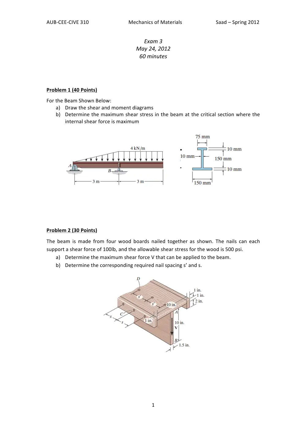
AUB-‐CEE-‐CIVE
310
Mechanics
of
Materials
Saad
–
Spring
2012
1
Exam
3
May
24,
2012
60
minutes
Problem
1
(40
Points)
For
the
Beam
Shown
Below:
a) Draw
the
shear
and
moment
diagrams
b) Determine
the
maximum
shear
stress
in
the
beam
at
the
critical
section
where
the
internal
shear
force
is
maximum
Problem
2
(30
Points)
The
beam
is
made
from
four
wood
boards
nailed
together
as
shown.
The
nails
can
each
support
a
shear
force
of
100lb,
and
the
allowable
shear
stress
for
the
wood
is
500
psi.
a) Determine
the
maximum
shear
force
V
that
can
be
applied
to
the
beam.
b) Determine
the
corresponding
required
nail
spacing
s’
and
s.
AUB-‐CEE-‐CIVE
310
Mechanics
of
Materials
Saad
–
Spring
2012
2
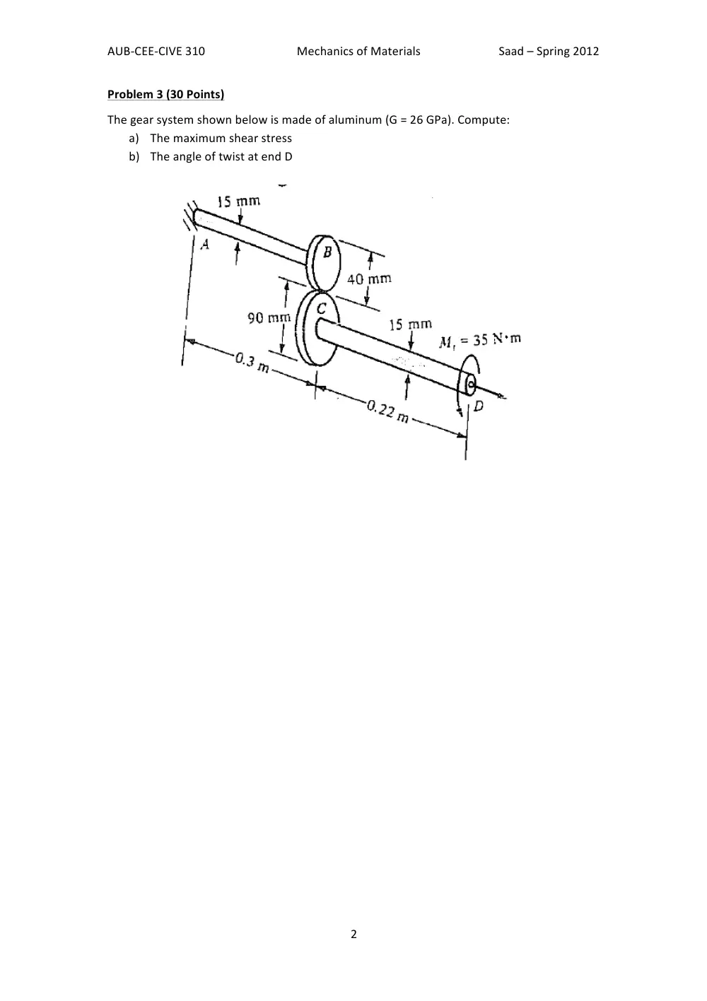
Problem
3
(30
Points)
The
gear
system
shown
below
is
made
of
aluminum
(G
=
26
GPa).
Compute:
a) The
maximum
shear
stress
b) The
angle
of
twist
at
end
D
AUB-CEE-CIVE 310 Mechanics of Materials
Saad – Spring 2012-13
1
Exam 3
May 7, 2013
60 minutes
Problem 1 (40 Points)
Problem 2 (30 Points)
Problem 3 (30 Points)
Three forces are applied to a 4-in. diameter plate
that is attached to the solid 1.8-in. diameter shaft
AB. Determine the normal and shearing stresses at
point H.
For the state of stress shown:
(a) Compute the normal and shear stress for the
shaded region using equilibrium by summing
forces.
(b) Represent this state of stress in terms of the
principal stresses and the maximum in plane
shear stresses.
A steel shaft and an aluminum tube are connected to a
fixed support and to a rigid disk as shown in the cross-
section below. Knowing that the initial stresses are
zero, determine the maximum torque that can be
applied to the disk if the allowable stresses are
120MPa in the steel shaft and 70MPa in the aluminum
tube. Use G = 77GPa for steel and G = 27GPa for
aluminum.