
EECE 200 Project Proposal, Fall 2011
American University of Beirut · Introduction to Electrical and Computer Engineering · 21 pages




Showing the first 10 of 21 pages. Download the PDF to see all of it.
More EECE 200 files
- Lecture Project Managment · Fall 2013ProjectView
- Project Proposal · Fall 2011ProjectView
- Project Proposal · Fall 2010ProjectView
- Report Design Project · Fall 2010ProjectView
- Project Proposal · Fall 2009ProjectView
- Project · Spring 2008ProjectView
- Project · Spring 2008ProjectView
- Homework 2 · Fall 2014HomeworkView
Show the text of this project
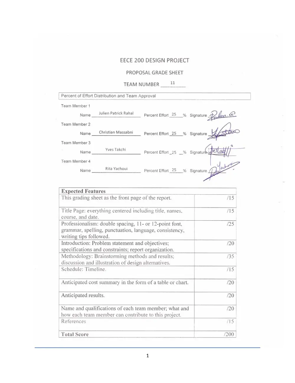
1
Project Proposal
ELEVATOR MODEL
Team number: 11
The group members are:
Yves Takchi 201200948
Christian Massabni 201200642
Rita Yachoui 201203800
Julien Rahal 201203217
2
Introduction
Project Purpose:
This project contributes to a big part of our final grades in EECE 200.
Therefore, for us to pass this course, it is necessary to complete this project.
Problem Statement:
In this project, we are going to build and program a 3-floor model elevator.
The programming and control interface will be developed using National
Instruments Labview software. The program will be downloaded to a NI
Speedy 33 DSP board that will run on standalone mode.
Project Objectives
While building a LABview VI designed to operate an elevator we will :
1. Enhance our LABview programming skills and apply them to a practical
application.
2. Understand the problem solving process.
3. Learn how to design and develop an engineering projects
3
4. Develop our ability to work in a team of engineers
Project Specifications
:
1. Digital Inputs :
Three photo resistors fixed on each floor, to receive light from a light
bulb fixed below the elevator cabin.
Three digital switches on each of the floors to allow the user to call the
elevator
A fourth photo resistor inside the cabin near the door entrance that is
constantly hit by an infrared or laser light. If something obstructs the
light, the sensor indicates it.
A digital input for a temperature sensor installed to the cabin
2. Analog input
The built in microphones on the speedy 33 board. Three
specific tones are assigned to each level which will allow
the program to determine what itinerary to take.
3. Digital Output :
Two digital outputs to a seven segment display on the
first floor used to display the position of the elevator
4
Three digital outputs that control the motors that
opens/closes the doors of each floors.
One digital output controlling the pulling motor's
direction.
One digital output that controls a dc fan installed in the
elevator.
Project constraints :
The use of the speedy 33 board is mandatory.
LAB view graphical programming language is required.
The group team members are limited to 4.
The project is subject to a time limit.
5
Organization
Page
o
Grading Sheet
1
o
Title Page
2
6
o
Introduction:
3
Project Purpose
3
Problem Statement
3
Project Objectives
3
Project Specification
4
Project Constraints
5
o
Methodology:
Brainstorming methods and results
7-8-9
Design alternatives:
first design with illustration 10-
11-12
first alternative
13
7
second alternative
13
efficiency discussion 13-
14
o
Time schedule
14
o
Cost estimation
15
o
Anticipated results
16
o
Team member qualifications
17
o
References
18
Methodology:
o
Brainstorming Methods and Results:
8
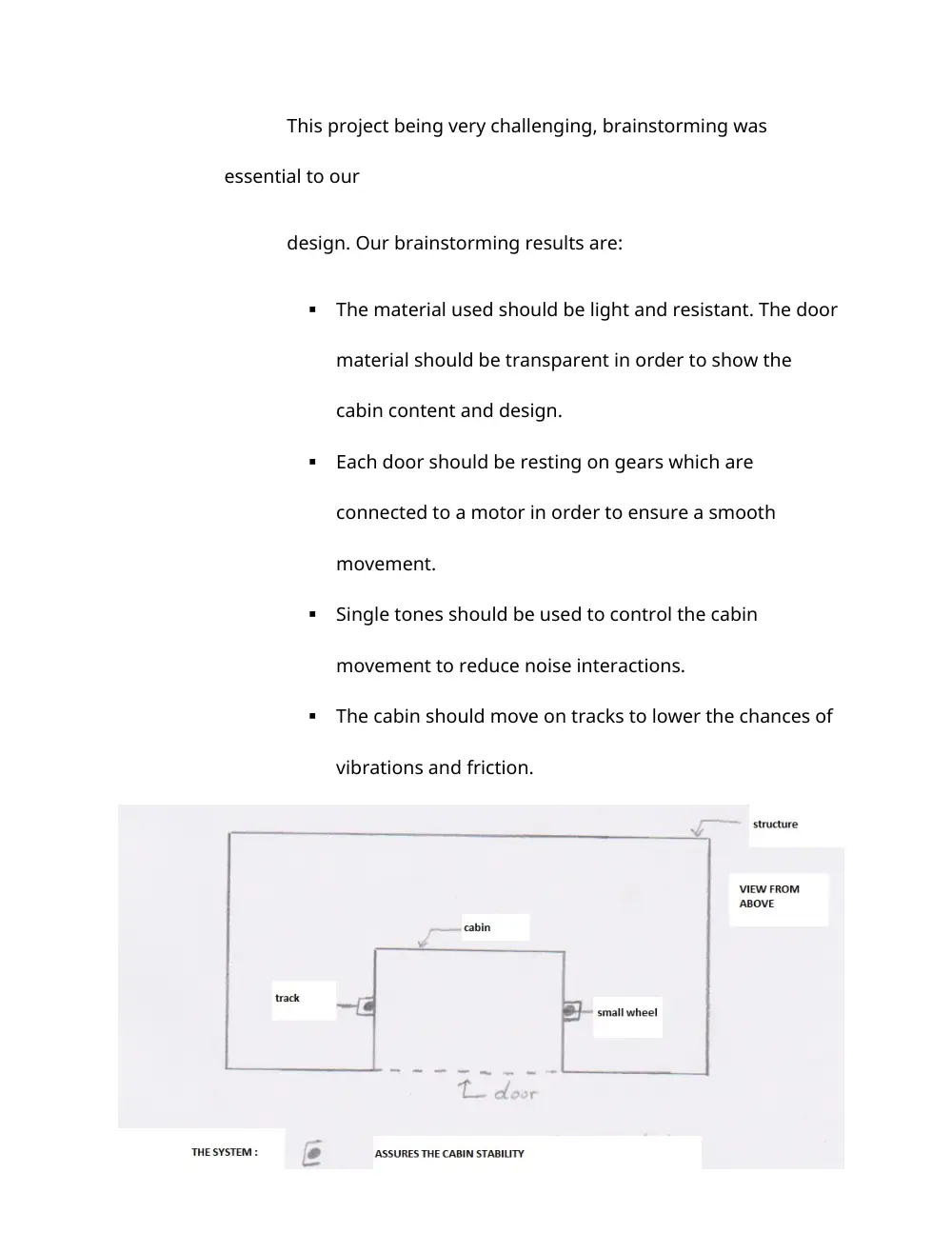
This project being very challenging, brainstorming was
essential to our
design. Our brainstorming results are:
The material used should be light and resistant. The door
material should be transparent in order to show the
cabin content and design.
Each door should be resting on gears which are
connected to a motor in order to ensure a smooth
movement.
Single tones should be used to control the cabin
movement to reduce noise interactions.
The cabin should move on tracks to lower the chances of
vibrations and friction.
9
The level sensors should be continuous and not discrete
(this will be explained in the efficiency discussion).
The pulling motor should be placed on the highest part
of the shaft and pull a counter weight.
The single seven segment display should be placed on
the first floor.
The door obstruction sensor should be placed inside the
cabin in order to minimize sensor quantity.
A door should be placed on every floor.
10
A temperature sensor records the temperature. If the
temperature exceeds a certain threshold, the cabin goes
into a safe mode. The lighting changes and a dc fan are
activated.
The speedy should work on stand-alone mode.
11
All wirings should be hidden inside the shaft.
o
First design:
The material for the shaft and skeleton and cabin is
aluminum composite material (aluminum-PVC) and the
doors are made out of Plexiglas.
Level sensors: Three photo resistors are installed on each
floor on the inside of the shaft, and one large radius light
bulb is fixed below the elevator cabin. When the cabin
reaches a level, the light from the light bulb hits the
photo resistor and the sensor circuit is closed, indicating
the presence of the cabin on that floor. When no light
hits the sensor the circuit is opened.
12
Door sensors: a single photo resistor is placed in the
inside threshold of the cabin with an infrared source
constantly hitting it. When something obstructs the
infrared beam, no light hits the photo resistor and the
circuit is open, preventing the door from closing.
A motor with gears attached to the door on each level , a
command opens half of it with one rotational
motion( clockwise) and closes with a second command
that turns it in the opposite rotational motion ( counter
clockwise).
13
A motor on the top of the shaft pulls and drops a
counterweight connected to the cabin. When the motor
isn’t running, the weight of the counterweight prevents
the cabin from sliding.
14
A temperature sensor inside the cabin gives real time
data collection to the speedy board. If the temperature
exceeds the threshold, a dc fan on the top of the cabin is
activated and the lighting changes to a single red LED.
Push buttons are fixed on every level to allow the user to
call the elevator from a floor
o
First Alternative
15
Level Sensors : 3 motion detectors fixed on every level
detect the passing of the elevator
Door sensor : a laser emitting diode hits the photo
resistor instead of the infrared emitter
Switches are used instead of the push buttons to call the
elevator
o
Second Alternative
Level Sensors: A metal plate is placed underneath the
cabin with a piece sticking out, and on each floor an open
circuit that close when the metal piece of the elevator
comes in contact with it, indicating the presence of the
elevator on that floor.
Door sensor: a motion detector detects if someone is
moving near the door entrance.
o
Efficiency discussion:
Level sensors: the light bulb/photo resistor solution
seems the most efficient .The motion sensor solution
offers an easy fix but the collected data is discrete , it
only shows that the elevator has passed a point ,when it
is idle it cannot determine the cabin’s position. The metal
16
plate solution offers too many failing scenarios (the plate
doesn’t hit the circuit as it should, the plate gets
damaged…)
Door sensors: the motion sensor is easy to procure but
again offers only discrete data collection. Between the
infrared/laser solutions, the infrared is more efficient but
the laser emitter is easier to procure.
Switches: both solutions are equally efficient but push
buttons are more harmonious with the elevator design.
Time Schedule :
Dates & Deadlines
Work due or done
Wednesday 16th Nov 2011
Group Formation (Naming) & Planning
For Meetings
Saturday 19th Nov 2011
Brain Storming & Research
Friday 25th Nov 2011
Exchange Of Ideas & Work On Proposal
Monday 28th Nov 2011
Proposal Report
Friday 16th Dec 2011
Project Soft Demonstration
Wednesday 11th Jan 2012
Project Deadline Software And Hardware
Thursday 12th & Friday 13th Jan 2012
Project Presentation And Demo
Friday 28th Jan 2012
Project Final Report & Log Book
17
*Extra meetings after the 28th of November will be scheduled later.
Anticipated Cost Summary:
Anticipated Results:
18
As a final result, we expect the elevator to function properly and according to plan. Our
elevator should go up and down three floors without any unnecessary vibrations and
while supplying full safety for its passengers. The elevator will respond to the calls on
the different floors and will attend the different calls from the floors in the order or
sequence that will be saved. The elevator will stop at every floor for 7 seconds if the
cabin is clear. The elevator doors will not open except when the elevator reaches the
specific floor. The motors and their direction should be arranged in a way to prevent the
stopping of elevator cabin between the floors; the elevator should only stop when
reaching the specific floors. The dc fan will be working according to the temperature
sensor. As we will show during the project presentation, the hair dryer that initializes
the change in temperature will be identified by the temperature sensor. Therefore the
dc fan will be turned on or off according to the indication of the temperature sensor
where the dc fan will be activated whenever the temperature exceeds some threshold
temperature (which will be in degrees Celsius). Additional features will be included like
the lightning, braking system and other audio effects. As for the sensors, their function
is to stop the closing of the door when someone enters the elevator.
Qualifications:
19
Each member of our group has participated effectively in this project. Each of us had a
different function depending on his or her own skills and knowledge. The work on the
project was divided in the following way according to each member:
Name
Qualifications
Allocated part of the project
Julien Rahal
Great organizational and
cooperative skills. Clear
understanding of the
procedure and project
material. Also has a skill in
illustrating and drawing
sketches.
Assures the complete
interaction between the group
members. Drew the designs
clearly after they have been
presented as essential ideas.
Yves Takchi
Deep understanding of the
material and know-how of the
project realization procedure,
and mastery of the English
writing language.
Presenting the basic ideas
about the project and
knowledge about where to
find each material needed. Did
the initial. Participated in
editing the final draft of the
proposal.
Christian Massabni
Very good leadership and
organizational skills. Time
management skills. Basic
understanding of all the
information presented during
group discussions.
Organization of the group
work and control over all the
work done. Time management
for the group. Participated in
editing the final draft of the
proposal.
Rita Yachoui
Good mastery of the English
Language. Responsible for
typing the proposal report.
Offering creative ideas and
additional aspects and
components for the project.
Doing research on the subject.
Participation in the group
discussions as well as offering
ideas.
The four members have attended every group meeting and there was full cooperation and
agreement.
References:
20
Boujikian Electronics, Dora, Beirut-Tripoli Highway.
Proximity, Kaslik, Espace 2000 Building, ground floor.
21