
EECE 210C Lecture, Fall 2002
American University of Beirut · Electric Circuits for Civil Engineers · 18 pages
Showing the first 10 of 18 pages. Download the PDF to see all of it.
More EECE 210C files
Show the text of this lab
2
Circuit Elements
Assessment Problems
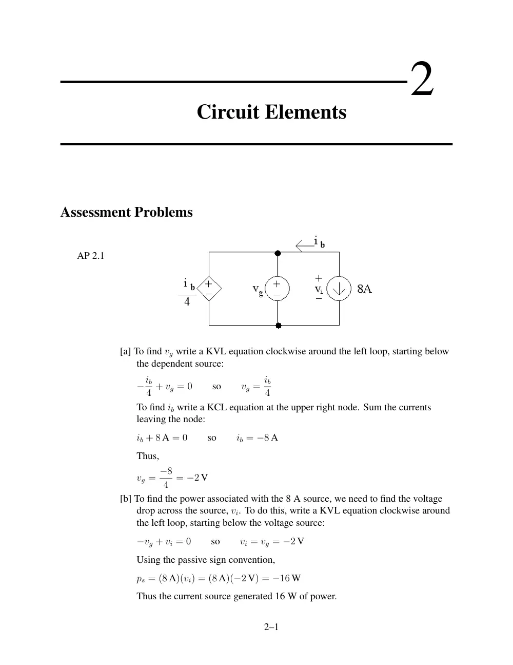
AP 2.1
[a] To find vg write a KVL equation clockwise around the left loop, starting below
the dependent source:
−ib
4 + vg = 0
so
vg = ib
4
To find ib write a KCL equation at the upper right node. Sum the currents
leaving the node:
ib + 8 A = 0
so
ib = −8 A
Thus,
vg = −8
4 = −2 V
[b] To find the power associated with the 8 A source, we need to find the voltage
drop across the source, vi. To do this, write a KVL equation clockwise around
the left loop, starting below the voltage source:
−vg + vi = 0
so
vi = vg = −2 V
Using the passive sign convention,
ps = (8 A)(vi) = (8 A)(−2 V) = −16 W
Thus the current source generated 16 W of power.
2–1
2–2
CHAPTER 2. Circuit Elements
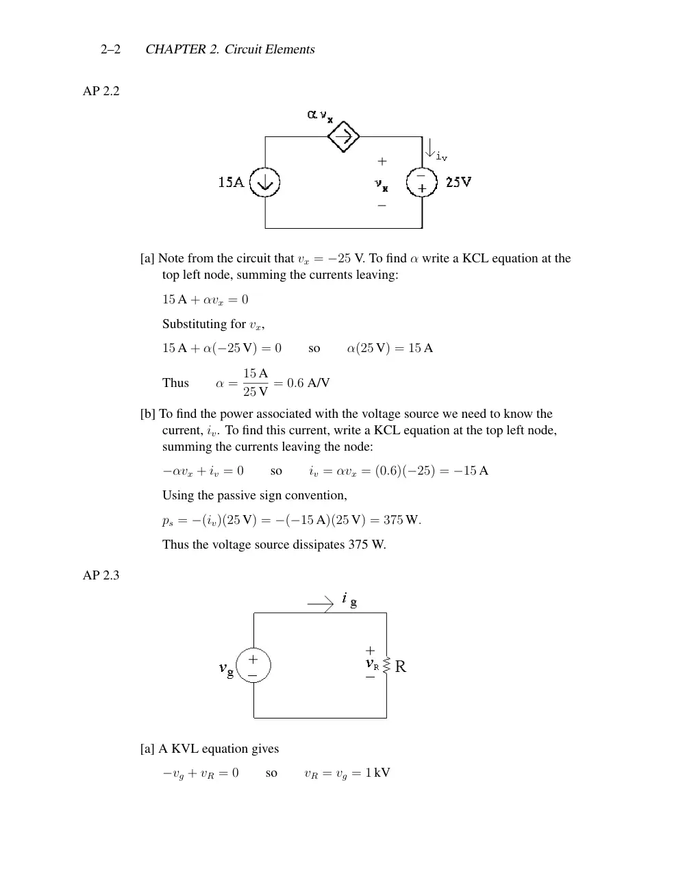
AP 2.2
[a] Note from the circuit that vx = −25 V. To find α write a KCL equation at the
top left node, summing the currents leaving:
15 A + αvx = 0
Substituting for vx,
15 A + α(−25 V) = 0
so
α(25 V) = 15 A
Thus
α = 15 A
25 V = 0.6 A/V
[b] To find the power associated with the voltage source we need to know the
current, iv. To find this current, write a KCL equation at the top left node,
summing the currents leaving the node:
−αvx + iv = 0
so
iv = αvx = (0.6)(−25) = −15 A
Using the passive sign convention,
ps = −(iv)(25 V) = −(−15 A)(25 V) = 375 W.
Thus the voltage source dissipates 375 W.
AP 2.3
[a] A KVL equation gives
−vg + vR = 0
so
vR = vg = 1 kV
Problems
2–3
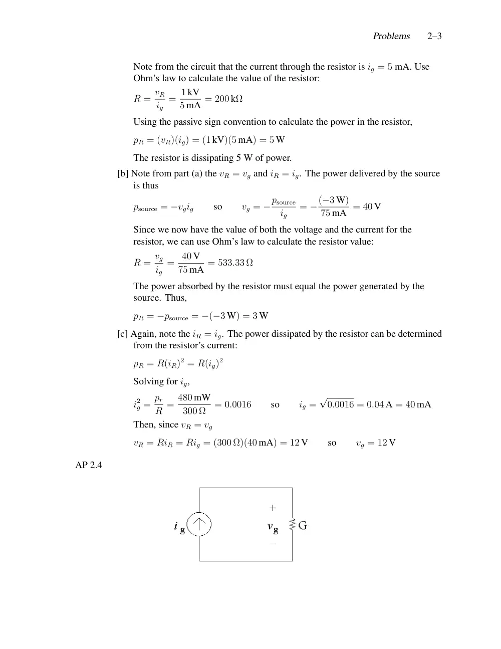
Note from the circuit that the current through the resistor is ig = 5 mA. Use
Ohm’s law to calculate the value of the resistor:
R = vR
ig
= 1 kV
5 mA = 200 kΩ
Using the passive sign convention to calculate the power in the resistor,
pR = (vR)(ig) = (1 kV)(5 mA) = 5 W
The resistor is dissipating 5 W of power.
[b] Note from part (a) the vR = vg and iR = ig. The power delivered by the source
is thus
psource = −vgig
so
vg = −psource
ig
= −(−3 W)
75 mA = 40 V
Since we now have the value of both the voltage and the current for the
resistor, we can use Ohm’s law to calculate the resistor value:
R = vg
ig
= 40 V
75 mA = 533.33 Ω
The power absorbed by the resistor must equal the power generated by the
source. Thus,
pR = −psource = −(−3 W) = 3 W
[c] Again, note the iR = ig. The power dissipated by the resistor can be determined
from the resistor’s current:
pR = R(iR)2 = R(ig)2
Solving for ig,
i2
g = pr
R = 480 mW
300 Ω
= 0.0016
so
ig =
√
0.0016 = 0.04 A = 40 mA
Then, since vR = vg
vR = RiR = Rig = (300 Ω)(40 mA) = 12 V
so
vg = 12 V
AP 2.4
2–4
CHAPTER 2. Circuit Elements
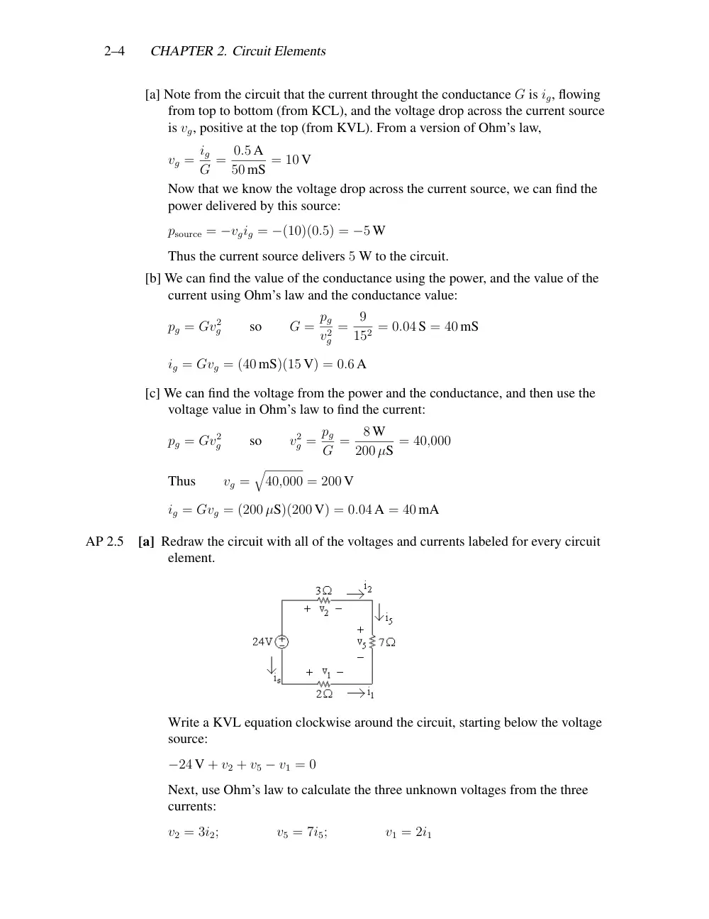
[a] Note from the circuit that the current throught the conductance G is ig, flowing
from top to bottom (from KCL), and the voltage drop across the current source
is vg, positive at the top (from KVL). From a version of Ohm’s law,
vg = ig
G = 0.5 A
50 mS = 10 V
Now that we know the voltage drop across the current source, we can find the
power delivered by this source:
psource = −vgig = −(10)(0.5) = −5 W
Thus the current source delivers 5 W to the circuit.
[b] We can find the value of the conductance using the power, and the value of the
current using Ohm’s law and the conductance value:
pg = Gv2
g
so
G = pg
v2
g
=
9
152 = 0.04 S = 40 mS
ig = Gvg = (40 mS)(15 V) = 0.6 A
[c] We can find the voltage from the power and the conductance, and then use the
voltage value in Ohm’s law to find the current:
pg = Gv2
g
so
v2
g = pg
G =
8 W
200 µS = 40,000
Thus
vg =
�
40,000 = 200 V
ig = Gvg = (200 µS)(200 V) = 0.04 A = 40 mA
AP 2.5
[a] Redraw the circuit with all of the voltages and currents labeled for every circuit
element.
Write a KVL equation clockwise around the circuit, starting below the voltage
source:
−24 V + v2 + v5 − v1 = 0
Next, use Ohm’s law to calculate the three unknown voltages from the three
currents:
v2 = 3i2;
v5 = 7i5;
v1 = 2i1
Problems
2–5
A KCL equation at the upper right node gives i2 = i5; a KCL equation at the
bottom right node gives i5 = −i1; a KCL equation at the upper left node gives
is = −i2. Now replace the currents i1 and i2 in the Ohm’s law equations with
i5:
v2 = 3i2 = 3i5;
v5 = 7i5;
v1 = 2i1 = −2i5
Now substitute these expressions for the three voltages into the first equation:
24 = v2 + v5 − v1 = 3i5 + 7i5 − (−2i5) = 12i5
Therefore i5 = 24/12 = 2 A
[b] v1 = −2i5 = −2(2) = −4 V
[c] v2 = 3i5 = 3(2) = 6 V
[d] v5 = 7i5 = 7(2) = 14 V
[e] A KCL equation at the lower left node gives is = i1. Since i1 = −i5, is = −2 A.
We can now compute the power associated with the voltage source:
p24 = (24)is = (24)(−2) = −48 W
Therefore 24 V source is delivering 48 W.
AP 2.6
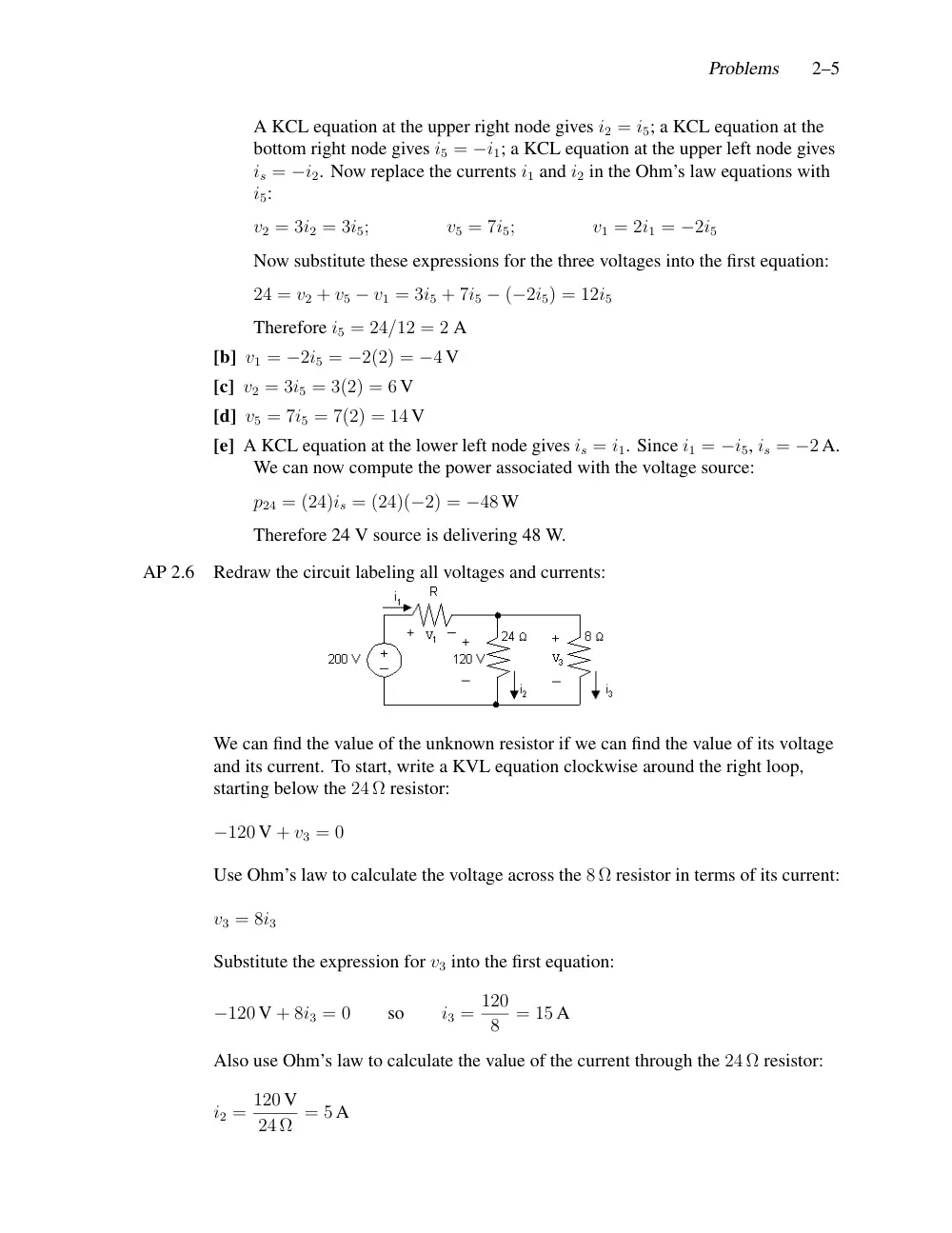
Redraw the circuit labeling all voltages and currents:
We can find the value of the unknown resistor if we can find the value of its voltage
and its current. To start, write a KVL equation clockwise around the right loop,
starting below the 24 Ω resistor:
−120 V + v3 = 0
Use Ohm’s law to calculate the voltage across the 8 Ω resistor in terms of its current:
v3 = 8i3
Substitute the expression for v3 into the first equation:
−120 V + 8i3 = 0
so
i3 = 120
8
= 15 A
Also use Ohm’s law to calculate the value of the current through the 24 Ω resistor:
i2 = 120 V
24 Ω = 5 A
2–6
CHAPTER 2. Circuit Elements
Now write a KCL equation at the top middle node, summing the currents leaving:
−i1 + i2 + i3 = 0
so
i1 = i2 + i3 = 5 + 15 = 20 A
Write a KVL equation clockwise around the left loop, starting below the voltage
source:
−200 V + v1 + 120 V = 0
so
v1 = 200 − 120 = 80 V
Now that we know the values of both the voltage and the current for the unknown
resistor, we can use Ohm’s law to calculate the resistance:
R = v1
i1
= 80
20 = 4 Ω
AP 2.7
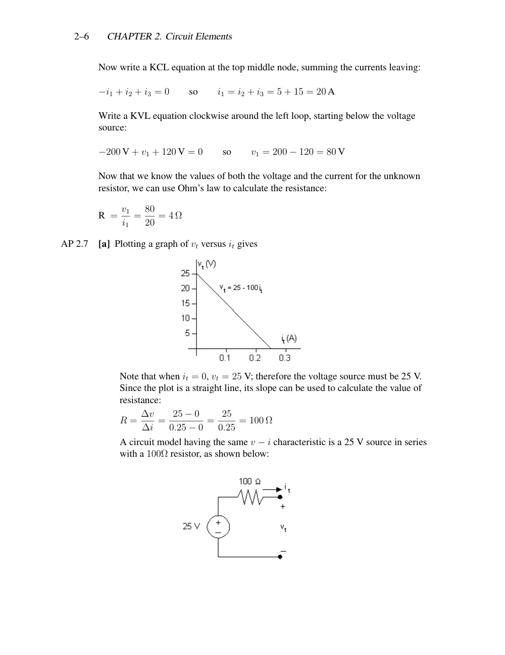
[a] Plotting a graph of vt versus it gives
Note that when it = 0, vt = 25 V; therefore the voltage source must be 25 V.
Since the plot is a straight line, its slope can be used to calculate the value of
resistance:
R = ∆v
∆i = 25 − 0
0.25 − 0 = 25
0.25 = 100 Ω
A circuit model having the same v − i characteristic is a 25 V source in series
with a 100Ω resistor, as shown below:
Problems
2–7
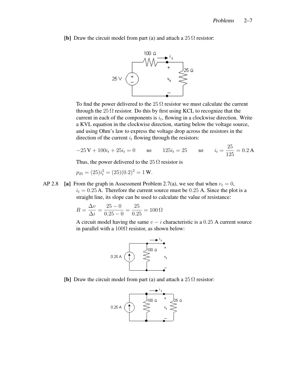
[b] Draw the circuit model from part (a) and attach a 25 Ω resistor:
To find the power delivered to the 25 Ω resistor we must calculate the current
through the 25 Ω resistor. Do this by first using KCL to recognize that the
current in each of the components is it, flowing in a clockwise direction. Write
a KVL equation in the clockwise direction, starting below the voltage source,
and using Ohm’s law to express the voltage drop across the resistors in the
direction of the current it flowing through the resistors:
−25 V + 100it + 25it = 0
so
125it = 25
so
it = 25
125 = 0.2 A
Thus, the power delivered to the 25 Ω resistor is
p25 = (25)i2
t = (25)(0.2)2 = 1 W.
AP 2.8
[a] From the graph in Assessment Problem 2.7(a), we see that when vt = 0,
it = 0.25 A. Therefore the current source must be 0.25 A. Since the plot is a
straight line, its slope can be used to calculate the value of resistance:
R = ∆v
∆i = 25 − 0
0.25 − 0 = 25
0.25 = 100 Ω
A circuit model having the same v − i characteristic is a 0.25 A current source
in parallel with a 100Ω resistor, as shown below:
[b] Draw the circuit model from part (a) and attach a 25 Ω resistor:
2–8
CHAPTER 2. Circuit Elements
Note that by writing a KVL equation around the right loop we see that the
voltage drop across both resistors is vt. Write a KCL equation at the top center
node, summing the currents leaving the node. Use Ohm’s law to specify the
currents through the resistors in terms of the voltage drop across the resistors
and the value of the resistors.
−0.25 + vt
100 + vt
25 = 0,
so
5vt = 25,
thus
vt = 5 V
p25 = v2
t
25 = 1 W.
AP 2.9
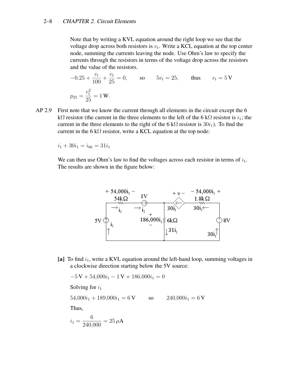
First note that we know the current through all elements in the circuit except the 6
kΩ resistor (the current in the three elements to the left of the 6 kΩ resistor is i1; the
current in the three elements to the right of the 6 kΩ resistor is 30i1). To find the
current in the 6 kΩ resistor, write a KCL equation at the top node:
i1 + 30i1 = i6k = 31i1
We can then use Ohm’s law to find the voltages across each resistor in terms of i1.
The results are shown in the figure below:
[a] To find i1, write a KVL equation around the left-hand loop, summing voltages in
a clockwise direction starting below the 5V source:
−5 V + 54,000i1 − 1 V + 186,000i1 = 0
Solving for i1
54,000i1 + 189,000i1 = 6 V
so
240,000i1 = 6 V
Thus,
i1 =
6
240,000 = 25 µA
Problems
2–9
[b] Now that we have the value of i1, we can calculate the voltage for each
component except the dependent source. Then we can write a KVL equation
for the right-hand loop to find the voltage v of the dependent source. Sum the
voltages in the clockwise direction, starting to the left of the dependent source:
+v − 54,000i1 + 8 V − 186,000i1 = 0
Thus,
v = 240,000i1 − 8 V = 240,000(25 × 10−6) − 8 V = 6 V − 8 V = −2 V
We now know the values of voltage and current for every circuit element. Let’s
construct a power table:
Element
Current
Voltage
Power
Power
(µA)
(V)
Equation
(µW)
5 V
25
5
p = −vi
−125
54 kΩ
25
1.35
p = Ri2
33.75
1 V
25
1
p = −vi
−25
6 kΩ
775
4.65
p = Ri2
3603.75
Dep. source
750
−2
p = −vi
1500
1.8 kΩ
750
1.35
p = Ri2
1012.5
8 V
750
8
p = −vi
−6000
[c] The total power generated in the circuit is the sum of the negative power values
in the power table:
−125 µW + −25 µW + −6000 µW = −6150 µW
Thus, the total power generated in the circuit is 6150 µW.
[d] The total power absorbed in the circuit is the sum of the positive power values in
the power table:
33.75 µW + 3603.75 µW + 1500 µW + 1012.5 µW = 6150 µW
Thus, the total power absorbed in the circuit is 6150 µW.
AP 2.10 Given that iφ = 2 A, we know the current in the dependent source is 2iφ = 4 A. We
can write a KCL equation at the left node to find the current in the 10 Ω resistor.
Summing the currents leaving the node,
−5 A + 2 A + 4 A + i10Ω = 0
so
i10Ω = 5 A − 2 A − 4 A = −1 A
2–10
CHAPTER 2. Circuit Elements
Thus, the current in the 10 Ω resistor is 1 A, flowing right to left, as seen in the
circuit below.
[a] To find vs, write a KVL equation, summing the voltages counter-clockwise
around the lower right loop. Start below the voltage source.
−vs + (1 A)(10 Ω) + (2 A)(30 Ω) = 0
so
vs = 10 V + 60 V = 70 V
[b] The current in the voltage source can be found by writing a KCL equation at the
right-hand node. Sum the currents leaving the node
−4 A + 1 A + iv = 0
so
iv = 4 A − 1 A = 3 A
The current in the voltage source is 3 A, flowing top to bottom. The power
associated with this source is
p = vi = (70 V)(3 A) = 210 W
Thus, 210 W are absorbed by the voltage source.
[c] The voltage drop across the independent current source can be found by writing
a KVL equation around the left loop in a clockwise direction:
−v5A + (2 A)(30 Ω) = 0
so
v5A = 60 V
The power associated with this source is
p = −v5Ai = −(60 V)(5 A) = −300 W
This source thus delivers 300 W of power to the circuit.
[d] The voltage across the controlled current source can be found by writing a KVL
equation around the upper right loop in a clockwise direction:
+v4A + (10 Ω)(1 A) = 0
so
v4A = −10 V
The power associated with this source is
p = v4Ai = (−10 V)(4 A) = −40 W
This source thus delivers 40 W of power to the circuit.
[e] The total power dissipated by the resistors is given by
(i30Ω)2(30 Ω) + (i10Ω)2(10 Ω) = (2)2(30 Ω) + (1)2(10 Ω) = 120 + 10 = 130 W
Problems
2–11
Problems
P 2.14
[a] Write a KVL equation clockwise aroud the right loop, starting below the 300 Ω
resistor:
−va + vb = −0
so
va = vb
Using Ohm’s law,
va = 300ia
and
vb = 75ib
Substituting,
300ia = 75ib
so
ib = 4ia
Write a KCL equation at the top middle node, summing the currents leaving:
−ig + ia + ib = 0
so
ig = ia + ib = ia + 4ia = 5ia
Write a KVL equation clockwise around the left loop, starting below the
voltage source:
−200 V + v40 + va = 0
From Ohm’s law,
v40 = 40ig
and
va = 300ia
Substituting,
−200 V + 40ig + 300ia = 0
Subsituting for ig:
−200 V + 40(5ia) + 300ia = −200 V + 200ia + 300ia = −200 V + 500ia = 0
Thus,
500ia = 200 V
so
ia = 200 V
500
= 0.4 A
[b] From part (a), ib = 4ia = 4(0.4 A) = 1.6 A.
[c] From the circuit, vo = 75 Ω(ib) = 75 Ω(1.6 A) = 120 V.
2–12
CHAPTER 2. Circuit Elements
[d] Use the formula pR = Ri2
R to calculate the power absorbed by each resistor:
p40Ω = i2
g(40 Ω) = (5ia)2(40 Ω) = [5(0.4)]2(40 Ω) = (2)2(40 Ω) = 160 W
p300Ω = i2
a(300 Ω) = (0.4)2(300 Ω) = 48 W
p75Ω = i2
b(75 Ω) = (4ia)2(75 Ω) = [4(0.4)]2(75 Ω) = (1.6)2(75 Ω) = 192 W
[e] Using the passive sign convention,
psource = −(200 V)ig = −(200 V)(5ia) = −(200 V)[5(0.4 A)]
= −(200 V)(2 A) = −400 W
Thus the voltage source delivers 400 W of power to the circuit. Check:
�
Pdis = 160 + 48 + 192 = 400 W
�
Pdel = 400 W
P 2.16
[a] Write a KVL equation clockwise around the right loop:
−v60 + v30 + v90 = 0
From Ohm’s law,
v60 = (60 Ω)(4 A) = 240 V,
v30 = 30io,
v90 = 90io
Substituting,
−240 V + 30io + 90io = 0
so
120io = 240 V
Thus
io = 240 V
120
= 2 A
Now write a KCL equatiohn at the top middle node, summing the currents
leaving:
−ig + 4 A + io = 0
so
ig = 4 A + 2 A = 6 A
[b] Write a KVL equation clockwise around the left loop:
−vo + v60 = 0
so
vo = v60 = 240 V
Problems
2–13
[c] Calculate power using p = vi for the source and p = Ri2 for the resistors:
psource = −voig = −(240 V)(6 A) = −1440 W
p60Ω = 42(60) = 960 W
p30Ω = 30i2
o = (30)22 = 120 W
p90Ω = 90i2
o = (90)22 = 360 W
�
Pdev = 1440 W
�
Pabs = 960 + 120 + 360 = 1440 W
P 2.21
[a] Plot the v—i characteristic:
From the plot:
R = ∆v
∆i = 130 − (−30)
8 − 0
= 20 Ω
When it = 0, vt = −30 V; therefore the ideal voltage source has a voltage of
−30 V. Thus the device can be modeled as a −30 V source in series with a
20 Ω resistor, as shown below:
[b] We attach a 40 Ω resistor to the device model developed in part (a):
2–14
CHAPTER 2. Circuit Elements
Write a KVL equation clockwise around the circuit, using Ohm’s law to
express the voltage drop across the resistors in terms of the current it through
the resistors:
−(−30 V) − 20it − 40it = 0
so
− 60it = −30 V
Thus
it = −30 V
−60
= +0.5 A
Now calculate the power dissipated by the resistor:
p40 Ω = 40i2
t = (40)(0.5)2 = 10 W
P 2.23
[a] Begin by constructing a plot of voltage versus current:
[b] Since the plot is linear for 0 ≤ is ≤ 24 A amd since R = ∆v/∆i, we can
calculate R from the plotted values as follows:
R = ∆v
∆i = 24 − 18
24 − 0 = 6
24 = 0.25 Ω
We can determine the value of the ideal voltage source by considering the
value of vs when is = 0. When there is no current, there is no voltage drop
across the resistor, so all of the voltage drop at the output is due to the voltage
source. Thus the value of the voltage source must be 24 V. The model, valid
for 0 ≤ is ≤ 24 A, is shown below:
Problems
2–15
[c] The circuit is shown below:
Write a KVL equation in the clockwise direction, starting below the voltage
source. Use Ohm’s law to express the voltage drop across the resistors in terms
of the current i:
−24 V + 0.25i + 1i = 0
so
1.25i = 24 V
Thus,
i = 24 V
1.25 Ω = 19.2 A
[d] The circuit is shown below:
Write a KVL equation in the clockwise direction, starting below the voltage
source. Use Ohm’s law to express the voltage drop across the resistors in terms
of the current i:
−24 V + 0.25i = 0
so
0.25i = 24 V
Thus,
i = 24 V
0.25 Ω = 96 A
[e] The short circuit current can be found in the table of values (or from the plot) as
the value of the current is when the voltage vs = 0. Thus,
isc = 48 A
(from table)
[f] The plot of voltage versus current constructed in part (a) is not linear (it is
piecewise linear, but not linear for all values of is). Since the proposed circuit
model is a linear model, it cannot be used to predict the nonlinear behavior
exhibited by the plotted data.
P 2.26
[a] Start with the 22.5 Ω resistor. Since the voltage drop across this resistor is 90 V,
we can use Ohm’s law to calculate the current:
i22.5 Ω = 90 V
22.5 Ω = 4 A
Next we can calculate the voltage drop across the 15 Ω resistor by writing a
KVL equation around the outer loop of the circuit:
−240 V + 90 V + v15 Ω = 0
so
v15 Ω = 240 − 90 = 150 V
2–16
CHAPTER 2. Circuit Elements
Now that we know the voltage drop across the 15 Ω resistor, we can use Ohm’s
law to find the current in this resistor:
i15 Ω = 150 V
15 Ω = 10 A
Write a KCL equation at the middle right node to find the current through the
5 Ω resistor. Sum the currents entering:
4 A − 10 A + i5 Ω = 0
so
i5 Ω = 10 A − 4 A = 6 A
Write a KVL equation clockwise around the upper right loop, starting below
the 4 Ω resistor. Use Ohm’s law to express the voltage drop across the resistors
in terms of the current through the resistors:
−v4 Ω + 90 V + (5 Ω)(−6 A) = 0
so
v4 Ω = 90 V − 30 V = 60 V
Using Ohm’s law we can find the current through the 4 Ω resistor:
i4 Ω = 60 V
4 Ω = 15 A
Write a KCL equation at the middle node. Sum the currents entering:
15 A − 6 A − i20 Ω = 0
so
i20 Ω = 15 A − 6 A = 9 A
Use Ohm’s law to calculate the voltage drop across the 20 Ω resistor:
v20 Ω = (20 Ω)(9 A) = 180 V
All of the voltages and currents calculated above are shown in the figure below:
Calculate the power dissipated by the resistors using the equation pR = Ri2
R:
p4Ω = (4)(15)2 = 900 W
p20Ω = (20)(9)2 = 1620 W
p5Ω = (5)(6)2 = 180 W
p22.5Ω = (22.5)(4)2 = 360 W
p15Ω = (15)(10)2 = 1500 W
[b] We can calculate the current in the voltage source, ig by writing a KCL equation
at the top middle node:
ig = 15 A + 4 A = 19 A
Problems
2–17
Now that we have both the voltage and the current for the source, we can
calculate the power supplied by the source:
pg = −240(19) = −4560 W
thus
pg (supplied) = 4560 W
[c]
�
Pdis = 900 + 1620 + 180 + 360 + 1500 = 4560 W
Therefore,
�
Psupp =
�
Pdis
P 2.29
First note that we know the current through all elements in the circuit except the
200 Ω resistor (the current in the three elements to the left of the 200 Ω resistor is iβ;
the current in the three elements to the right of the 200 Ω resistor is 49iβ). To find
the current in the 200 Ω resistor, write a KCL equation at the top node:
iβ + 49iβ = i200 Ω = 50iβ
We can then use Ohm’s law to find the voltages across each resistor in terms of iβ.
The results are shown in the figure below:
[a] To find iβ, write a KVL equation around the left-hand loop, summing voltages
in a clockwise direction starting below the 7.2V source:
−7.2 V + 55,000i1 + 0.7 V + 10,000iβ = 0
Solving for iβ
55,000iβ + 10,000iβ = 6.5 V
so
65,000iβ = 6.5 V
Thus,
iβ =
6.5
65,000 = 100 µA
Now that we have the value of iβ, we can calculate the voltage for each
component except the dependent source. Then we can write a KVL equation
for the right-hand loop to find the voltage vy of the dependent source. Sum the
voltages in the clockwise direction, starting to the left of the dependent source:
−vy − 24,500iβ + 9 V − 10,000iβ = 0
Thus,
vy = 9 V − 34,500iβ = 9 V − 34,500(100 × 10−6) = 9 V − 3.45 V = 5.55 V
2–18
CHAPTER 2. Circuit Elements
[b] We now know the values of voltage and current for every circuit element. Let’s
construct a power table:
Element
Current
Voltage
Power
Power
(µA)
(V)
Equation
(µW)
7.2 V
100
7.2
p = −vi
−720
55 kΩ
100
5.5
p = Ri2
550
0.7 V
100
0.7
p = vi
70
200 Ω
5000
1
p = Ri2
5000
Dep. source
4900
5.55
p = vi
27,195
500 Ω
4900
2.45
p = Ri2
12,005
9 V
4900
9
p = −vi
−44,100
The total power generated in the circuit is the sum of the negative power values
in the power table:
−720 µW + −44,100 µW = −44,820 µW
Thus, the total power generated in the circuit is 44,820 µW. The total power
absorbed in the circuit is the sum of the positive power values in the power
table:
550 µW + 70 µW + 5000 µW + 27,195 µW + 12,005 µW = 44,820 µW
Thus, the total power absorbed in the circuit is 44,820 µW and the power in the
circuit balances.